EP1692474B1 - Tooth locating within dental images - Google Patents
Tooth locating within dental images Download PDFInfo
- Publication number
- EP1692474B1 EP1692474B1 EP04811913A EP04811913A EP1692474B1 EP 1692474 B1 EP1692474 B1 EP 1692474B1 EP 04811913 A EP04811913 A EP 04811913A EP 04811913 A EP04811913 A EP 04811913A EP 1692474 B1 EP1692474 B1 EP 1692474B1
- Authority
- EP
- European Patent Office
- Prior art keywords
- reference object
- dental
- tooth
- window
- active shape
- Prior art date
- Legal status (The legal status is an assumption and is not a legal conclusion. Google has not performed a legal analysis and makes no representation as to the accuracy of the status listed.)
- Expired - Lifetime
Links
Images
Classifications
-
- G—PHYSICS
- G01—MEASURING; TESTING
- G01J—MEASUREMENT OF INTENSITY, VELOCITY, SPECTRAL CONTENT, POLARISATION, PHASE OR PULSE CHARACTERISTICS OF INFRARED, VISIBLE OR ULTRAVIOLET LIGHT; COLORIMETRY; RADIATION PYROMETRY
- G01J3/00—Spectrometry; Spectrophotometry; Monochromators; Measuring colours
- G01J3/46—Measurement of colour; Colour measuring devices, e.g. colorimeters
- G01J3/50—Measurement of colour; Colour measuring devices, e.g. colorimeters using electric radiation detectors
- G01J3/508—Measurement of colour; Colour measuring devices, e.g. colorimeters using electric radiation detectors measuring the colour of teeth
-
- G—PHYSICS
- G06—COMPUTING OR CALCULATING; COUNTING
- G06T—IMAGE DATA PROCESSING OR GENERATION, IN GENERAL
- G06T7/00—Image analysis
- G06T7/10—Segmentation; Edge detection
- G06T7/12—Edge-based segmentation
-
- G—PHYSICS
- G06—COMPUTING OR CALCULATING; COUNTING
- G06T—IMAGE DATA PROCESSING OR GENERATION, IN GENERAL
- G06T7/00—Image analysis
- G06T7/10—Segmentation; Edge detection
- G06T7/149—Segmentation; Edge detection involving deformable models, e.g. active contour models
-
- G—PHYSICS
- G06—COMPUTING OR CALCULATING; COUNTING
- G06T—IMAGE DATA PROCESSING OR GENERATION, IN GENERAL
- G06T2207/00—Indexing scheme for image analysis or image enhancement
- G06T2207/20—Special algorithmic details
- G06T2207/20112—Image segmentation details
- G06T2207/20124—Active shape model [ASM]
-
- G—PHYSICS
- G06—COMPUTING OR CALCULATING; COUNTING
- G06T—IMAGE DATA PROCESSING OR GENERATION, IN GENERAL
- G06T2207/00—Indexing scheme for image analysis or image enhancement
- G06T2207/30—Subject of image; Context of image processing
- G06T2207/30004—Biomedical image processing
- G06T2207/30036—Dental; Teeth
Definitions
- the invention relates to digital image processing of dental images and more particularly relates to tooth locating within dental images.
- Modem dental procedures often involve the fabrication of restorations such as crowns, implants, fixed partial dentures, and veneers. Ceramics are often used in such restorations because their optical properties are such that skillfully produced ceramic restorations can closely match the shape, texture, color and translucency of natural teeth.
- Tooth color, texture, and translucency vary not only from patient to patient, but also from tooth to tooth in an individual patient and within a single tooth. Teeth vary in shape over a wide range. Information regarding the color and other appearance characteristics of a patient's teeth needs to be accurately determined and unambiguously conveyed to those who will be fabricating the restoration. While molds and other techniques can be used to record and transfer information regarding tooth shape and other geometric characteristics, techniques for determining and conveying color and other appearance characteristics are more problematic.
- shade matching involves visually matching a patient's tooth to one of a number of reference shade samples (shade tabs) within one or more sets of standardized shade guides.
- the person performing the match often a dentist, records the identification of the matching shade tab and conveys that information to the dental laboratory where the restoration will be fabricated.
- the laboratory then uses its own set of the same shade guides to perform visual color evaluations of the restoration throughout the fabrication process.
- the visual shade matching process has a number of problems: The initial matching procedure is often long, difficult, and tedious. It is not unusual for the process to take twenty minutes or longer. In most cases, there will be no shade tab that perfectly matches the patient's teeth. Deciding which tab matches most closely (i.e., which mismatches the least) is often problematic. Visual color evaluation of relatively small color differences is always difficult, and the conditions under which dental color evaluations are made are likely to give rise to a number of complicating psychophysical effects such as local chromatic adaptation, local brightness adaptation, and lateral-brightness adaptation. Frequently, the dentist will determine that the patient's teeth are particularly difficult to match. The patient then must go in person to the orthodontics laboratory that will be fabricating the restoration. There, trained laboratory personnel can perform the color match. In many cases, the patient will have to return to the dentist and laboratory two, three, or even more times as the color of the prosthesis is fine tuned by sequential additions of ceramics or other colored materials.
- WO 03/083765 discloses a method for locating a dental target within a digital dental image which applies a correction to the segmented tooth image without using a reference object.
- U.S. Patent Nos. 6,190,170 and 6,328,567, to Morris et al. describe a system that uses two or more references to normalize RGB image values from one or more digital cameras.
- U.S. Patent No. 6,384,917, to Fradkin describes a system that uses beam splitters and other optical components to obtain RGB image values. Once again, teeth and shade tabs are compared according to their RGB values or to HSI or other values derived from RGB values using a single set of conversion equations.
- U.S. Patent Application Publication No. US2002/0021439A1 to Priestley et al., also describes a color matching system in which colors are analyzed in terms of RGB values.
- the cross-referenced U.S. Patent Application by Giorgianni and Forsythe uses multiple subject-specific colorimetric transformations in a dental shade-matching system.
- Each colorimetric transformation is based on one specific subset of colors (e.g., natural teeth, shade tabs, prosthetic ceramics, etc.).
- colorimetric calibration is provided for each individual camera, each individual set of shade tabs, and each individual intra-oral reference.
- the system uses a two separate lighting arrangements to minimize or eliminates specular reflections within the area of measurement, and produce images that accurately convey supplemental information such as tooth texture, gloss, and other details.
- An intra-oral reference is used that has optical properties designed to be well correlated with those of natural teeth.
- a shade tab database is built using images of shade tabs photographed with artificial gums and with a background that simulates the human mouth.
- a standardized set of shade-tab colorimetric values and a corresponding set of computer-generated shade tab images are provided, which can serve as a standard for determining and communicating color specifications.
- Decision algorithms automatically determine the closest shade-tab match to one or more areas of a specified tooth. The degree of match is indicated in terms of a numerical values, and/or graphical representations, and/or corresponding verbal descriptions. Matching is based on comparisons of regions of interest that are selectable in number and location. Shape and color recognition algorithms simplify and/or fully automate the user task of locating and sizing regions of interest.
- the matching is also determined for any number of other shade tabs in the database, and the results are listed in rank order.
- the decision algorithm of the system includes parameters that can be adjusted to correspond with various shade-tab selection preferences and objectives. Multiple sets of parameters values, each corresponding to the preferences of a particular user or situation, can be stored and selected for use. An on-screen visual comparison pairs the measured tooth and a selected shade tab.
- the system provides for visualization of a proposed prosthesis within an image of the patient's mouth. A simulated prosthetic image is created using geometric and other information, from an image of a patient's tooth or from another source, together with colorimetric information derived from the proposed matching shade tab.
- the system provides a monochrome mode for evaluating lightness, one or more enhanced-chroma modes for evaluating hue, and a mode that simulates the effects of increased viewing distance and squinting.
- Procedures are provided for measuring a completed prosthesis to either verify that its color meets specifications or, if not, to quantify the color changes required to meet those specifications.
- a procedure is provided for mapping and compensating for lighting non-uniformity.
- a critical feature of a computerized dental color imaging system is locating the tooth of interest. This can be done manually by positioning a small sensor close to a tooth. This approach is cumbersome at handling differences in color and other characteristics within a single tooth.
- an image can be captured with the tooth of interest centered in the image. This approach is dependent upon the skill of the user.
- an image can be presented on a computer display and the tooth of interest can be identified by a user input, such as clicking a mouse button when the cursor is over the tooth of interest. This approach tends to be tedious for the user and, thus, prone to errors.
- Pixel-based, edge-based, region-based, and model-based segmentation techniques are well known in digital image processing. Each approach has its own limitations. For example, pixel-based segmentation techniques tend to be difficult to apply with complexly shaded and colored objects. Region-growing techniques are subject to critical errors when adjoining objects closely match an object of interest.
- the invention in broader aspects, provides a method, computer program, and system, in which a dental target, such as a tooth, is located within a digital dental image.
- a reference object that was placed in the patient's mouth is segmented within a digital dental image to provide a segmented reference.
- the reference object has a predetermined size dimension.
- a window is segmented in the dental image at the position of the dental target. The segmented reference defines the relative size and location of the window, prior to the segmenting of the window.
- the present invention also relates to systems including specific pieces of apparatus for performing the operations described herein.
- Apparatus such as a programmable computer may be specially constructed for the required purposes, or may comprise a general purpose computer selectively activated or reconfigured by a computer program stored in the computer.
- a computer program may be stored in a computer readable storage medium, such as, but is not limited to, any type of disk including floppy disks, optical disks, CD-ROMs, and magnetic- optical disks, read-only memories (ROMs), random access memories (RAMs) such as Dynamic RAM (DRAM), EPROMs, EEPROMs, magnetic or optical cards, or any type of media suitable for storing electronic instructions, and each of the above storage components is coupled to a computer system bus.
- a machine-readable medium includes any mechanism for storing or transmitting information in a form readable by a machine (e.g., a computer).
- a machine-readable medium includes read only memory ("ROM”); random access memory (“RAM”); magnetic disk storage media; optical storage media; flash memory devices; electrical, optical, acoustical or other form of propagated signals (e.g., carrier waves, infrared signals, digital signals, etc.); etc.
- references to "in a particular embodiment” and the like refer to features that are present in at least one embodiment of the invention.
- references to "an embodiment” or “particular embodiments” or the like do not necessarily refer to the same embodiment or embodiments; however, such embodiments are not mutually exclusive, unless so indicated or as are readily apparent to one of skill in the art.
- the invention is thus inclusive of combinations of the embodiments described herein.
- tooth target is used here to refer to a single tooth of interest or, in the rare situation, to a group of teeth considered as a single object.
- Dental target is also inclusive of equivalent prostheses. For convenience discussion here is generally limited to teeth. It will be understood that like considerations apply to prostheses and combinations of teeth and prostheses.
- the term "dental image” is used herein to refer to an image that shows a patient's mouth including a dental target and one or more additional teeth and/or prostheses.
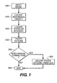
- the reference object is placed in a patient's mouth, such that the reference object defines a start location on the dental target.
- An image of the reference object and dental target is then captured and digitized to provide a digital dental image.
- the input dental image is processed to locate the reference object (610) and a dental target (620).
- the dental target is a tooth of interest.
- the processed image is displayed to the operator along with a window (630), which is conveniently shown as an outline around the located tooth.
- the operator is given an opportunity to verify that the image is acceptable or to provide user input that indicates an adjustment of the window.
- the locating method can terminate without manual inspection and correction. This approach can be used in a batch processing mode.
- the processed image and window are next saved for use in shade matching or another procedure.
- the reference object is configured so as to be readily detected in the dental image and easily handled by the practitioner.
- the reference object is bitable, that is, the reference object is configured such that the patient can bite upon the reference object to hold the reference object in a required orientation. Suitable materials for this purpose are well known to those of skill in the art.
- the reference object has one or more predetermined size dimensions that are utilized in the locating method.
- the reference object used is a rectangular-shaped, uniformly colored block.
- the reference object has a rectangular front face having a known length and width. The ratio of length to width is 3 to 1.
- the front face is flat and has a uniform tone-scale value.
- a more complexly configured reference object can be utilized, but such complexity is unnecessary for the procedures discussed here and could be a source of error.
- Multiple reference objects of different sizes can be utilized, but this required the practitioner to identify the reference object used, or requires use of an automatically recognizable identification feature (such as a different length to width ratio), or the like.
- the reference object defines a start location on the dental target when the dental image is captured.
- the start location is set by the practitioner, by positioning a locating feature of the reference object in a predetermined relationship to the dental target.
- a simple locating feature and simple relationship of that feature to the dental target are preferred for ease of use.
- the locating feature is an imaginary line parallel to the transverse edges of the reference object at the longitudinal center of the reference object.
- the locating feature is the right edge of the reference object. (“Right" refers to the relative position in the dental image.)
- An alternative approach is user of a locating feature in the form of a discontinuity or marking on the reference object or use of a reference object having different length longitudinal edges. With this approach the orientation of the reference object can be recognized so as to identify whether the dental target is above or below the locating feature.
- the start location on the dental target is at a predetermined distance from the reference object in a direction defined by the locating feature. This takes into account any gap between the dental target and the locating feature of the reference object due to tooth geometry or the like. Since the size of one or more dimensions of the reference object are known, the distance and direction, referred to herein as the "initializing vector", can be appropriately scaled in the dental image.
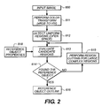
- the reference object is segmented in the dental image to provide a segmented object.
- the segmentation procedure used can be one of a variety of pixel-based, edge-based, region-based types of segmenting methods.
- the input digital image (600) is first converted from sRGB metric to HSI metric (611) using a proper color transform well known in the art where HSI stands for Hue-Saturation-Intensity (See Gonzalez and Woods, Digital Image Processing, pp. 229-235, Addison-Wesley, 1992).
- spatially contiguous smooth regions that is, open space regions, are evaluated (613) to check for pre-determined properties of the reference object (618) in the open space regions (614).
- a useful property of a uniform reference object is a particular tone scale value or range of values that take into account non-uniformities of the capture process. If the reference object is not found after the above steps, an additional step is used to perform region cutting for large regions of complex shapes (615). This may be necessary if the reference object closely matches neighboring teeth, such that the open space region initially detected includes both the reference object and one or more touching teeth.
- a manual input can be required at this stage to identify a portion of the open space region that includes the reference object.
- the reference object can be configured to avoid this occurrence.
- a region cutting process can be used to decompose a large open space region into multiple subregions that can then be evaluated in the same manner as the earlier regions.
- segmented object (627) (also referred to as the detected reference object), shown in the figures as an outline.
- the segmented object is fully defined by the spatial coordinates of the corners of the front face.
- the location and size of the detected reference object (627) is used to set (621) the initial location and size of the dental target for an active shape model (ASM).
- ASM active shape model
- an operator can define the location and size of the dental target by manually providing spatial coordinates of at least two nodes of said window to-said active shape model. This can be done by clicking a button of a mouse with the cursor positioned over the dental target or by designating a dental target by tooth number, or the like.
- a window that includes the start location is then segmented in the dental image.
- the window is the size of the dental target.
- Different segmenting procedures known to those of skill in the art, can be applied here, such as pixel-based, edge-based, region-based, and model-based segmentation procedures.
- ASM Active shape models
- simple segmentation methods such as region growing are sensitive to the above factors even if an operator provides a starting point ("seed") for region growing because there is no mechanism to constrain the shape of the region; frequently region growing would spill to neighboring objects with similar color (e.g., other teeth, the reference object, or the gum).
- Region growing is also sensitive to the threshold used to control the growing process and in general a fixed threshold cannot deal with the color variations from image to image.
- An example of an active shape model is disclosed in "Active Shape Models - Their Training and Application,” Cootes et al., Computer Vision and Image Understanding, Vol. 61, No. 1, pp. 38-59, (1995).
- An example of region growing segmentation applicable to such an active shape model is disclosed in Digital Image Processing, Gonzalez and Woods, pp.458-461, Addison-Wesley, (1992).
- the active shape model technique of the Cootes et al. article determines the locations of feature points by performing a series of local searches for positions with matching textural appearance, with constraining of the results based on a global model of plausible shapes. Texture and shape models are integrated. This is a convenient feature for dental imaging.
- the feature locations of the examples are aligned and arranged into 1-dimensional coordinate vectors.
- the eigenvalues indicate the variance of the examples along the corresponding eigenvector.
- the majority of the shape variation can typically be explained with relatively few of the primary axes. A convenient simplification is retaining only the M most significant axes that encapsulate 99% of the shape variation.
- the final model consists of the mean shape ( x ⁇ ), the primary axes ( v k ), and their expected ranges ⁇ k .
- the shape model constrains the results of the local searches to positions that form a plausible global shape.
- the shape coefficients are then limited to a multiple of their expected ranges and the transformations are inverted.
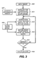
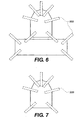
- the ASM is initialized (621) in the preferred embodiment by aligning the mean position of the nodes in the training examples (810) with the location and size of the located reference object (627) using the shape nodes that indicate the reference object (720).
- a search process is then performed to find the match between the ASM and local image structures in terms of texture (622) and shape (623) according to the trained ASM (628).
- the local neighborhoods around each node are investigated to find the positions that best matches the texture model (830).
- the resulting positions are then constrained to form a plausible shape using the shape model (820). This process repeats until the positions of the nodes converge upon a stable result (624).
- the final outline of the tooth is generated (625) consisting of the spatial coordinates of the corners ("nodes") of the ASM.
- the ASM needs to be designed with expert knowledge of the segmentation task, e.g., the characteristics of the object and the background clutter.
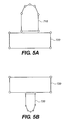
- two ASMs shown in Figures 5A-5B are used.
- Each ASM includes the reference object and the dental target.
- Figure 5A is for an upper tooth, where the tooth of interest (710) is above the reference object (720).
- Figure 5B is for a lower tooth, where the tooth of interest (730) is below the reference object (720).
- the main reason to have two ASMs for upper and lower teeth is that an ASM, once trained, are not easily transconfigurable (e.g., to handle vertical flipping).
- the appropriate ASM can be selected by operator input or use of an appropriately configured reference object. Either way, the vertical positioning of the tooth relative to the reference object can be determined. In addition, for teeth other than the front ones, it may be necessary to either train the ASM using examples of these teeth, or train different ASMs for teeth that are significantly different in their shape (e.g., the canines).
- the ASM can have the reference object and the tooth grouped together or can be limited to only the tooth.
- the relative position and the relative size of the tooth with respect to the reference object would need to be encoded and specified in some other way, for example, by using heuristic rules. It would also be necessary to provide manually the spatial coordinates of at least two nodes for the active shape model of the tooth in order to provide the initial position and size of tooth for the active shape model.
- An ASM consists of nodes.
- nodes should be placed on the points of large curvature, i.e., corners, on the outline of the object because such corners characterize a shape, as shown in Figures 5A-5B.
- narrow rectangular boxes 999 drawn in dotted lines, are placed such that they are centered at the nodes and oriented along the normal direction of the object outline. These boxes are used to analyze the texture characteristics of the interior and exterior of the object.
- the interior side of a each box is expected to be bright (corresponding to tooth color) while the exterior side of a box can be dark (for gaps between teeth) or red/pink (for gum) depending on the location of the box.
- the active shape model encodes such texture characteristics as probability distributions (derived from the training stage, as described below).
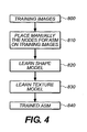
- the ASM needs to be parameterized through a training procedure illustrated in Figure 4.
- a sufficient number of training images (800) need to be collected.
- the more nodes an ASM consists of the more training images are needed to adequately train the ASM.
- an operator needs to place manually the same nodes defined in the ASM on the targets in the training images (820).
- the relative spatial relationships among the nodes are learned to form the shape model (820), while at the same time the color variations near the nodes are learned to form the texture model (830).
- It is preferred to form a multi-resolution texture model by using a series of boxes of different sizes in order to encode texture properties at different scales.
- the trained ASM model (840) learns to cope with normal variations in terms of color, texture and shape.
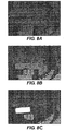
- Figures 7A-7B show an example of the process of locating the reference object.
- uniform colored regions are detected in Figure 7A, where a spatially contiguous region is marked by the same brightness value. Because the reference object is merged with a cluster of teeth in the same smooth region, the initial attempt for locating the reference object fails.
- the region cutting procedure is invoked to separate the reference object from the cluster of teeth and the results are shown in Figure 7B. Since the reference object is already separated, the evaluation process successfully located the reference object, as shown by the brightest region in Figure 7C.
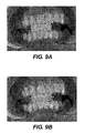
- Figure 8A shows an example of the process of locating a tooth of interest.
- the nodes of the ASM properly resized based on the size of the detected reference object, are placed in the input digital image as shown in Figure 8A.
- Figure 8B shows the final positions of the ASM nodes after the search is converged.
- the tooth nodes shown in white circles, are now accurately placed on the tooth.
- the texture search boxes are also shown in gray rectangles in Figure 8B.
- the spatial coordinates of the tooth nodes are then passed on to the subsequent stages of the dental shade matching system.
- a computer program product may include one or more storage media, for example; magnetic storage media such as magnetic disk (such as a floppy disk) or magnetic tape; optical storage media such as optical disk, optical tape, or machine readable bar code; solid-state electronic storage devices such as random access memory (RAM), or read-only memory (ROM); or any other physical device or media employed to store a computer program having instructions for controlling one or more computers to practice the method according to the present invention.
- magnetic storage media such as magnetic disk (such as a floppy disk) or magnetic tape
- optical storage media such as optical disk, optical tape, or machine readable bar code
- solid-state electronic storage devices such as random access memory (RAM), or read-only memory (ROM); or any other physical device or media employed to store a computer program having instructions for controlling one or more computers to practice the method according to the present invention.
- the system of the invention includes a programmable computer having a microprocessor, computer memory, and a computer program stored in said computer memory for performing the steps of the method.
- the computer has a memory interface operatively connected to the microprocessor. This can be a port, such as a USB port, over a drive that accepts removable memory, or some other device that allows access to camera memory.
- the system includes a digital camera that has memory that is compatible with the memory interface. A photographic film camera and scanner can be used in place of the digital camera, if desired.
- the system also includes a bitable reference object, as earlier described.
- a graphical user interface (GUI) and user input unit, such as a mouse and keyboard can be provided as part of the computer.
- GUI graphical user interface
Landscapes
- Physics & Mathematics (AREA)
- Engineering & Computer Science (AREA)
- Spectroscopy & Molecular Physics (AREA)
- General Physics & Mathematics (AREA)
- Computer Vision & Pattern Recognition (AREA)
- Theoretical Computer Science (AREA)
- Software Systems (AREA)
- Dental Tools And Instruments Or Auxiliary Dental Instruments (AREA)
- Processing Or Creating Images (AREA)
- Image Generation (AREA)
Applications Claiming Priority (2)
| Application Number | Priority Date | Filing Date | Title |
|---|---|---|---|
| US10/731,231 US7463757B2 (en) | 2003-12-09 | 2003-12-09 | Tooth locating within dental images |
| PCT/US2004/039276 WO2005062007A1 (en) | 2003-12-09 | 2004-11-22 | Tooth locating within dental images |
Publications (2)
| Publication Number | Publication Date |
|---|---|
| EP1692474A1 EP1692474A1 (en) | 2006-08-23 |
| EP1692474B1 true EP1692474B1 (en) | 2007-03-21 |
Family
ID=34634311
Family Applications (1)
| Application Number | Title | Priority Date | Filing Date |
|---|---|---|---|
| EP04811913A Expired - Lifetime EP1692474B1 (en) | 2003-12-09 | 2004-11-22 | Tooth locating within dental images |
Country Status (5)
| Country | Link |
|---|---|
| US (2) | US7463757B2 (enExample) |
| EP (1) | EP1692474B1 (enExample) |
| JP (1) | JP2007516745A (enExample) |
| DE (1) | DE602004005496T2 (enExample) |
| WO (1) | WO2005062007A1 (enExample) |
Families Citing this family (33)
| Publication number | Priority date | Publication date | Assignee | Title |
|---|---|---|---|---|
| US7362890B2 (en) * | 2001-05-24 | 2008-04-22 | Astra Tech Inc. | Registration of 3-D imaging of 3-D objects |
| US20040166462A1 (en) | 2003-02-26 | 2004-08-26 | Align Technology, Inc. | Systems and methods for fabricating a dental template |
| SE530196C2 (sv) * | 2004-09-30 | 2008-03-25 | Nobel Biocare Ab | Förfarande och anordning för att åstadkomma färgsättning eller nyansering av protetik samt sådan protetik |
| US7736313B2 (en) * | 2004-11-22 | 2010-06-15 | Carestream Health, Inc. | Detecting and classifying lesions in ultrasound images |
| US7773789B2 (en) * | 2005-08-30 | 2010-08-10 | Siemens Medical Solutions Usa, Inc. | Probabilistic minimal path for automated esophagus segmentation |
| US7440540B2 (en) * | 2006-10-05 | 2008-10-21 | Bassel Kano | Stereoscopic x-ray system and method |
| US20080153054A1 (en) * | 2006-12-22 | 2008-06-26 | Masters James G | Shine Guide for Dental Surfaces and Method of Evaluating Shine of a Dental Surface |
| JP2008185354A (ja) * | 2007-01-26 | 2008-08-14 | Nec Corp | 色識別装置および色識別方法 |
| US8987702B2 (en) | 2007-05-01 | 2015-03-24 | Micron Technology, Inc. | Selectively conducting devices, diode constructions, constructions, and diode forming methods |
| US8092215B2 (en) | 2008-05-23 | 2012-01-10 | Align Technology, Inc. | Smile designer |
| DE202008014344U1 (de) | 2008-10-28 | 2010-03-25 | Edinger-Strobl, Verena, Mag. DDr. | Gebissbild-Simulationsvorrichtung |
| CN102054091A (zh) * | 2009-11-09 | 2011-05-11 | 无锡时代天使医疗器械科技有限公司 | 制造用于调整牙齿位置的牙科器械的方法 |
| FI129779B (fi) * | 2010-07-19 | 2022-08-31 | Palodex Group Oy | Menetelmä ja laite intraoraalikuvan käsittelemiseksi |
| US20130034823A1 (en) * | 2011-08-02 | 2013-02-07 | Rongguang Liang | Adaptive illumination method and apparatus for dental shade matching |
| US10942022B2 (en) * | 2012-12-20 | 2021-03-09 | Philips Image Guided Therapy Corporation | Manual calibration of imaging system |
| US9855114B2 (en) * | 2013-05-21 | 2018-01-02 | Carestream Health, Inc. | Method and system for user interaction in 3-D cephalometric analysis |
| FR3010629B1 (fr) | 2013-09-19 | 2018-02-16 | Dental Monitoring | Procede de controle du positionnement de dents |
| US9478043B2 (en) * | 2014-01-29 | 2016-10-25 | Abdullaibrahim Abdulwaheed | Measuring teeth whiteness system and method |
| FR3027505B1 (fr) | 2014-10-27 | 2022-05-06 | H 43 | Procede de controle du positionnement de dents |
| FR3027504B1 (fr) | 2014-10-27 | 2022-04-01 | H 43 | Procede de controle du positionnement de dents |
| FR3027507B1 (fr) | 2014-10-27 | 2016-12-23 | H 42 | Procede de controle de la dentition |
| DE102015212806A1 (de) | 2015-07-08 | 2017-01-12 | Sirona Dental Systems Gmbh | System und Verfahren zum Scannen von anatomischen Strukturen und zum Darstellen eines Scanergebnisses |
| US11457998B2 (en) | 2016-07-29 | 2022-10-04 | Ivoclar Vivadent Ag | Recording device |
| CN109717966B (zh) * | 2017-10-27 | 2021-04-30 | 华硕电脑股份有限公司 | 用于牙齿整形的影像仿真方法及其影像仿真装置 |
| US10547780B2 (en) | 2018-05-14 | 2020-01-28 | Abdul Abdulwaheed | Body part color measurement detection and method |
| CA3100495A1 (en) | 2018-05-16 | 2019-11-21 | Benevis Informatics, Llc | Systems and methods for review of computer-aided detection of pathology in images |
| US11094085B2 (en) * | 2018-08-23 | 2021-08-17 | Ivoclar Vivadent Ag | System comprising a color selection aid and a method for determining tooth colors |
| CN109793482B (zh) * | 2019-01-07 | 2022-06-21 | 苏州佳世达光电有限公司 | 口腔扫描装置及其控制方法 |
| CN112132163B (zh) * | 2020-09-21 | 2024-04-02 | 杭州睿琪软件有限公司 | 识别对象边缘的方法、系统及计算机可读存储介质 |
| US12496173B2 (en) | 2020-11-17 | 2025-12-16 | James R. Glidewell Dental Ceramics, Inc. | Method for coloring a dental prosthesis |
| US20230386682A1 (en) * | 2022-05-26 | 2023-11-30 | Abdullalbrahim ABDULWAHEED | Systems and methods to chronologically image orthodontic treatment progress |
| CN114748201B (zh) * | 2022-04-19 | 2024-06-25 | 深圳广成创新技术有限公司 | 一种牙科种植体的三维参数的获取方法、装置 |
| CN115661172A (zh) * | 2022-11-08 | 2023-01-31 | 福州海狸家口腔科技有限公司 | 一种牙齿图像分割方法、存储介质和电子设备 |
Family Cites Families (13)
| Publication number | Priority date | Publication date | Assignee | Title |
|---|---|---|---|---|
| DE68918274T2 (de) * | 1989-06-27 | 1995-05-04 | Gendex Corp | Phantom für ein zahnärztliches Panorama-Röntgengerät. |
| US5766006A (en) * | 1995-06-26 | 1998-06-16 | Murljacic; Maryann Lehmann | Tooth shade analyzer system and methods |
| US5901245A (en) | 1997-01-23 | 1999-05-04 | Eastman Kodak Company | Method and system for detection and characterization of open space in digital images |
| IL120426A0 (en) * | 1997-03-12 | 1997-07-13 | Fradkin Boris | Teeth color measurement system |
| US6190170B1 (en) * | 1998-05-05 | 2001-02-20 | Dentech, Llc | Automated tooth shade analysis and matching system |
| US6206691B1 (en) * | 1998-05-20 | 2001-03-27 | Shade Analyzing Technologies, Inc. | System and methods for analyzing tooth shades |
| EP1043959A4 (en) * | 1998-11-03 | 2003-07-02 | Shade Analyzing Technologies Inc | INTERACTIVE DENTAL RESTAURATION NETWORK |
| US6328567B1 (en) * | 1999-01-21 | 2001-12-11 | Dentech, Llc | Method, apparatus and system for automated tooth shade analysis and matching |
| US7234937B2 (en) * | 1999-11-30 | 2007-06-26 | Orametrix, Inc. | Unified workstation for virtual craniofacial diagnosis, treatment planning and therapeutics |
| US20020021439A1 (en) | 2000-08-07 | 2002-02-21 | Derek Priestley | Colour matching system |
| US20030143509A1 (en) * | 2002-01-29 | 2003-07-31 | Cadent, Ltd. | Method and system for assisting in applying an orthodontic treatment |
| AU2003223391A1 (en) | 2002-03-28 | 2003-10-13 | Color Savvy Systems Limited | Method for segmenting an image |
| US7064830B2 (en) | 2003-06-12 | 2006-06-20 | Eastman Kodak Company | Dental color imaging system |
-
2003
- 2003-12-09 US US10/731,231 patent/US7463757B2/en not_active Expired - Fee Related
-
2004
- 2004-11-22 DE DE602004005496T patent/DE602004005496T2/de not_active Expired - Lifetime
- 2004-11-22 EP EP04811913A patent/EP1692474B1/en not_active Expired - Lifetime
- 2004-11-22 WO PCT/US2004/039276 patent/WO2005062007A1/en not_active Ceased
- 2004-11-22 JP JP2006543851A patent/JP2007516745A/ja active Pending
-
2008
- 2008-10-21 US US12/254,916 patent/US7751606B2/en not_active Expired - Fee Related
Also Published As
| Publication number | Publication date |
|---|---|
| US20050123180A1 (en) | 2005-06-09 |
| EP1692474A1 (en) | 2006-08-23 |
| DE602004005496D1 (de) | 2007-05-03 |
| US20090042168A1 (en) | 2009-02-12 |
| US7463757B2 (en) | 2008-12-09 |
| WO2005062007A1 (en) | 2005-07-07 |
| DE602004005496T2 (de) | 2007-11-29 |
| JP2007516745A (ja) | 2007-06-28 |
| US7751606B2 (en) | 2010-07-06 |
Similar Documents
| Publication | Publication Date | Title |
|---|---|---|
| EP1692474B1 (en) | Tooth locating within dental images | |
| CN114424246B (zh) | 用于配准口内测量的方法、系统和计算机可读存储介质 | |
| US7672530B2 (en) | Method and system for identifying illumination flux in an image | |
| JP4997252B2 (ja) | 画像内の照明域を識別する方法 | |
| US20240366340A1 (en) | Method for generating a model of a dental arch | |
| US12251278B2 (en) | Dental shade matching for multiple anatomical regions | |
| Carter et al. | Automated quantification of dental plaque accumulation using digital imaging | |
| CN114365184A (zh) | 用于检测三维测量中的错误的方法、系统和计算机可读存储介质 | |
| CN112912933B (zh) | 用于口腔内3d扫描的方法和口腔内成像装置 | |
| CN117152507B (zh) | 一种牙齿健康状态检测方法、装置、设备及存储介质 | |
| US8983183B2 (en) | Spatially varying log-chromaticity normals for use in an image process | |
| US20110222742A1 (en) | Pipeline for generating an intrinsic image | |
| Mansoor et al. | A statistical modeling approach to computer-aided quantification of dental biofilm | |
| CN115760934B (zh) | 一种眼鼻三角区的自动标定方法 | |
| EP1754193A1 (en) | An image processing apparatus, an imaging system, a computer program and a method for scaling an object in an image | |
| JP3710802B2 (ja) | 歯牙材料色調選択支援プログラム及び歯牙材料色調選択支援方法 | |
| JPH11306325A (ja) | 対象物検出装置及び対象物検出方法 | |
| US8842907B2 (en) | Method for performing a multi-clustering merge for use in an image process | |
| US8849018B2 (en) | Log-chromaticity clustering pipeline for use in an image process | |
| CN115147659A (zh) | 一种植物果实外表面dus测试性状的图像分析方法及系统 | |
| Luo et al. | Automatic target segmentation in color dental images | |
| US8811732B2 (en) | Weighted entropy minimization for optimizing a log-chromaticity normal for use in an image process | |
| EP4393449A1 (en) | Method and system for tooth wear detection | |
| WO2024256348A1 (en) | Method and system for detection of dental plaque | |
| CN119745549A (zh) | 用于口内扫描的系统、方法和装置 |
Legal Events
| Date | Code | Title | Description |
|---|---|---|---|
| PUAI | Public reference made under article 153(3) epc to a published international application that has entered the european phase |
Free format text: ORIGINAL CODE: 0009012 |
|
| 17P | Request for examination filed |
Effective date: 20060529 |
|
| AK | Designated contracting states |
Kind code of ref document: A1 Designated state(s): DE FI FR |
|
| GRAP | Despatch of communication of intention to grant a patent |
Free format text: ORIGINAL CODE: EPIDOSNIGR1 |
|
| GRAS | Grant fee paid |
Free format text: ORIGINAL CODE: EPIDOSNIGR3 |
|
| GRAA | (expected) grant |
Free format text: ORIGINAL CODE: 0009210 |
|
| AK | Designated contracting states |
Kind code of ref document: B1 Designated state(s): DE FI FR |
|
| DAX | Request for extension of the european patent (deleted) | ||
| RBV | Designated contracting states (corrected) |
Designated state(s): DE FI FR |
|
| REF | Corresponds to: |
Ref document number: 602004005496 Country of ref document: DE Date of ref document: 20070503 Kind code of ref document: P |
|
| ET | Fr: translation filed | ||
| RAP2 | Party data changed (patent owner data changed or rights of a patent transferred) |
Owner name: CARESTREAM HEALTH, INC. |
|
| PLBE | No opposition filed within time limit |
Free format text: ORIGINAL CODE: 0009261 |
|
| STAA | Information on the status of an ep patent application or granted ep patent |
Free format text: STATUS: NO OPPOSITION FILED WITHIN TIME LIMIT |
|
| 26N | No opposition filed |
Effective date: 20071227 |
|
| REG | Reference to a national code |
Ref country code: FR Ref legal event code: TP |
|
| PGFP | Annual fee paid to national office [announced via postgrant information from national office to epo] |
Ref country code: DE Payment date: 20131129 Year of fee payment: 10 Ref country code: FR Payment date: 20131025 Year of fee payment: 10 |
|
| PGFP | Annual fee paid to national office [announced via postgrant information from national office to epo] |
Ref country code: FI Payment date: 20131105 Year of fee payment: 10 |
|
| REG | Reference to a national code |
Ref country code: DE Ref legal event code: R119 Ref document number: 602004005496 Country of ref document: DE |
|
| PG25 | Lapsed in a contracting state [announced via postgrant information from national office to epo] |
Ref country code: FI Free format text: LAPSE BECAUSE OF NON-PAYMENT OF DUE FEES Effective date: 20141122 |
|
| REG | Reference to a national code |
Ref country code: FR Ref legal event code: ST Effective date: 20150731 |
|
| PG25 | Lapsed in a contracting state [announced via postgrant information from national office to epo] |
Ref country code: DE Free format text: LAPSE BECAUSE OF NON-PAYMENT OF DUE FEES Effective date: 20150602 |
|
| PG25 | Lapsed in a contracting state [announced via postgrant information from national office to epo] |
Ref country code: FR Free format text: LAPSE BECAUSE OF NON-PAYMENT OF DUE FEES Effective date: 20141201 |