EP1690708B1 - Motor vehicle air vent with vanes installed in a rotary cylindrical body - Google Patents
Motor vehicle air vent with vanes installed in a rotary cylindrical body Download PDFInfo
- Publication number
- EP1690708B1 EP1690708B1 EP06290202A EP06290202A EP1690708B1 EP 1690708 B1 EP1690708 B1 EP 1690708B1 EP 06290202 A EP06290202 A EP 06290202A EP 06290202 A EP06290202 A EP 06290202A EP 1690708 B1 EP1690708 B1 EP 1690708B1
- Authority
- EP
- European Patent Office
- Prior art keywords
- cylindrical body
- predetermined
- air vent
- housing
- vanes
- Prior art date
- Legal status (The legal status is an assumption and is not a legal conclusion. Google has not performed a legal analysis and makes no representation as to the accuracy of the status listed.)
- Expired - Fee Related
Links
Images

Classifications
-
- B—PERFORMING OPERATIONS; TRANSPORTING
- B60—VEHICLES IN GENERAL
- B60H—ARRANGEMENTS OF HEATING, COOLING, VENTILATING OR OTHER AIR-TREATING DEVICES SPECIALLY ADAPTED FOR PASSENGER OR GOODS SPACES OF VEHICLES
- B60H1/00—Heating, cooling or ventilating [HVAC] devices
- B60H1/34—Nozzles; Air-diffusers
- B60H1/3414—Nozzles; Air-diffusers with means for adjusting the air stream direction
- B60H1/3435—Nozzles; Air-diffusers with means for adjusting the air stream direction using only a pivoting frame
Landscapes
- Physics & Mathematics (AREA)
- Thermal Sciences (AREA)
- Engineering & Computer Science (AREA)
- Mechanical Engineering (AREA)
- Air-Flow Control Members (AREA)
- Air-Conditioning For Vehicles (AREA)
Description
La présente invention concerne un aérateur destiné à introduire un flux d'air dans l'habitacle d'un véhicule, notamment d'une automobile, comprenant un boîtier comportant une ouverture axiale reliée à une arrivée d'air conditionné et une ouverture latérale débouchant dans l'habitacle du véhicule, et des moyens de réglage pour modifier la direction du flux d'air sortant de l'ouverture latérale du boîtier.The present invention relates to an aerator for introducing a flow of air into the passenger compartment of a vehicle, in particular an automobile, comprising a housing having an axial opening connected to a conditioned air inlet and a lateral opening opening into the passenger compartment of the vehicle, and adjusting means for changing the direction of the air flow out of the lateral opening of the housing.
Les aérateurs des véhicules automobiles actuels comportent généralement de nombreuses pièces constitutives, ce qui les rend difficiles et coûteux à fabriquer, un tel dispositif est connu du document
Leurs moyens de réglage ont en outre une structure élémentaire ne permettant pas de diriger dans une direction prédéterminée précise le flux d'air pénétrant dans l'habitacle des véhicules.Their adjustment means also have an elementary structure that does not make it possible to direct the flow of air entering the passenger compartment of the vehicles in a predetermined precise direction.
La présente invention se propose de remédier à ces inconvénients et, pour ce faire, elle a pour objet un aérateur ayant la structure présentée au premier paragraphe ci-dessus et qui est caractérisé en ce que les moyens de réglage comprennent un corps cylindrique monté rotatif axialement dans le boîtier et dont la paroi latérale est définie par des ailettes parallèles à son axe longitudinal, ces ailettes étant disposées symétriquement par rapport à un plan diamétral prédéterminé du corps cylindrique et présentant par rapport à ce plan des inclinaisons variant progressivement.The present invention proposes to remedy these drawbacks and, for this purpose, it relates to an aerator having the structure presented in the first paragraph above and which is characterized in that the adjustment means comprise a cylindrical body mounted axially rotatable in the housing and whose side wall is defined by fins parallel to its longitudinal axis, these fins being arranged symmetrically with respect to a predetermined diametral plane of the cylindrical body and having, with respect to this plane, gradually varying inclinations.
Cet aérateur a une structure particulièrement simple puisque les ailettes sont solidaires du corps cylindrique et constituent donc une pièce unique avec celui-ci.This aerator has a particularly simple structure since the fins are integral with the cylindrical body and therefore constitute a single piece with it.
Il permet en outre de régler avec précision la direction du flux d'air pénétrant dans l'habitacle du véhicule, ce réglage dépendant de l'angle de rotation du corps cylindrique.It also makes it possible to precisely adjust the direction of the air flow entering the passenger compartment of the vehicle, this adjustment being dependent on the angle of rotation of the cylindrical body.
Par ailleurs, comme les ailettes présentent les unes par rapport aux autres des inclinaisons différentes, le débit du flux d'air incident peut dans une certaine mesure être réglé en fonction de l'angle de rotation du corps cylindrique.Furthermore, since the fins have different inclinations relative to each other, the flow rate of the incident air flow can to a certain extent be adjusted according to the angle of rotation of the cylindrical body.
De préférence, le corps cylindrique comporte deux ailettes extrêmes dont les plans médians longitudinaux forment des angles de respectivement 0 et 90° avec le plan diamétral prédéterminé.Preferably, the cylindrical body comprises two end fins whose longitudinal median planes form angles of respectively 0 and 90 ° with the predetermined diametral plane.
Le débit du flux d'air admis dans l'habitacle du véhicule peut ainsi être maximum lorsque l'ailette extrême parallèle au plan diamétral prédéterminé est devant l'ouverture latérale du boîtier et minimum lorsque l'autre ailette extrême est devant cette ouverture.The flow rate of the air flow admitted into the passenger compartment of the vehicle can thus be maximum when the extreme fin parallel to the predetermined diametral plane is in front of the lateral opening of the housing and minimum when the other extreme fin is in front of this opening.
Selon un mode de réalisation particulier du corps cylindrique, les côtés longitudinaux des ailettes délimitent des cercles interne et externe pratiquement tangents au niveau de l'ailette extrême dont le plan longitudinal médian forme un angle de 90° avec le plan diamétral prédéterminé.According to a particular embodiment of the cylindrical body, the longitudinal sides of the fins delimit internal and external circles substantially tangent at the level of the extreme fin whose median longitudinal plane forms an angle of 90 ° with the predetermined diametral plane.
L'émission du flux d'air dans l'habitacle du véhicule peut ainsi être complètement interrompue lorsque l'ailette extrême formant un angle de 90° avec le plan diamétral prédéterminé et les ailettes adjacentes à cette ailette extrême sont devant l'ouverture latérale du boîtier.The emission of the air flow in the passenger compartment of the vehicle can thus be completely interrupted when the extreme fin forming an angle of 90 ° with the predetermined diametral plane and the fins adjacent to this extreme fin are in front of the lateral opening of the housing.
Selon le mode de réalisation particulier ci-dessus, les plans médians longitudinaux des ailettes situées de part et d'autre du plan diamétral prédéterminé forment avec ce dernier des angles différents, la valeur d'un angle (α) pour une ailette prédéterminée étant égale à la moitié de celle de l'angle (β) formé, pour cette aile prédéterminée, par deux rayons prédéterminés du cercle externe, à savoir le rayon situé dans le plan médian longitudinal de l'ailette extrême qui forme un angle nul avec le plan diamétral prédéterminé et le rayon coupant l'axe longitudinal de ladite ailette prédéterminée.According to the particular embodiment above, the longitudinal median planes of the fins located on either side of the predetermined diametral plane form with the latter different angles, the value of an angle (α) for a predetermined fin being equal at half that of the angle (β) formed, for this predetermined wing, by two predetermined radii of the outer circle, namely the radius located in the longitudinal median plane of the extreme fin which forms a zero angle with the plane predetermined diameter and the radius intersecting the longitudinal axis of said predetermined fin.
Par ailleurs, le corps cylindrique peut avantageusement porter un organe de commande faisant saillie dans l'habitacle, à proximité de l'ouverture axiale du boîtier.Furthermore, the cylindrical body may advantageously carry a control member protruding into the passenger compartment, near the axial opening of the housing.
Un passager situé à proximité de l'aérateur peut ainsi régler la direction et le débit du flux d'air pénétrant dans l'habitacle en actionnant l'organe de commande.A passenger located near the aerator can thus adjust the direction and flow of the air flow entering the cabin by actuating the control member.
Cet organe peut être un disque solidaire de l'une des extrémités du corps cylindrique et s'étendant coaxialement avec ce dernier.This member may be a disc integral with one end of the cylindrical body and extending coaxially with the latter.
Il suffit donc dans ce cas de faire tourner le disque pour régler la direction du flux d'air.In this case it is sufficient to rotate the disc to adjust the direction of the air flow.
Afin de faciliter la mise en rotation du corps cylindrique, la périphérie du disque peut être crantée.In order to facilitate the rotation of the cylindrical body, the periphery of the disk may be notched.
Par ailleurs, pour limiter le poids de l'aérateur et permettre la fabrication de celui-ci en grande série dans des conditions économiques compétitives, le boîtier et le corps cylindrique sont de préférence réalisés en matière plastique.Furthermore, to limit the weight of the aerator and allow the manufacture thereof in large series under competitive economic conditions, the housing and the cylindrical body are preferably made of plastic.
Un mode d'exécution de la présente invention sera décrit ci-après à titre d'exemple nullement limitatif en référence aux dessins annexés dans lesquels :
- la
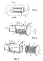
figure 1 est une vue de face schématique montrant un aérateur conforme à l'invention, cet aérateur étant installé derrière un cache fixé sur le tableau de bord d'un véhicule automobile ; - la
figure 2 est une vue en perspective schématique de l'aérateur ; - la
figure 3 est une vue en perspective éclatée de l'aérateur visible sur lafigure 2 ; - la
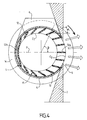
figure 4 est une vue en coupe selon la ligne IV-IV de lafigure 1 ; et - les
figures 5 à 7 sont des vues analogues à lafigure 4 mais montrant le corps cylindrique dans des positions différentes.
- the
figure 1 is a diagrammatic front view showing an aerator according to the invention, this aerator being installed behind a cover fixed on the dashboard of a motor vehicle; - the
figure 2 is a schematic perspective view of the aerator; - the
figure 3 is an exploded perspective view of the visible aerator on thefigure 2 ; - the
figure 4 is a sectional view along line IV-IV of thefigure 1 ; and - the
Figures 5 to 7 are similar views to thefigure 4 but showing the cylindrical body in different positions.
L'aérateur représenté sur les dessins a été conçu pour être installé sur le tableau de bord d'une automobile.The aerator shown in the drawings was designed to be installed on the dashboard of an automobile.
Il va de soi cependant que l'on ne sortirait pas du cadre de la présente invention si cet aérateur était installé sur le panneau intérieur d'une portière ou sur tout autre support situé dans l'habitacle de l'automobile. Il pourrait également être utilisé pour diffuser de l'air dans l'habitacle d'un véhicule de transport tel qu'un avion ou un wagon.It goes without saying, however, that it would not be outside the scope of the present invention if this aerator was installed on the interior panel of a door or on any other support located in the passenger compartment of the automobile. It could also be used to distribute air in the passenger compartment of a transport vehicle such as an airplane or a wagon.
L'aérateur visible sur les dessins comprend un boîtier 1 situé derrière un cache 2 fixé d'une manière connue en soi dans un évidement ménagé dans le tableau de bord 3.The aerator visible in the drawings comprises a
Le boîtier 1 comporte une paroi cylindrique 4 pourvue d'une ouverture latérale 5, une première paroi transversale 6 pourvue d'une ouverture axiale 7 reliée par un conduit approprié 8 à l'installation de climatisation non représentée de l'automobile, et une seconde paroi transversale 9 pourvue d'une ouverture axiale 10 dont le rôle sera précisé ci-après.The
Les parois transversales 6 et 9 sont parallèles et solidaires de la paroi cylindrique 4 qui s'étend entre elles.The
Comme le montre la
L'aérateur comprend également un corps cylindrique 11 monté rotatif axialement dans le boîtier 1, l'introduction du corps 11 dans le boîtier 1 étant assurée à travers l'ouverture axiale 10 de la paroi transversales 9 de ce dernier.The aerator also comprises a
Le corps cylindrique 11 comporte une paroi latérale définie par des ailettes 12 s'étendant parallèlement à son axe longitidunal.The
Il comporte également deux parois transversales, l'une étant pourvue d'un orifice 13 situé devant l'ouverture axiale 7 du boîtier 1, et l'autre étant constitué par un disque 14 dont le diamètre est supérieur à celui du corps 11.It also comprises two transverse walls, one being provided with an
En se référant aux
On remarquera également la présence de deux ailettes extrêmes 12a, 12b dont les plans médians longitudinaux forment des angles de respectivement 0 et 90° avec le plan diamétral P.It will also be noted the presence of two
Dans le mode de réalisation représenté, les côtés longitudinaux des ailettes 12 délimitent un cercle interne C1 et un cercle externe C2, ces cercles étant pratiquement tangents au niveau de l'ailette extrême 12b.In the embodiment shown, the longitudinal sides of the
Comme le montre la
On notera ici que le disque 14 constituant l'une des deux parois transversales du corps 11 fait saillie dans une lumière ménagée dans le cache 2, à proximité de l'orifice de celui-ci qui est situé devant l'ouverture latérale 5 du boîtier 1.It should be noted here that the
La périphérie du disque 14 est crantée afin qu'un passager du véhicule puisse plus facilement faire tourner le corps cylindrique 11 à l'aide d'un doigt.The periphery of the
Grâce aux crans ménagés sur la périphérie du disque, l'adhérence du doigt utilisé pour faire tourner le corps 11 est en effet augmentée de façon sensible.Thanks to the notches formed on the periphery of the disc, the grip of the finger used to rotate the
On précisera enfin que le boîtier 1 et le corps cylindrique 11 sont réalisés en matière plastique et que des joints d'étanchéité sont prévus pour éviter des fuites d'air entre le boîtier 1 et le corps cylindrique 11.Finally, it will be specified that the
L'aérateur qui vient d'être décrit est installé horizontalement sur le tableau du bord 3 et permet de diriger le flux d'air entrant dans l'habitacle du véhicule dans de très nombreuses directions dirigées vers le haut, comme représenté sur la
En faisant tourner d'un angle prédéterminé, dans un sens ou dans l'autre, le corps cylindrique 11 dans le boîtier 1, un passager du véhicule peut donc diriger le flux d'air vers le haut ou vers le bas dans une direction particulière précise.By rotating a predetermined angle, in one direction or the other, the
Quand ce passager fait tourner le corps cylindrique 11 de façon à amener l'ailette extrême 12a dans la partie centrale de l'ouverture latérale 5 du boîtier 1, comme représenté sur la
En revanche, quand il fait tourner le corps cylindrique 11 de façon à amener l'ailette extrême 12b et les ailettes adjacentes à celle-ci dans la partie centrale de l'ouverture latérale 5 du boîtier, comme représenté sur la
L'aérateur qui vient d'être décrit pourrait bien entendu être installé verticalement sur le tableau de bord.The aerator just described could of course be installed vertically on the dashboard.
Dans ce cas, le flux d'air pourrait entrer dans l'habitacle dans de très nombreuses directions dirigées vers la droite ou vers la gauche.In this case, the airflow could enter the passenger compartment in very many directions directed to the right or to the left.
Par ailleurs, le disque 14 prévu pour faire tourner manuellement le corps cylindrique 11 dans le boîtier 1 pourrait être remplacé par un organe de commande motorisé.Furthermore, the
Claims (6)
- An air vent intended to introduce an airflow into the passenger compartment of a vehicle, in particular a car, comprising a housing (1) including an axial opening (7) connected to an air-conditioning inlet and a lateral opening (5) opening into the passenger compartment of the vehicle, and control means (11) for modifying the direction of the introduction of the airflow into the passenger compartment, the control means comprising a cylindrical body (11) mounted to rotate about its longitudinal axis in the housing (1) and including a lateral wall defined by vanes (12) of gradually varying inclination extending parallel to the said longitudinal axis, characterised in that the vanes (12) are disposed symmetrically in relation to a predetermined diametral plane (P) of the cylindrical body (11), this plane cutting through two end vanes (12a, 12b) and forming angles of 0° and 90° respectively therewith, the longitudinal sides of the vanes (12) delimiting internal (C1) and external (C2) circles virtually tangential at the end vane (12b), the median longitudinal plane of which forms an angle of 90° with the predetermined diametral plane (P).
- An air vent according to claim 1, characterised in that the median longitudinal planes of the vanes (12) situated on either side of the predetermined diametral plane (P) form different angles (α) therewith, the value of an angle (α) for one predetermined vane being equal to half that of the angle (β) formed for this predetermined vane by two predetermined radii of the external circle (C2), namely the radius situated in the median longitudinal plane of the end vane (12a) forming a zero angle with the predetermined diametral plane (P) and the radius intersecting the longitudinal axis of the said predetermined vane.
- An air vent according to claim 1 or claim 2, characterised in that the cylindrical body (11) is provided with a control element (14) projecting into the passenger compartment in the vicinity of the axial opening (5) of the housing (1),
- An air vent according to claim 3, characterised in that the control element is a disc (14) integral with one of the ends of the cylindrical body (11) and extending coaxially with the latter.
- An air vent according to claim 4, characterised in that the periphery of the disc (14) is notched.
- An air vent according to any one of the preceding claims, characterised in that the housing (1) and the cylindrical body (11) are made of plastic.
Applications Claiming Priority (1)
| Application Number | Priority Date | Filing Date | Title |
|---|---|---|---|
| FR0501382A FR2881992B1 (en) | 2005-02-11 | 2005-02-11 | AERATOR FOR VEHICLE COMPRISING FINS CARRIED BY A ROTARY CYLINDRICAL BODY |
Publications (2)
| Publication Number | Publication Date |
|---|---|
| EP1690708A1 EP1690708A1 (en) | 2006-08-16 |
| EP1690708B1 true EP1690708B1 (en) | 2009-03-25 |
Family
ID=34953899
Family Applications (1)
| Application Number | Title | Priority Date | Filing Date |
|---|---|---|---|
| EP06290202A Expired - Fee Related EP1690708B1 (en) | 2005-02-11 | 2006-02-06 | Motor vehicle air vent with vanes installed in a rotary cylindrical body |
Country Status (3)
| Country | Link |
|---|---|
| EP (1) | EP1690708B1 (en) |
| DE (1) | DE602006005853D1 (en) |
| FR (1) | FR2881992B1 (en) |
Families Citing this family (1)
| Publication number | Priority date | Publication date | Assignee | Title |
|---|---|---|---|---|
| FR3061872B1 (en) * | 2017-01-19 | 2020-11-27 | Valeo Systemes Thermiques | AERATOR WITH DYNAMIC DIFFUSION FOR A MOTOR VEHICLE |
Family Cites Families (3)
| Publication number | Priority date | Publication date | Assignee | Title |
|---|---|---|---|---|
| DE2902998C2 (en) * | 1979-01-26 | 1983-10-20 | Bayerische Motoren Werke AG, 8000 München | Ventilation device for the interior of a motor vehicle |
| DE3044289A1 (en) * | 1980-11-25 | 1982-06-24 | Audi Nsu Auto Union Ag, 7107 Neckarsulm | Adjustable fresh air duct for vehicle interior - has rotating cylinder with fixed vanes at different angles |
| DE60313376D1 (en) * | 2002-03-15 | 2007-05-31 | Trw Automotive Electron & Comp | Ventilation nozzle for ventilation systems |
-
2005
- 2005-02-11 FR FR0501382A patent/FR2881992B1/en not_active Expired - Fee Related
-
2006
- 2006-02-06 DE DE602006005853T patent/DE602006005853D1/en active Active
- 2006-02-06 EP EP06290202A patent/EP1690708B1/en not_active Expired - Fee Related
Also Published As
| Publication number | Publication date |
|---|---|
| FR2881992A1 (en) | 2006-08-18 |
| EP1690708A1 (en) | 2006-08-16 |
| FR2881992B1 (en) | 2010-10-08 |
| DE602006005853D1 (en) | 2009-05-07 |
Similar Documents
| Publication | Publication Date | Title |
|---|---|---|
| EP1814752B1 (en) | Ventilator flap for a ventilation system in a vehicle cabin | |
| FR2892993A1 (en) | Aerodynamic device for e.g. minivan, has deflector displaced by tilting between retracted position in which deflector is applied on external surface of plate and active position in which deflector is projected with respect to plate | |
| EP3727913B1 (en) | Compact coanda effect ventilation device for motor vehicle incorporating a control module provided with a control panel | |
| EP1506910B1 (en) | Aerodynamic device for a vehicle; vehicle equipped with such a device | |
| EP3887182B1 (en) | Coanda-effect thin air vent for a motor vehicle | |
| FR2892994A1 (en) | Aerodynamic system for e.g. mini van, has assembly having plate fixed on body element by fastening, screwing and riveting, where plate includes case containing deflector displaceable between retracted and projected active position | |
| EP1580053B1 (en) | Improved air outlet for passenger compartments of automotive vehicles and dashboard equipped with such an outlet. | |
| EP1690708B1 (en) | Motor vehicle air vent with vanes installed in a rotary cylindrical body | |
| EP1690709B1 (en) | Air vent for vehicles with pivoting vanes and rotating vanes, especially for an automobile | |
| EP1749682A1 (en) | Air nozzle, in particular for a vehicle, with pivotable air guiding louvers mounted on a rotatable body | |
| EP1632423A1 (en) | Aerodynamic system for a motor vehicle and motor vehicle comprising such a system. | |
| FR2706818A1 (en) | ||
| EP1872988B1 (en) | Ventilator for automobile comprising two sets of adjustment blades | |
| FR2863946A1 (en) | Breather for motor vehicle, has spheroidal unit presenting front surface separated from back surface, where front surface slides against inner edge of circular opening of dashboard | |
| EP3257730B1 (en) | Rear portion of a motor vehicle with conduit and associated motor vehicle | |
| WO2019170985A1 (en) | Lever for a motor vehicle shut-off device | |
| EP1705041B1 (en) | Vehicle nozzle having directing blades, each having a driving rod actuated by one rotary wheel | |
| EP3524524B1 (en) | Dynamic air intake, environmental control device, engine and vehicle equipped with such an intake | |
| EP4051909B1 (en) | Motor support and hvac (heating, ventilating and/or airconditioning) device for automobile vehicle | |
| EP3587223B1 (en) | Motor vehicle including an air guiding device comprising a fixed part and a mobile part | |
| FR3067319B1 (en) | MECHANISM FOR DEPLOYING A SET OF VORTEX GENERATORS | |
| WO2009022082A2 (en) | Arrangement for fastening two adjacent bodywork elements | |
| WO1997028038A1 (en) | Dashboard for vehicle, for example motor vehicles capable of diffusing an air flow into the occupants space of said vehicle | |
| FR3062087B1 (en) | AERATOR, IN PARTICULAR FOR A MOTOR VEHICLE | |
| FR2484045A1 (en) | Air distributor for vehicle heating - has rotating drum with two curved blades to direct air through ports in housing |
Legal Events
| Date | Code | Title | Description |
|---|---|---|---|
| PUAI | Public reference made under article 153(3) epc to a published international application that has entered the european phase |
Free format text: ORIGINAL CODE: 0009012 |
|
| AK | Designated contracting states |
Kind code of ref document: A1 Designated state(s): AT BE BG CH CY CZ DE DK EE ES FI FR GB GR HU IE IS IT LI LT LU LV MC NL PL PT RO SE SI SK TR |
|
| AX | Request for extension of the european patent |
Extension state: AL BA HR MK YU |
|
| 17P | Request for examination filed |
Effective date: 20070205 |
|
| 17Q | First examination report despatched |
Effective date: 20070319 |
|
| AKX | Designation fees paid |
Designated state(s): DE FR |
|
| GRAP | Despatch of communication of intention to grant a patent |
Free format text: ORIGINAL CODE: EPIDOSNIGR1 |
|
| GRAS | Grant fee paid |
Free format text: ORIGINAL CODE: EPIDOSNIGR3 |
|
| GRAA | (expected) grant |
Free format text: ORIGINAL CODE: 0009210 |
|
| AK | Designated contracting states |
Kind code of ref document: B1 Designated state(s): DE FR |
|
| REF | Corresponds to: |
Ref document number: 602006005853 Country of ref document: DE Date of ref document: 20090507 Kind code of ref document: P |
|
| PLBE | No opposition filed within time limit |
Free format text: ORIGINAL CODE: 0009261 |
|
| STAA | Information on the status of an ep patent application or granted ep patent |
Free format text: STATUS: NO OPPOSITION FILED WITHIN TIME LIMIT |
|
| 26N | No opposition filed |
Effective date: 20091229 |
|
| REG | Reference to a national code |
Ref country code: FR Ref legal event code: PLFP Year of fee payment: 11 |
|
| REG | Reference to a national code |
Ref country code: FR Ref legal event code: PLFP Year of fee payment: 12 |
|
| REG | Reference to a national code |
Ref country code: FR Ref legal event code: PLFP Year of fee payment: 13 |
|
| PGFP | Annual fee paid to national office [announced via postgrant information from national office to epo] |
Ref country code: DE Payment date: 20190222 Year of fee payment: 14 |
|
| PGFP | Annual fee paid to national office [announced via postgrant information from national office to epo] |
Ref country code: FR Payment date: 20190226 Year of fee payment: 14 |
|
| REG | Reference to a national code |
Ref country code: DE Ref legal event code: R119 Ref document number: 602006005853 Country of ref document: DE |
|
| PG25 | Lapsed in a contracting state [announced via postgrant information from national office to epo] |
Ref country code: DE Free format text: LAPSE BECAUSE OF NON-PAYMENT OF DUE FEES Effective date: 20200901 Ref country code: FR Free format text: LAPSE BECAUSE OF NON-PAYMENT OF DUE FEES Effective date: 20200229 |