EP1690708B1 - Luftaustritt für Kraftfahrzeuge mit an einem drehbaren zylinderförmigen Körper angebrachten Luftleitschaufeln - Google Patents
Luftaustritt für Kraftfahrzeuge mit an einem drehbaren zylinderförmigen Körper angebrachten Luftleitschaufeln Download PDFInfo
- Publication number
- EP1690708B1 EP1690708B1 EP06290202A EP06290202A EP1690708B1 EP 1690708 B1 EP1690708 B1 EP 1690708B1 EP 06290202 A EP06290202 A EP 06290202A EP 06290202 A EP06290202 A EP 06290202A EP 1690708 B1 EP1690708 B1 EP 1690708B1
- Authority
- EP
- European Patent Office
- Prior art keywords
- cylindrical body
- predetermined
- air vent
- housing
- vanes
- Prior art date
- Legal status (The legal status is an assumption and is not a legal conclusion. Google has not performed a legal analysis and makes no representation as to the accuracy of the status listed.)
- Ceased
Links
Images

Classifications
-
- B—PERFORMING OPERATIONS; TRANSPORTING
- B60—VEHICLES IN GENERAL
- B60H—ARRANGEMENTS OF HEATING, COOLING, VENTILATING OR OTHER AIR-TREATING DEVICES SPECIALLY ADAPTED FOR PASSENGER OR GOODS SPACES OF VEHICLES
- B60H1/00—Heating, cooling or ventilating devices
- B60H1/34—Nozzles; Air-diffusers
- B60H1/3414—Nozzles; Air-diffusers with means for adjusting the air stream direction
- B60H1/3435—Nozzles; Air-diffusers with means for adjusting the air stream direction using only a pivoting frame
Definitions
- the present invention relates to an aerator for introducing a flow of air into the passenger compartment of a vehicle, in particular an automobile, comprising a housing having an axial opening connected to a conditioned air inlet and a lateral opening opening into the passenger compartment of the vehicle, and adjusting means for changing the direction of the air flow out of the lateral opening of the housing.
- the aerators of current motor vehicles generally have many component parts, which makes them difficult and expensive to manufacture, such a device is known from the document DE 3044289 A1 .
- Their adjustment means also have an elementary structure that does not make it possible to direct the flow of air entering the passenger compartment of the vehicles in a predetermined precise direction.
- the present invention proposes to remedy these drawbacks and, for this purpose, it relates to an aerator having the structure presented in the first paragraph above and which is characterized in that the adjustment means comprise a cylindrical body mounted axially rotatable in the housing and whose side wall is defined by fins parallel to its longitudinal axis, these fins being arranged symmetrically with respect to a predetermined diametral plane of the cylindrical body and having, with respect to this plane, gradually varying inclinations.
- This aerator has a particularly simple structure since the fins are integral with the cylindrical body and therefore constitute a single piece with it.
- the fins have different inclinations relative to each other, the flow rate of the incident air flow can to a certain extent be adjusted according to the angle of rotation of the cylindrical body.
- the cylindrical body comprises two end fins whose longitudinal median planes form angles of respectively 0 and 90 ° with the predetermined diametral plane.
- the flow rate of the air flow admitted into the passenger compartment of the vehicle can thus be maximum when the extreme fin parallel to the predetermined diametral plane is in front of the lateral opening of the housing and minimum when the other extreme fin is in front of this opening.
- the longitudinal sides of the fins delimit internal and external circles substantially tangent at the level of the extreme fin whose median longitudinal plane forms an angle of 90 ° with the predetermined diametral plane.
- the emission of the air flow in the passenger compartment of the vehicle can thus be completely interrupted when the extreme fin forming an angle of 90 ° with the predetermined diametral plane and the fins adjacent to this extreme fin are in front of the lateral opening of the housing.
- the longitudinal median planes of the fins located on either side of the predetermined diametral plane form with the latter different angles, the value of an angle ( ⁇ ) for a predetermined fin being equal at half that of the angle ( ⁇ ) formed, for this predetermined wing, by two predetermined radii of the outer circle, namely the radius located in the longitudinal median plane of the extreme fin which forms a zero angle with the plane predetermined diameter and the radius intersecting the longitudinal axis of said predetermined fin.
- cylindrical body may advantageously carry a control member protruding into the passenger compartment, near the axial opening of the housing.
- a passenger located near the aerator can thus adjust the direction and flow of the air flow entering the cabin by actuating the control member.
- This member may be a disc integral with one end of the cylindrical body and extending coaxially with the latter.
- the periphery of the disk may be notched.
- the housing and the cylindrical body are preferably made of plastic.
- the aerator shown in the drawings was designed to be installed on the dashboard of an automobile.
- this aerator was installed on the interior panel of a door or on any other support located in the passenger compartment of the automobile. It could also be used to distribute air in the passenger compartment of a transport vehicle such as an airplane or a wagon.
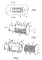
- the aerator visible in the drawings comprises a housing 1 located behind a cover 2 fixed in a manner known per se in a recess provided in the dashboard 3.
- the casing 1 comprises a cylindrical wall 4 provided with a lateral opening 5, a first transverse wall 6 provided with an axial opening 7 connected by a suitable duct 8 to the air conditioning installation, not shown of the automobile, and a second transverse wall 9 provided with an axial opening 10 whose role will be specified below.
- the transverse walls 6 and 9 are parallel and integral with the cylindrical wall 4 which extends between them.
- the cover 2 has an orifice located in front of the lateral opening 5 and having dimensions slightly smaller than those of this opening.
- the aerator also comprises a cylindrical body 11 rotatably mounted axially in the housing 1, the introduction of the body 11 into the housing 1 being provided through the axial opening 10 of the transverse wall 9 of the latter.
- the cylindrical body 11 has a side wall defined by fins 12 extending parallel to its longitudinal axis.
- It also comprises two transverse walls, one being provided with an orifice 13 situated in front of the axial opening 7 of the casing 1, and the other consisting of a disc 14 whose diameter is greater than that of the body 11.
- the fins 12 are arranged symmetrically with respect to a predetermined diametral plane P of the body 11 and have progressively varying inclinations with respect to this plane.
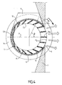
- the longitudinal sides of the fins 12 delimit an inner circle C1 and an outer circle C2, these circles being substantially tangent at the level of the extreme fin 12b.
- the longitudinal median planes of the fins 12 located on either side of the diametral plane P form with the latter different angles ⁇ , the a value of an angle ⁇ for a predetermined fin being equal to half that of the angle ⁇ formed, for this predetermined fin, by two predetermined radii of the circle C2, namely the radius situated in the longitudinal median plane of the extreme fin 12a and the radius intersecting the longitudinal axis of said predetermined fin.
- the disc 14 constituting one of the two transverse walls of the body 11 projects into a slot in the cover 2, close to the opening thereof which is located in front of the lateral opening 5 of the housing 1.
- the periphery of the disk 14 is notched so that a passenger of the vehicle can more easily rotate the cylindrical body 11 with the aid of a finger.
- the grip of the finger used to rotate the body 11 is in fact significantly increased.
- housing 1 and the cylindrical body 11 are made of plastic and that seals are provided to prevent air leakage between the housing 1 and the cylindrical body 11.
- the aerator which has just been described is installed horizontally on the board of the board 3 and makes it possible to direct the flow of air entering the cabin of the vehicle in a very many directions directed upwards, as represented on the figure 5 and many directions down, as shown on the figure 6 .
- a passenger of the vehicle can therefore direct the airflow upward or downward in a particular direction precise.
- the aerator just described could of course be installed vertically on the dashboard.
- the airflow could enter the passenger compartment in very many directions directed to the right or to the left.
- the disc 14 provided for manually rotating the cylindrical body 11 in the housing 1 could be replaced by a motorized control member.
Landscapes
- Physics & Mathematics (AREA)
- Thermal Sciences (AREA)
- Engineering & Computer Science (AREA)
- Mechanical Engineering (AREA)
- Air-Flow Control Members (AREA)
- Air-Conditioning For Vehicles (AREA)
Claims (6)
- Luftdüse zum Einlass eines Luftstromes in den Innenraum eines Fahrzeuges, insbesondere eines Kraftfahrzeuges, bestehend aus einem Gehäuse (1) mit einer an eine Zufuhr für aufbereitete Luft angeschlossenen axialen Öffnung (7) und mit einer in den Innenraum des Fahrzeuges mündenden Seitenöffnung (5), und aus Einstellungsmitteln (11) zur Änderung der Einlassrichtung des Luftstroms in den Innenraum, wobei die Einstellungsmittel einen Zylinderkörper (11) umfassen, der im Gehäuse (1) um seine Längsachse drehgelagert ist, und der eine von Flügeln (12) gebildete Seitenwand aufweist, welche parallel zur Längsachse verlaufen und sich stufenweise ändernde Neigungen aufweisen,
dadurch gekennzeichnet, dass die Flügel (12) bezüglich einer vorbestimmten Diametralebene (P) des Zylinderkörpers (11) symmetrisch angeordnet sind, wobei diese Ebene zwei endseitige Flügel (12a, 12b) schneidet und dabei mit letzteren einen Winkel von 0 bzw. 90° bildet, und wobei die Längsseiten der Flügel (12) einen inneren Kreis (C1) und einen äußeren Kreis (C2) abgrenzen, die an jenem endseitigen Flügel (12b) im wesentlichen aneinander berühren, dessen Längsmittelachse einen Winkel von 90° mit der vorbestimmten Diametralebene (P) bildet. - Luftdüse nach Anspruch 1, dadurch gekennzeichnet, dass die Längsmittelebenen der beidseits der vorbestimmten Diametralebene (P) liegenden Flügel (12) mit dieser Ebene unterschiedliche Winkel (α) bilden, wobei der Wert eines Winkels (α) für einen vorbestimmten Flügel zweimal so klein wie der Wert des Winkels (β) ist, der für diesen vorbestimmten Flügel von zwei vorbestimmten Radien des äußeren Kreises (C2) gebildet ist, nämlich von dem Radius, der in der Längsmittelebene jenes endseitigen Flügels (12a) liegt, der mit der vorbestimmten Diametralebene (P) einen Nullwinkel bildet, und von dem Radius, der die Längsachse des vorbestimmten Flügels schneidet.
- Luftdüse nach Anspruch 1 oder 2, dadurch gekennzeichnet, dass der Zylinderkörper (11) ein in der Nähe der axialen Öffnung (5) des Gehäuses (1) in den Innenraum vorspringendes Steuerglied (14) trägt.
- Luftdüse nach Anspruch 3, dadurch gekennzeichnet, dass das Steuerglied eine mit dem einen Ende des Zylinderkörpers (11) einstückig verbundene, mit diesem koaxial angeordnete Kreisscheibe (14) ist.
- Luftdüse nach Anspruch 4, dadurch gekennzeichnet, dass der Umfang der Kreisscheibe (14) mit Kerben versehen ist.
- Luftdüse nach einem der vorhergehenden Ansprüche, dadurch gekennzeichnet, dass das Gehäuse (1) und der Zylinderkörper (11) aus Kunststoff hergestellt sind.
Applications Claiming Priority (1)
| Application Number | Priority Date | Filing Date | Title |
|---|---|---|---|
| FR0501382A FR2881992B1 (fr) | 2005-02-11 | 2005-02-11 | Aerateur pour vehicule comprenant des ailettes portees par un corps cylindrique rotatif |
Publications (2)
| Publication Number | Publication Date |
|---|---|
| EP1690708A1 EP1690708A1 (de) | 2006-08-16 |
| EP1690708B1 true EP1690708B1 (de) | 2009-03-25 |
Family
ID=34953899
Family Applications (1)
| Application Number | Title | Priority Date | Filing Date |
|---|---|---|---|
| EP06290202A Ceased EP1690708B1 (de) | 2005-02-11 | 2006-02-06 | Luftaustritt für Kraftfahrzeuge mit an einem drehbaren zylinderförmigen Körper angebrachten Luftleitschaufeln |
Country Status (3)
| Country | Link |
|---|---|
| EP (1) | EP1690708B1 (de) |
| DE (1) | DE602006005853D1 (de) |
| FR (1) | FR2881992B1 (de) |
Families Citing this family (1)
| Publication number | Priority date | Publication date | Assignee | Title |
|---|---|---|---|---|
| FR3061872B1 (fr) * | 2017-01-19 | 2020-11-27 | Valeo Systemes Thermiques | Aerateur a diffusion dynamique pour un vehicule automobile |
Family Cites Families (3)
| Publication number | Priority date | Publication date | Assignee | Title |
|---|---|---|---|---|
| DE2902998C2 (de) * | 1979-01-26 | 1983-10-20 | Bayerische Motoren Werke AG, 8000 München | Belüftungsvorrichtung für den Innenraum eines Kraftfahrzeuges |
| DE3044289A1 (de) * | 1980-11-25 | 1982-06-24 | Audi Nsu Auto Union Ag, 7107 Neckarsulm | Belueftungsduese, insbesondere fuer den fahrgastraum eines fahrzeuges |
| ATE359929T1 (de) * | 2002-03-15 | 2007-05-15 | Trw Automotive Electron & Comp | Belüftungsdüse für lüftungssysteme |
-
2005
- 2005-02-11 FR FR0501382A patent/FR2881992B1/fr not_active Expired - Fee Related
-
2006
- 2006-02-06 DE DE602006005853T patent/DE602006005853D1/de not_active Expired - Lifetime
- 2006-02-06 EP EP06290202A patent/EP1690708B1/de not_active Ceased
Also Published As
| Publication number | Publication date |
|---|---|
| EP1690708A1 (de) | 2006-08-16 |
| FR2881992B1 (fr) | 2010-10-08 |
| DE602006005853D1 (de) | 2009-05-07 |
| FR2881992A1 (fr) | 2006-08-18 |
Similar Documents
| Publication | Publication Date | Title |
|---|---|---|
| EP1814752B1 (de) | Ventilatorklappe für ein ventilationssystem in einer fahrzeugkabine | |
| EP3727913B1 (de) | Kompakte lüftungsvorrichtung mit coanda-effekt für ein kraftfahrzeug mit einem mit einer bedienungstafel versehenen steuermodul | |
| EP1506910B1 (de) | Aerodynamische Vorrichtung für ein Fahrzeug; Fahrzeug mit einer solchen aerodynamischen Vorrichtung | |
| EP3887182B1 (de) | Dünne belüftung mit coanda-effekt für ein kraftfahrzeug | |
| EP3702189B1 (de) | Belüftungsvorrichtung für fahrzeug | |
| FR2892993A1 (fr) | Dispositif aerodynamique pour un vehicule automobile et vehicule automobile comportant au moins un tel dispositif aerodynamique. | |
| WO2019170985A1 (fr) | Levier pour un dispositif d'obturation de vehicule automobile | |
| EP1690708B1 (de) | Luftaustritt für Kraftfahrzeuge mit an einem drehbaren zylinderförmigen Körper angebrachten Luftleitschaufeln | |
| EP1332900A1 (de) | Luftausströmer, insbesondere eines Kraftfahrzeuges | |
| FR2505010A1 (fr) | Dispositif pour la commande d'un appareil de chauffage et de degivrage de vehicule automobile | |
| FR3062087B1 (fr) | Aerateur, notamment pour vehicule automobile | |
| FR2892994A1 (fr) | Systeme aerodynamique pour un vehicule automobile et vehicule automobile comportant au moins un tel systeme. | |
| EP3587223B1 (de) | Kraftfahrzeug, das über eine luftführungsvorrichtung verfügt, die einen festen und einen beweglichen teil umfasst | |
| EP1690709B1 (de) | Luftaustritt für Fahrzeuge mit schwenkenden Schaufeln und rotierenden Schaufeln, insbesondere für Automobile | |
| EP1580053B1 (de) | Verbesserte Luftausströmer für Innenräume von Kraftfahrzeugen und Armaturenbrett versehen mit so einem Luftausströmer | |
| FR2706818A1 (de) | ||
| EP1872988B1 (de) | Lüfter für Kraftfahrzeug, das zwei Regulierungsflügelanordnungen umfasst | |
| EP1749682A1 (de) | Luftdüse, insbesondere für ein Kraftfahrzeug, mit schwenkbaren Luftleitlamellen, die auf einem drehbaren Gehäuse montiert sind | |
| EP4051909B1 (de) | Motorträger und heizung-, lüftung- und/oder klimatisierungsgerät für automobiles fahrzeug | |
| EP3524524B1 (de) | Dynamischer lufteinlass, klimaanlage, motor und fahrzeug mit einem solchen einlass ausgestattet | |
| EP1632423A1 (de) | Aerodynamisches System für ein Kraftfahrzeug und Kraftfahrzeug mit einem derartigen System. | |
| EP1705041B1 (de) | Fahrzeugluftausströmer mit Luftführungslamellen, die je mit einem drehscheibengesteuerten Antriebspleuel versehen sind | |
| EP2173604A2 (de) | Anordnung zur befestigung zweier benachbarter karosserie-elemente | |
| WO1997028038A1 (fr) | Tableau de bord pour vehicule, par exemple, des vehicules automobiles, apte a permettre la diffusion de flux d'air dans l'habitacle dudit vehicule | |
| FR2484045A1 (fr) | Distributeur de fluide du type a boisseau tournant |
Legal Events
| Date | Code | Title | Description |
|---|---|---|---|
| PUAI | Public reference made under article 153(3) epc to a published international application that has entered the european phase |
Free format text: ORIGINAL CODE: 0009012 |
|
| AK | Designated contracting states |
Kind code of ref document: A1 Designated state(s): AT BE BG CH CY CZ DE DK EE ES FI FR GB GR HU IE IS IT LI LT LU LV MC NL PL PT RO SE SI SK TR |
|
| AX | Request for extension of the european patent |
Extension state: AL BA HR MK YU |
|
| 17P | Request for examination filed |
Effective date: 20070205 |
|
| 17Q | First examination report despatched |
Effective date: 20070319 |
|
| AKX | Designation fees paid |
Designated state(s): DE FR |
|
| GRAP | Despatch of communication of intention to grant a patent |
Free format text: ORIGINAL CODE: EPIDOSNIGR1 |
|
| GRAS | Grant fee paid |
Free format text: ORIGINAL CODE: EPIDOSNIGR3 |
|
| GRAA | (expected) grant |
Free format text: ORIGINAL CODE: 0009210 |
|
| AK | Designated contracting states |
Kind code of ref document: B1 Designated state(s): DE FR |
|
| REF | Corresponds to: |
Ref document number: 602006005853 Country of ref document: DE Date of ref document: 20090507 Kind code of ref document: P |
|
| PLBE | No opposition filed within time limit |
Free format text: ORIGINAL CODE: 0009261 |
|
| STAA | Information on the status of an ep patent application or granted ep patent |
Free format text: STATUS: NO OPPOSITION FILED WITHIN TIME LIMIT |
|
| 26N | No opposition filed |
Effective date: 20091229 |
|
| REG | Reference to a national code |
Ref country code: FR Ref legal event code: PLFP Year of fee payment: 11 |
|
| REG | Reference to a national code |
Ref country code: FR Ref legal event code: PLFP Year of fee payment: 12 |
|
| REG | Reference to a national code |
Ref country code: FR Ref legal event code: PLFP Year of fee payment: 13 |
|
| PGFP | Annual fee paid to national office [announced via postgrant information from national office to epo] |
Ref country code: DE Payment date: 20190222 Year of fee payment: 14 |
|
| PGFP | Annual fee paid to national office [announced via postgrant information from national office to epo] |
Ref country code: FR Payment date: 20190226 Year of fee payment: 14 |
|
| REG | Reference to a national code |
Ref country code: DE Ref legal event code: R119 Ref document number: 602006005853 Country of ref document: DE |
|
| PG25 | Lapsed in a contracting state [announced via postgrant information from national office to epo] |
Ref country code: DE Free format text: LAPSE BECAUSE OF NON-PAYMENT OF DUE FEES Effective date: 20200901 Ref country code: FR Free format text: LAPSE BECAUSE OF NON-PAYMENT OF DUE FEES Effective date: 20200229 |