EP1688811A2 - Netzwerke für Prozesssteuerung - Google Patents
Netzwerke für Prozesssteuerung Download PDFInfo
- Publication number
- EP1688811A2 EP1688811A2 EP06250640A EP06250640A EP1688811A2 EP 1688811 A2 EP1688811 A2 EP 1688811A2 EP 06250640 A EP06250640 A EP 06250640A EP 06250640 A EP06250640 A EP 06250640A EP 1688811 A2 EP1688811 A2 EP 1688811A2
- Authority
- EP
- European Patent Office
- Prior art keywords
- spur
- bus
- power
- cable
- devices
- Prior art date
- Legal status (The legal status is an assumption and is not a legal conclusion. Google has not performed a legal analysis and makes no representation as to the accuracy of the status listed.)
- Pending
Links
- 238000004886 process control Methods 0.000 title claims abstract description 25
- 238000000034 method Methods 0.000 claims description 13
- 238000002955 isolation Methods 0.000 claims description 6
- 238000004891 communication Methods 0.000 claims description 4
- 230000002411 adverse Effects 0.000 claims description 3
- 230000009471 action Effects 0.000 claims description 2
- 238000012544 monitoring process Methods 0.000 claims 1
- 231100001261 hazardous Toxicity 0.000 description 14
- 238000012545 processing Methods 0.000 description 5
- 230000008901 benefit Effects 0.000 description 2
- 230000005540 biological transmission Effects 0.000 description 2
- 230000015556 catabolic process Effects 0.000 description 2
- 230000003750 conditioning effect Effects 0.000 description 2
- 238000010276 construction Methods 0.000 description 2
- 239000007789 gas Substances 0.000 description 2
- 238000012986 modification Methods 0.000 description 2
- 230000004048 modification Effects 0.000 description 2
- 230000008569 process Effects 0.000 description 2
- 238000012369 In process control Methods 0.000 description 1
- 238000013461 design Methods 0.000 description 1
- 238000010586 diagram Methods 0.000 description 1
- 230000009977 dual effect Effects 0.000 description 1
- 239000002360 explosive Substances 0.000 description 1
- 230000036039 immunity Effects 0.000 description 1
- 238000010965 in-process control Methods 0.000 description 1
- 230000001105 regulatory effect Effects 0.000 description 1
- 230000011664 signaling Effects 0.000 description 1
- 238000012360 testing method Methods 0.000 description 1
Images


Classifications
-
- G—PHYSICS
- G05—CONTROLLING; REGULATING
- G05B—CONTROL OR REGULATING SYSTEMS IN GENERAL; FUNCTIONAL ELEMENTS OF SUCH SYSTEMS; MONITORING OR TESTING ARRANGEMENTS FOR SUCH SYSTEMS OR ELEMENTS
- G05B19/00—Programme-control systems
- G05B19/02—Programme-control systems electric
- G05B19/418—Total factory control, i.e. centrally controlling a plurality of machines, e.g. direct or distributed numerical control [DNC], flexible manufacturing systems [FMS], integrated manufacturing systems [IMS] or computer integrated manufacturing [CIM]
- G05B19/4185—Total factory control, i.e. centrally controlling a plurality of machines, e.g. direct or distributed numerical control [DNC], flexible manufacturing systems [FMS], integrated manufacturing systems [IMS] or computer integrated manufacturing [CIM] characterised by the network communication
- G05B19/41855—Total factory control, i.e. centrally controlling a plurality of machines, e.g. direct or distributed numerical control [DNC], flexible manufacturing systems [FMS], integrated manufacturing systems [IMS] or computer integrated manufacturing [CIM] characterised by the network communication by local area network [LAN], network structure
-
- G—PHYSICS
- G05—CONTROLLING; REGULATING
- G05B—CONTROL OR REGULATING SYSTEMS IN GENERAL; FUNCTIONAL ELEMENTS OF SUCH SYSTEMS; MONITORING OR TESTING ARRANGEMENTS FOR SUCH SYSTEMS OR ELEMENTS
- G05B2219/00—Program-control systems
- G05B2219/30—Nc systems
- G05B2219/31—From computer integrated manufacturing till monitoring
- G05B2219/31157—Star network, hub
-
- G—PHYSICS
- G05—CONTROLLING; REGULATING
- G05B—CONTROL OR REGULATING SYSTEMS IN GENERAL; FUNCTIONAL ELEMENTS OF SUCH SYSTEMS; MONITORING OR TESTING ARRANGEMENTS FOR SUCH SYSTEMS OR ELEMENTS
- G05B2219/00—Program-control systems
- G05B2219/30—Nc systems
- G05B2219/31—From computer integrated manufacturing till monitoring
- G05B2219/31244—Safety, reconnect network automatically if broken
-
- Y—GENERAL TAGGING OF NEW TECHNOLOGICAL DEVELOPMENTS; GENERAL TAGGING OF CROSS-SECTIONAL TECHNOLOGIES SPANNING OVER SEVERAL SECTIONS OF THE IPC; TECHNICAL SUBJECTS COVERED BY FORMER USPC CROSS-REFERENCE ART COLLECTIONS [XRACs] AND DIGESTS
- Y02—TECHNOLOGIES OR APPLICATIONS FOR MITIGATION OR ADAPTATION AGAINST CLIMATE CHANGE
- Y02P—CLIMATE CHANGE MITIGATION TECHNOLOGIES IN THE PRODUCTION OR PROCESSING OF GOODS
- Y02P90/00—Enabling technologies with a potential contribution to greenhouse gas [GHG] emissions mitigation
- Y02P90/02—Total factory control, e.g. smart factories, flexible manufacturing systems [FMS] or integrated manufacturing systems [IMS]
Definitions
- This invention relates to improvements in process control systems.
- Petrochemical processing systems typically locate a number of devices in the field remote from the computer control room.
- sensors such as temperature and pressure gauges are mounted to processing equipment in the field.
- actuators such as valve controllers and pumps, are located in the field.
- These devices generally respond to digital transmission over a wired-bus system connected to one or more computers located in the control room of the petrochemical processing plant.
- the bus system connects the control room equipment with a twisted pair trunk cable.
- the field devices are connected with spur cables to the trunk by a wire terminal block in the field junction box. All of the devices are electrically parallel with the trunk cable.
- the cable carries power to the attached devices and a power conditioner separates the power supply from the signals on the wiring.
- trunk cable itself. If the trunk cable is damaged, the network's operation fails. There are no known systems available in the prior art that eliminate this single point of failure.
- the trunk cable length is limited by the voltage drop that is caused by the resistance of the wires. This limitation depends on the power each device draws from the network. Spur cable lengths are typically less than 120 meters so that the signals on the network are not overly distorted. These considerations require care and expertise in designing the network.
- a process control system utilizes a hub network to connect devices in the field to control room equipment.
- Embodiments include redundant spur cables so that if a spur cable connecting the control room with the remote devices is disabled, this will not disrupt communication or control of the remote devices located in its field.
- the power for operating the remote devices is brought directly to the devices and not sent over the wires from the control room. All of the spurs between the hub and the field instruments and actuators limit the voltage and current levels so as to be intrinsically safe within hazardous areas.
- the power conditioning function of the prior art is eliminated by use of repeaters.
- a short or failure in a remote device or its spur cables will not adversely affect the rest of the system operation
- the spur cables are connected to the hub by resistors which simultaneously (a) protects the hub's delivery of power to the other spur cables if a spur short circuits, (b) limits the power from the hub to the spur for Intrinsinc Safety (IS) purposes, and (c) provides series termination for the signals on the spur cable.
- resistors which simultaneously (a) protects the hub's delivery of power to the other spur cables if a spur short circuits, (b) limits the power from the hub to the spur for Intrinsinc Safety (IS) purposes, and (c) provides series termination for the signals on the spur cable.
- Sensors such as temperature and pressure gauges
- actuators such as valve controllers and pumps
- the sensors and the actuators communicate with each other and with computers located in the control room that operates the plant.
- the communication system and method used a standard local area network for digitally transmitting information over a pair of wires.
- the wires also carry power to the devices.
- This communications method is commonly called fieldbus and is defined in IEC standard 61158-2 and further described in the Fieldbus Wiring Guiding published by Relcom, Inc.
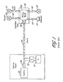
- a common fieldbus configuration is shown in Figure 1.
- a twisted wire pair trunk cable 20 connects the control room equipment 25 with a number of devices 30, 31, 32 and 33 in the field.
- devices 30-31 include instruments for measuring temperatures or pressure and actuators such as remotely activated valves and pumps.
- the wires in the trunk cable 20 are typically in a shielded cable to reduce noise ingress (shield not shown).
- the field devices 30-33 are respectively connected with spur cables 40, 41, 42 and 43 to the trunk by a wire terminal block 50 in a field junction box. All the devices are electrically parallel with the trunk cable 20.
- a terminator (T) 60 is needed at each end of the trunk cable to allow the twisted pair of cable 20 to carry digital signals. Since the cable 20 carries power to the attached devices, a power conditioner (C) 70 is needed to separate a conventional constant voltage power supply (P) 75 from the signals on the wiring. This type of a network configuration is called a bus.
- Fieldbus devices signal by consuming a variable amount of current from the spur cable. For example, a quiescent fieldbus device draws 20 mA current from the network. When the device signals, it draws alternately between 10 and 30 mA. Thus, the peak-to-peak signaling current is 20 mA.
- fieldbus terminators 60 are used to provide a load so that the varying signal current is turned into a voltage. The terminators 60 also terminate signal reflections at the ends of the trunk cable.
- Another disadvantage of the bus configuration of Figure 1 is that failure of the power supply 75 or its associated power conditioner will result in turning off the power to all the devices on the bus. This problem can be minimized by providing redundant power supplies and redundant power conditioners such that each can supply power to the network. If there is a failure in one of them, an alarm is generated and the failed unit replaced while the other one is working.
- trunk cable 20 itself. If the trunk cable 20 is damaged, the network's operation fails.
- the trunk cable length is limited by the voltage drop that is caused by the resistance of the wires. This limitation depends on the power each device draws from the network. Spur cable lengths are typically less than 120 meters so that the signals on the network are not overly distorted. These considerations require care and expertise in designing the prior art networks.
- the novel process control network illustrated in Figures 2-5 does not have the disadvantages of the bus networks described above and shown in Figure 1.
- a hub network 100 is utilized and the trunk cable 20 of the prior art is eliminated. Rather, control room equipment 125 in the control room is connected by a spur cable 130 to the hub network 100. All of the devices 30, 31, 32 and 33 are also connected to the hub network 100 by the respective spurs 40, 41, 42 and 43.
- a particular advantage of the illustrated embodiment is that one or more redundant spurs enable redundant connections to be made between the hub network 100 and the equipment 125 in the control room. Further, as further described below, the power for operation of the 30-33 remote devices and for the hub network 100 is brought directly from a power source 150 and not sent over fieldbus wires from the control room.
- the components of the hub network 100 are shown in Figure 3.
- the input power 151 from power source 150 is converted by its power supply 200 to a regulated DC voltage and connected as shown at 152 to an internal power bus 205.
- This power is used by each of the spur circuits 210, 211 that are connected between the power bus and a respective spur cable 40, 41, 42, 43, 130, 135.
- each spur circuit 210, 211 Internal to each spur circuit 210, 211 is a repeater circuit (shown in Figure 5 at 225, 226).
- the function of a repeater circuit is to receive a signal coming from a spur cable and put it on the internal data bus 215. All the other repeater circuits in the other spur circuits take the signal from this data bus 215 and transmit it on the spur cables to their respective devices.
- spur circuits 210, 211 While two spur circuits 210, 211 are shown, many spur circuits will typically be used in a hub 100 as needed for the number of remote devices in this field.
- the hub 100 advantageously provides Intrinsic Safety (IS) protection for hazardous areas that have explosive atmospheres.
- IS Intrinsic Safety
- the IS technique prevents the equipment used in these hazardous areas from igniting the atmosphere.
- IS requires that the electrical power sent into the hazardous area be limited. This is achieved by galvanically isolating the electrical power coming from non-hazardous areas and limiting the voltage and current that can be sent into the hazardous area. Galvanic isolation is further described in the Fieldbus Wiring Guide published by Relcom, Inc. These requirements are defined by international standards. Equipment used in hazardous areas is certified by various agencies to meet these requirements.
- Figures 4 and 5 illustrate the manner in which the IS requirements are met by the hub 100.
- the galvanic isolation circuit 250 provides galvanic isolation and regulates its output voltage to a given DC value. Under normal conditions, the voltage is less than the breakdown voltage of the triple-redundant Zener diodes 260, 261, 262. If the voltage regulation does not work and a voltage higher than the Zener breakdown voltage is produced, a large output current results and the fuse 270 will blow. In any case, the output voltage on terminals 275, 276 to the hazardous area will never exceed a maximum value.
- the ISR resistor 310 limits the current that can be drawn by equipment in the hazardous area.
- the hub's power supply shown in Figure 4 provides galvanic isolation from the input power and limits the voltage sent to the spur circuits.
- the limited voltage is distributed on the power bus 205 to the spur circuits.
- the voltage from the power bus 205 passes through ISR current-limiting resistors 310, 311, 312 and 313 in each Spur circuit to its spur cable.
- the diagram shows a resistor on both wires of the spur cable, e.g., resistors 310, 311. This is not an IS requirement but are used for balancing the impedance to the spur cable.
- the current limiting resistors enable a fail-safe system since if any of the remote devices 30, 31, 32 or 33 short circuits its associated spur cable 40, 41, 42 and 43, the current limited resistors limit the current to the faulty device and do not adversely affect operation of any of the other remotely connected devices.
- Repeaters 225, 226 are respectively coupled to transmitters (T) 320, 321 that send signals to the spur and to receivers (R) 325, 326 that receive signals from the spur. These transmitters and receivers are also connected to the spur wires through resistors 350, 351, 352, 353, 354, 355, 356 and 357. Thus, in case a transmitter or receiver fails, the power to the spur is limited.
- Resistors 310, 311, 312 and 313, have a dual function and eliminate the necessity of the prior art terminators 60 shown in Figure 1.
- these power limiting resistors 310, 311, 312 and 313 also provide the function of a terminator:
- the current signal propagates over the spur cable to the current limiting resistors and is terminated.
- the current limiting resistors are chosen to match the characteristic impedance of the cable.
- the hub's spur circuit transmits, the signal travels to the device at the end of the spur cable. Since the device has a high impedance, the signal reflects back to the spur circuit and is terminated by the current limiting resistors.
- the resistors connecting a spur cable to the power bus 205 such as resistors 310, 311 can be combined into a single resistor used on either the positive or negative lead of the spur cable.
- the negative lead of the spur cable is connected directly to bus 205 whereas the positive lead is connected through a resistor 315 having a resistance equal to the sum of the resistance of resistors 310 and 311.
- another embodiment connects the positive lead directly to the bus 205 and the negative lead is connected through resistor 315.
- inventions of Figures 5, 6, and 7 all provide for simultaneous protection of (a) the hub's power on bus 205 from short circuits on any spur, (b) limiting power from the hub to the spur for intrinsic safety (IS) purposes, and (c) provide series termination for signals on the spur cable by choosing the resistor value at, or close to, the characteristic impedance of the spur cable.
- the spur cables are series-terminated by the current limiting resistors which obviates the need to have dedicated terminators 60 of Figure 1 installed on the spur cables.
- the hub 100 also provides a way to test the devices and spur cables. If a repeater does not receive the periodically expected signal from its spur cable, its corresponding device is either malfunctioning or the spur cable is open circuited. If the voltage at the output of the spur circuit is lower than expected, the device or the spur cable is shorted.
- a circuit can be used to detect if either of the wires is shorted to the cable shield. This is not a critical error but reduces the noise immunity of the cable. These error conditions are advantageously indicated by a light on the spur circuit to aid in locating the problem. The error condition is also indicated electrically on the common alarm bus in the hub.
- the hub's alarm circuit monitors the alarm bus 400 and the condition of the power supply.
- the alarm circuit senses problems, it uses a standard fieldbus message to send the error condition over the network:
- One device on the network is designated as the Link Active Scheduler, or LAS 500 as shown in Figure 2.
- One of the LAS's functions is to poll each device on the network, one at a time, by sending a Token message.
- a device receives a Token addressed to it, it can use the bus to send messages on the network, including alarm messages.
- the alarm circuit 390 in the hub acts as a fieldbus device. When it receives a Token, it sends its alarm status message over the network. It then sends a Return Token message that indicates that it is finished using the network. The alarm message is received by another device on the network that takes the appropriate action.
- the IS resistors limit the current each spur can draw.
- the spurs between the hub and the fieldbus device can be long. This eliminates the spur length limitation of the bus topology fieldbus. No explicit terminators are needed. A terminator is part of the spur circuit. Data transmission between the hub and each device is point-to-point. There are no distortions associated with the trunk-and-spur arrangement of the bus topology fieldbus.
- the hub can include a fieldbus device to send messages about wiring errors or status of the hub.
Landscapes
- Engineering & Computer Science (AREA)
- General Engineering & Computer Science (AREA)
- Manufacturing & Machinery (AREA)
- Quality & Reliability (AREA)
- Physics & Mathematics (AREA)
- General Physics & Mathematics (AREA)
- Automation & Control Theory (AREA)
- Small-Scale Networks (AREA)
Applications Claiming Priority (1)
| Application Number | Priority Date | Filing Date | Title |
|---|---|---|---|
| US65090905P | 2005-02-08 | 2005-02-08 |
Publications (1)
| Publication Number | Publication Date |
|---|---|
| EP1688811A2 true EP1688811A2 (de) | 2006-08-09 |
Family
ID=36486526
Family Applications (1)
| Application Number | Title | Priority Date | Filing Date |
|---|---|---|---|
| EP06250640A Pending EP1688811A2 (de) | 2005-02-08 | 2006-02-07 | Netzwerke für Prozesssteuerung |
Country Status (2)
| Country | Link |
|---|---|
| US (1) | US20060176629A1 (de) |
| EP (1) | EP1688811A2 (de) |
Cited By (3)
| Publication number | Priority date | Publication date | Assignee | Title |
|---|---|---|---|---|
| CN103760515A (zh) * | 2014-02-19 | 2014-04-30 | 青岛乾程电子科技有限公司 | 一种多表位参数自动设置与检测方法 |
| CN103809151A (zh) * | 2014-02-19 | 2014-05-21 | 青岛乾程电子科技有限公司 | 一种多表位参数自动设置与检测装置 |
| WO2014147093A1 (en) * | 2013-03-19 | 2014-09-25 | Pepperl + Fuchs Gmbh | Methods of establishing and adjusting current limits for device couplers, and an electrical circuit for performing the methods |
Families Citing this family (5)
| Publication number | Priority date | Publication date | Assignee | Title |
|---|---|---|---|---|
| CN101809516B (zh) * | 2007-11-16 | 2012-11-07 | 倍加福有限公司 | 带分支诊断的电通信电路 |
| US8897635B2 (en) * | 2008-10-31 | 2014-11-25 | Howard University | System and method of detecting and locating intermittent and other faults |
| US8102779B2 (en) | 2008-10-31 | 2012-01-24 | Howard University | System and method of detecting and locating intermittent electrical faults in electrical systems |
| US8711711B2 (en) * | 2008-10-31 | 2014-04-29 | Howard University | System and method of detecting and locating intermittent and other faults |
| EP2760154A1 (de) * | 2013-01-28 | 2014-07-30 | Siemens Aktiengesellschaft | Leistungsversorgung für isolierte Buskommunikation |
Family Cites Families (4)
| Publication number | Priority date | Publication date | Assignee | Title |
|---|---|---|---|---|
| US4980887A (en) * | 1988-10-27 | 1990-12-25 | Seiscor Technologies | Digital communication apparatus and method |
| DE19643092C2 (de) * | 1996-10-18 | 1998-07-30 | Elan Schaltelemente Gmbh | Feld-Datenbussystem |
| US6738388B1 (en) * | 1998-09-10 | 2004-05-18 | Fisher-Rosemount Systems, Inc. | Shadow function block interface for use in a process control network |
| US6366437B1 (en) * | 1999-06-24 | 2002-04-02 | Relcom, Inc. | Current limiter for a network |
-
2006
- 2006-02-07 EP EP06250640A patent/EP1688811A2/de active Pending
- 2006-02-07 US US11/348,611 patent/US20060176629A1/en not_active Abandoned
Cited By (10)
| Publication number | Priority date | Publication date | Assignee | Title |
|---|---|---|---|---|
| WO2014147093A1 (en) * | 2013-03-19 | 2014-09-25 | Pepperl + Fuchs Gmbh | Methods of establishing and adjusting current limits for device couplers, and an electrical circuit for performing the methods |
| CN105027011A (zh) * | 2013-03-19 | 2015-11-04 | 倍加福有限公司 | 查实和调整设备耦合器的电流限制的方法和执行它的电路 |
| GB2527946A (en) * | 2013-03-19 | 2016-01-06 | Pepperl & Fuchs | Methods of establishing and adjusting current limits for device couplers, and an electrical circuit for performing the methods |
| CN105027011B (zh) * | 2013-03-19 | 2017-07-25 | 倍加福有限公司 | 查实和调整设备耦合器的电流限制的方法和执行它的电路 |
| US9806518B2 (en) | 2013-03-19 | 2017-10-31 | Pepperl + Fuchs Gmbh | Methods of establishing and adjusting current limits for device couplers, and an electrical circuit for performing the methods |
| GB2527946B (en) * | 2013-03-19 | 2017-11-01 | Pepperl & Fuchs Gmbh | Methods of establishing and adjusting current limits for device couplers, and an electrical circuit for performing the methods |
| CN103760515A (zh) * | 2014-02-19 | 2014-04-30 | 青岛乾程电子科技有限公司 | 一种多表位参数自动设置与检测方法 |
| CN103809151A (zh) * | 2014-02-19 | 2014-05-21 | 青岛乾程电子科技有限公司 | 一种多表位参数自动设置与检测装置 |
| CN103760515B (zh) * | 2014-02-19 | 2015-12-02 | 青岛乾程电子科技有限公司 | 一种多表位参数自动设置与检测方法 |
| CN103809151B (zh) * | 2014-02-19 | 2016-05-04 | 青岛乾程科技股份有限公司 | 一种多表位参数自动设置与检测装置 |
Also Published As
| Publication number | Publication date |
|---|---|
| US20060176629A1 (en) | 2006-08-10 |
Similar Documents
| Publication | Publication Date | Title |
|---|---|---|
| EP1688811A2 (de) | Netzwerke für Prozesssteuerung | |
| JP3067604B2 (ja) | 本質安全防爆バリア及びフィールドバスシステム | |
| EP0964551B1 (de) | Gerätenetz | |
| US6466539B1 (en) | Bus system | |
| US7930042B2 (en) | Redundant fieldbus system | |
| US6633998B1 (en) | Multiple communications port unit and computer architecture | |
| US8867184B2 (en) | Electrical circuit with redundant trunk | |
| EP2531698B1 (de) | Eigensichere verbindungseinheit mit einer netzwerkschnittstelle, eigensichere anwendung und netzwerkschnittstelle dafür | |
| US11843243B2 (en) | Wireless sensor network gateway with integral intrinsic safety outputs for field mounted access point antennas | |
| US7046157B2 (en) | Short circuit detector for shield conductor in a fieldbus network | |
| US10191458B2 (en) | Apparatus and method for interfacing a plurality of remote devices to a programmable logic controller (PLC) | |
| US6519125B2 (en) | Current limiter for a network | |
| WO2022182771A1 (en) | Apl field switch with automatic protocol detection | |
| CN212695990U (zh) | 一种通讯类型切换电路及空调设备 | |
| EP3313021B1 (de) | Fehlertolerantes stromversorgungsnetz | |
| EP3930265A1 (de) | Can-sender-empfänger | |
| CZ307996A3 (en) | Circuit arrangement for signal transmission | |
| CN214704621U (zh) | 带自检测功能rs485总线机 | |
| CN111555946B (zh) | 总线系统的用户站和在总线系统中的数据传输的方法 | |
| US5751222A (en) | Reconfigurable communications module | |
| CN112491678A (zh) | 数字电平传输电路及方法 | |
| KR100333954B1 (ko) | 단일코어를 이용한 광통신망 이중화와 고장감시방법 및 그장치 | |
| JPH09130312A (ja) | フィールドバスのバスリセット方式およびその通知方式 | |
| JP3002522B2 (ja) | フイールド機器及びフィールドバス・システム | |
| JP2023183810A (ja) | エンコーダ配線の障害検出装置 |
Legal Events
| Date | Code | Title | Description |
|---|---|---|---|
| PUAI | Public reference made under article 153(3) epc to a published international application that has entered the european phase |
Free format text: ORIGINAL CODE: 0009012 |
|
| STAA | Information on the status of an ep patent application or granted ep patent |
Free format text: STATUS: THE APPLICATION HAS BEEN PUBLISHED |
|
| AK | Designated contracting states |
Kind code of ref document: A2 Designated state(s): AT BE BG CH CY CZ DE DK EE ES FI FR GB GR HU IE IS IT LI LT LU LV MC NL PL PT RO SE SI SK TR |
|
| AX | Request for extension of the european patent |
Extension state: AL BA HR MK YU |
|
| D18D | Application deemed to be withdrawn (deleted) | ||
| 18D | Application deemed to be withdrawn |
Effective date: 20100901 |