EP1688478A1 - Vorrichtung zum Erhitzen eines Fluids - Google Patents
Vorrichtung zum Erhitzen eines Fluids Download PDFInfo
- Publication number
- EP1688478A1 EP1688478A1 EP05002298A EP05002298A EP1688478A1 EP 1688478 A1 EP1688478 A1 EP 1688478A1 EP 05002298 A EP05002298 A EP 05002298A EP 05002298 A EP05002298 A EP 05002298A EP 1688478 A1 EP1688478 A1 EP 1688478A1
- Authority
- EP
- European Patent Office
- Prior art keywords
- fluid
- wall
- contact surface
- heating
- side wall
- Prior art date
- Legal status (The legal status is an assumption and is not a legal conclusion. Google has not performed a legal analysis and makes no representation as to the accuracy of the status listed.)
- Granted
Links
Images




Classifications
-
- C—CHEMISTRY; METALLURGY
- C12—BIOCHEMISTRY; BEER; SPIRITS; WINE; VINEGAR; MICROBIOLOGY; ENZYMOLOGY; MUTATION OR GENETIC ENGINEERING
- C12C—BEER; PREPARATION OF BEER BY FERMENTATION; PREPARATION OF MALT FOR MAKING BEER; PREPARATION OF HOPS FOR MAKING BEER
- C12C13/00—Brewing devices, not covered by a single group of C12C1/00 - C12C12/04
- C12C13/02—Brew kettles
-
- C—CHEMISTRY; METALLURGY
- C12—BIOCHEMISTRY; BEER; SPIRITS; WINE; VINEGAR; MICROBIOLOGY; ENZYMOLOGY; MUTATION OR GENETIC ENGINEERING
- C12C—BEER; PREPARATION OF BEER BY FERMENTATION; PREPARATION OF MALT FOR MAKING BEER; PREPARATION OF HOPS FOR MAKING BEER
- C12C7/00—Preparation of wort
- C12C7/20—Boiling the beerwort
- C12C7/205—Boiling with hops
- C12C7/22—Processes or apparatus specially adapted to save or recover energy
Definitions
- the invention relates to a device for heating a fluid, such as mash wort or the like, in beverage technology, such as the brewery.
- brewing such devices are called, for example, mash or wort kettle.
- a heatable contact surface is provided in a fluid region. This may be, for example, the side wall and / or the bottom of the container or else a contact surface provided especially for heating.
- Such vessels have a capacity for ten tons of fluid or more.
- the object of the present invention is to provide a device with which a faster heating and a faster material conversion of the fluid is possible.
- the bumps are undulating and / or bubble-shaped and / or bulge-shaped, since then a good flow behavior of the fluid is achieved at the contact surface. Containment zones and layers in which the fluid remains for a long time at a location or a region of the contact surface and thus cakes can be avoided.
- the bumps promote the mass transfer and the substance conversion.
- the bumps are periodic.
- the contact surface is double-walled.
- a heating means such as steam or high-pressure hot water, can be introduced into the space between the two walls of the contact surface so as to heat the fluid.
- a particularly good heat transfer results when the wall directed towards the fluid region is thinner or the same thickness as the other wall.
- the wall with the thicker wall thickness can then support the thinner wall so as to absorb the forces that the fluid exerts on the contact surface or forces given by the dead weight of the contact surface.
- the wall with the thicker wall thickness is advantageously flat, so that can be applied to their peripheral connections in a simple manner.
- a device with which the fluid can be moved along the contact surface in a direction of movement and conveyed past. This prevents fluid from overheating at the contact surface and still allows cold fluid to contact the contact surface.
- connecting points between the two walls are elongate and are arranged obliquely in comparison to the direction of movement of the fluid.
- a relative flow of the fluid can be induced transversely to the main flow, which can lead to a good mixing and to a good mass transfer at the contact surface.
- the object according to the invention is achieved by a device in which the contact surface is double-walled and a wall directed toward the fluid region has a lower or equal wall thickness than a wall of the contact surface facing away from the fluid region. Due to the double-walled contact surface, it is possible between the two walls of the contact surface, the heating medium, such as steam or high-pressure hot water, to flow, so as to heat the fluid, with the thin wall thickness of the wall facing the fluid area a better heat flow is possible.
- the heating medium such as steam or high-pressure hot water
- FIG. 1 shows a device 1 for heating a fluid.
- a mash pan will be discussed below by way of example for a general device for heating a fluid.
- the mash pan 1 has a side wall 2 and a bottom 6.
- the side wall 2 has here for example the shape of a cylinder jacket surface, but may also have other shapes.
- the side wall 2 is shown broken in the representation in Figure 1 in the front region, so as to obtain an insight into the interior of the mash pan 1.
- the bottom 6 is conical and ends in the middle directed downwards in an outflow 4. Laterally next to the cone of the bottom 6, a side wall portion 5 is provided. This can be provided for supporting the mash tun 1.
- the bottom 6 and the side wall 2 form an interior space 3, which here is the fluid area, since this can be filled with mash.
- Both the side wall 2 and the bottom 6 are here as a heated contact surfaces, ie as heating surfaces formed. However, only the bottom 6 or only the side wall 2 can be provided as a heatable contact surface.
- heatable internals such as internal wall elements and / or one or more heatable stirrers or the like. These may be provided instead of or in addition to the heated bottom 6 and / or the heated side wall 2.
- feeds 8 At the upper end of the side wall 2 are feeds 8. About the feeds 8 hot steam for the side wall 2 can be supplied.
- the side wall 2 is double-walled (see Figure 2), so that steam from the leads 8 can get into the space between the two walls of the side wall 2.
- the steam can flow down while heating the side wall 2.
- drain means 10 are provided for excess steam or condensate.
- any other heating means may be provided, such as high pressure hot water.
- the bottom 6 is double-walled. Connecting points between the two walls of the bottom 6 are designated in FIG. 1 correspondingly with 12a and 12b.
- the device of Figure 1 is shown in section.
- a blade 17 of a stirrer is shown.
- This sheet 17 is merely exemplary and may have any other suitable shape.
- the agitator need not have stirrer blades, but may be provided with any other suitable means for agitating the fluid.
- FIG. 2 it can be seen how the side wall 2 and the bottom 6 are double-walled.
- the side wall 2 has an outer wall 2a and an inner wall 2b.
- the bottom 6 has an outer wall 6a and an inner wall 6b.
- the inner walls 2b and 6b are wave, bubble or vault-shaped, whereby the inner walls 2b, 6b are provided with bumps. These unevennesses are formed between the connection points 11a, 11b or 12a, 12b (see FIG. 1).
- feeders 14 and discharge devices 16 are shown in FIG.
- cavities 18 which are interconnected throughout, so that steam from the feeds 8 through the cavities 18 to the drain means 10 can flow.
- cavities 19 are provided between the walls 6a and 6b so that steam can flow into the cavities 19 from the feeds 14 and from there condensate / steam can reach the drainage devices 16.
- the feeders 14 could also be located further inwardly, displaced downwardly along the cone.
- the inlet nozzle 8 could run a little further down, because then still a sufficient heat input is guaranteed up to the top of the mash pan.
- the top end of the side wall 2 need not be fully heated, since the mash pan 1 will never be completely filled to the top.
- FIG. 3 shows a section of the side wall 2.
- Annular connection points 11a and linear connection points 11b connect the two walls 2a and 2b.
- the joints 11a and 11b are arranged here in a regular hexagonal pattern. It is also possible square or rectangular or other regular or irregular patterns. Instead of a combination of annular and linear connection points 11a, 11b, only annular or only linear connection points 11a, 11b could be provided.
- FIG. 4 shows a segment of the bottom 6. Here also annular (12a) and line-shaped connecting lines 12b are shown.
- the linear connection points 11 b, 12 b are arranged obliquely with respect to a tangential direction.
- the connecting lines 11b, 12b are here arranged obliquely to this direction of movement, so as to be able to induce a certain transverse flow component (directed radially inwards or outwards and vertically on the side wall at the bottom).
- the joints for different requirements can be optimized independently.
- the connecting points 11, 12 have the function of holding the two walls together, which is achieved particularly well by annular connection points 11a, 12a.
- an elongated shape (11b, 12b) also enables the function of inducing a relative flow (s.o.). By simultaneously providing two or more types of joints, both effects can be achieved simultaneously.
- side wall 2 and the bottom 6 can also be provided only with annular or only with linear connection points 11 or 12.
- annular or line-shaped instead of annular or line-shaped also oval rectangular or otherwise shaped joints can be provided. By oval and thus elongated, appropriately aligned joints and the good load capacity of the compounds and the function of inducing a cross-flow can be realized with a kind of connection points.
- FIGS. 5 and 6 each show a side wall 2 with a wall 2a and a wall 2b.
- the wall 2a is flat, whereas the wall 2b has unevenness.
- the wall 2b is connected to the wall 2a.
- the connection points 11 may be, for example, welds. These connection points 11 are preferably annular, so as to ensure a good and resilient connection between the walls 2a and 2b.
- cavities 18 are provided, which are given by wave, bubble or vault-shaped unevenness of the side wall 2b.
- a rub is indicated in Fig. 5 by the reference numeral 20.
- the lines in Fig. 5, which run arcuately between the junction 11, serve only to indicate the bumps. However, they do not represent an actual element of the wall 2b.
- the wall thickness d 2 of the wall 2b is less than the wall thickness d 1 of the wall 2a.
- the wall 2b may, for example, have a thickness d 1 of 0.5 mm, 1.0 mm, 1.5 mm, 2.0 mm, 2.5 mm, 3.0 mm, 3.5 mm, 4.0 mm, 4.5 mm or 5.0 mm to 2.0 mm, 2.5 mm, 3.0 mm, 3.5 mm, 4.0 mm, 4.5 mm, 5.0 mm, 5.5 mm, 6.0 mm, 6.5 mm, 7.0 mm, 7.5 mm, 8.0 mm, 8.5 mm, 9.0 mm, 9.5 mm or 10.0 mm.
- the wall 2a can have a thickness d 1 of 0.5 mm, 1.0 mm, 1.5 mm, 2.0 mm, 2.5 mm, 3.0 mm, 3.5 mm, 4.0 mm, 4.5 mm or 5.0 mm to 2.0 mm, 2.5 mm, 3.0 mm, 3.5 mm, 4.0 mm, 4.5 mm, 5.0 mm, 5.5 mm, 6.0 mm, 6.5 mm, 7.0 mm, 7.5 mm, 8.0 mm, 8.5 mm, 9.0 mm, 9.5 mm, 10.0 mm or 10.5 mm ,
- connection points 11 are then welds.
- two sheets with different thicknesses at the connection points 11 or 12 are welded together.
- the edge regions of the two sheets are pressure-tight and preferably welded gap-free with each other along the edges.
- the intermediate space between the two sheets is subjected to a pressure medium with a corresponding pressure, so that the thinner sheet 2b bulges, as shown in Figures 2, 5 and 6.
- Both side wall 2 and bottom 6 are advantageously composed of different segments, but could also consist of a single part.
- connection points 11a, 11b and 12a, 12b floor and side wall can be made of the same raw material.
- the heating rate is plotted as a function of the brewing number for two cases.
- a conventional mash pan was used.
- the heating rate of about 1 ° Celsius per minute drops to below 0.5 ° Celsius per minute.
- the decrease in the heating rate is essentially due to the fact that mash residues that prevent heat transfer (fouling) caking on the surface.
- the original heating rate of 1 ° Celsius per minute is reached again.
- the second case shows the result of the heating rate as a function of the brewing number for an embodiment of the present invention.
- the heating rate is much higher than in the first case (higher than 2 ° Celsius per minute).
Landscapes
- Chemical & Material Sciences (AREA)
- Organic Chemistry (AREA)
- Engineering & Computer Science (AREA)
- General Health & Medical Sciences (AREA)
- Food Science & Technology (AREA)
- Biochemistry (AREA)
- Bioinformatics & Cheminformatics (AREA)
- General Engineering & Computer Science (AREA)
- Health & Medical Sciences (AREA)
- Genetics & Genomics (AREA)
- Life Sciences & Earth Sciences (AREA)
- Wood Science & Technology (AREA)
- Zoology (AREA)
- Distillation Of Fermentation Liquor, Processing Of Alcohols, Vinegar And Beer (AREA)
- Cookers (AREA)
- Seasonings (AREA)
- Seeds, Soups, And Other Foods (AREA)
- Physical Or Chemical Processes And Apparatus (AREA)
Abstract
Description
- Die Erfindung betrifft eine Vorrichtung zum Erhitzen eines Fluids, wie etwa Maische Würze oder Ähnliches, in der Getränketechnologie, wie etwa der Brauerei.
- Im Brauwesen werden derartige Vorrichtungen beispielsweise Maischepfanne oder Würzepfanne genannt. Zum Erhitzen des Fluids ist in einem Fluidbereich wenigstens eine beheizbare Kontaktfläche vorgesehen. Dies kann beispielsweise die Seitenwand und/oder der Boden des Behälters sein oder auch eine speziell zum Erhitzen vorgesehene Kontaktfläche. Derartige Gefäße haben eine Kapazität für zehn Tonnen Fluid oder mehr.
- Aufgabe der vorliegenden Erfindung ist es, eine Vorrichtung zu schaffen, mit der ein schnelleres Erhitzen und eine schnellere Stoffumsetzung des Fluids möglich ist.
- Diese Aufgabe wird durch eine Vorrichtung nach Anspruch 1 oder nach Anspruch 14 gelöst.
- In der Getränketechnologie sind hygienische Anforderungen in besonderem Maße gegeben. Es ist deshalb üblich, alle Bereiche, die mit dem Getränk oder dessen Vorprodukten in Kontakt kommen, möglichst so auszugestalten, dass sich keine Winkel oder Ecken ausbilden, in denen Produktreste haften bleiben und/oder sich Keimbelastungen ausbilden können. Aus diesem Grund werden innenliegende Flächen immer möglichst glatt und eben ausgebildet.
- Es hat sich nun gezeigt, dass mit einer Kontaktfläche einer Vorrichtung zum Erhitzen eines Fluids, wie etwa der Maische oder Würze, ein besserer Wärmeübergang in das Fluid erreicht werden kann, wenn die Kontaktfläche zumindest teilweise Unebenheiten aufweist.
- Hierbei hat es sich als besonders vorteilhaft herausgestellt, wenn die Unebenheiten wellenförmig und/oder blasenförmig und/oder wölbungsförmig sind, da dann ein gutes Fließverhalten des Fluids an der Kontaktfläche erreicht wird. Stauzonen und Schichten, in denen das Fluid lange an einer Stelle oder einem Bereich der Kontaktfläche verbleibt und so anbackt, können vermieden werden. Die Unebenheiten fördern den Stoffaustausch und die Stoffumsetzung.
- Um die Fertigungstechnik möglichst einfach zu halten, ist es vorteilhaft, wenn die Unebenheiten periodisch sind.
- Vorteilhaft ist insbesondere eine Ausführungsform, bei der die Kontaktfläche doppelwandig ist. Dadurch kann ein Heizmittel, wie etwa Dampf oder Hochdruckheißwasser, in den Zwischenraum zwischen die beiden Wandungen der Kontaktfläche gegeben werden, um so das Fluid zu erhitzen.
- Ein besonders guter Wärmeübertrag ergibt sich dann, wenn die zum Fluidbereich gerichtete Wandung dünner oder gleich dick ist, wie die andere Wandung. Die Wandung mit der dickeren Wandstärke kann dann die dünnere Wandung tragen, um so die Kräfte aufzunehmen, die das Fluid auf die Kontaktfläche ausübt oder Kräfte, die durch das Eigengewicht der Kontaktfläche gegeben sind.
- Durch eine Vielzahl von Verbindungsstellen zwischen den beiden Wandungen ergibt sich eine stabile Konstruktion. Zwischen den Verbindungsstellen können dann vorteilhafterweise die Unebenheiten ausgebildet werden.
- Die Wandung mit der dickeren Wandstärke ist vorteilhafterweise eben, sodass auf ihr Peripherieanschlüsse in einfacher Weise aufgebracht werden können.
- Für ein gutes Erhitzen ist es weiterhin von Vorteil, wenn eine Einrichtung vorgesehen ist, mit der das Fluid entlang der Kontaktfläche in einer Bewegungsrichtung bewegt und vorbeigefördert werden kann. Dadurch wird verhindert, dass sich Fluid an der Kontaktfläche überhitzt und weiterhin wird ermöglicht, dass noch kaltes Fluid mit der Kontaktfläche in Kontakt kommt.
- Vorteilhaft ist weiterhin, wenn Verbindungsstellen zwischen den beiden Wandungen länglich ausgebildet und im Vergleich zur Bewegungsrichtung des Fluids schräg angeordnet sind. Dadurch kann eine Relativströmung des Fluids quer zur Hauptströmung induziert werden, was zu einer guten Vermischung und zu einem guten Stoffaustausch an der Kontaktfläche führen kann.
- Die erfindungsgemäße Aufgabe wird durch eine Vorrichtung gelöst, bei der die Kontaktfläche doppelwandig ist und eine zum Fluidbereich gerichtete Wandung eine niedrigere oder gleiche Wandstärke hat, als eine vom Fluidbereich weggewandte Wandung der Kontaktfläche. Durch die doppelwandige Kontaktfläche ist es möglich, zwischen den beiden Wandungen der Kontaktfläche das Heizmittel, wie beispielsweise Dampf oder Hochdruckheißwasser, strömen zu lassen, um so das Fluid zu erhitzen, wobei durch die dünne Wandstärke der zum Fluidbereich gewandten Wandung ein besserer Wärmestrom möglich ist.
- Im Folgenden soll eine Ausführungsform der Erfindung anhand der beiliegenden Figuren erläutert werden. Dabei zeigt:
- Figur 1
- eine dreidimensionale schematische Darstellung einer Vorrichtung;
- Figur 2
- eine schematische Schnittzeichnung einer Vorrichtung;
- Figur 3
- eine schematische Darstellung eines Abschnitts der Seitenwand;
- Figur 4
- eine schematische Darstellung eines Abschnitts des Bodens;
- Figur 5
- eine dreidimensionale schematische Darstellung der Seitenwand;
- Figur 6
- eine schematische Schnittzeichnung der Seitenwand;
- Figur 7
- ein Diagramm, das die Heizrate als Funktion der Sudnummer zeigt.
- In Figur 1 ist eine Vorrichtung 1 zum Erhitzen eines Fluids gezeigt. Hier soll im Folgenden beispielhaft für eine allgemeine Vorrichtung zum Erhitzen eines Fluids das Beispiel einer Maischepfanne besprochen werden. Entsprechendes gilt jedoch auch für Würzepfannen oder sonstige Vorrichtungen zum Erhitzen eines Fluids in der Getränketechnologie, wie etwa der Brauerei.
- Die Maischepfanne 1 weist eine Seitenwand 2 und einen Boden 6 auf. Die Seitenwand 2 hat hier beispielhaft die Form einer Zylindermantelfläche, kann aber auch andere Formen haben. Die Seitenwand 2 ist in der Darstellung in Figur 1 im vorderen Bereich gebrochen dargestellt, um so einen Einblick in das Innere der Maischepfanne 1 zu erhalten. Der Boden 6 ist konisch und endet in der Mitte nach unten gerichtet in einem Ausfluss 4. Seitlich neben dem Konus des Bodens 6 ist ein Seitenwandbereich 5 vorgesehen. Dieser kann zum Stützen des Maischebottichs 1 vorgesehen sein.
- Der Boden 6 und die Seitenwand 2 bilden einen Innenraum 3, der hier der Fluidbereich ist, da dieser mit Maische gefüllt werden kann. Sowohl die Seitenwand 2 als auch der Boden 6 sind hier als beheizbare Kontaktflächen, also als Heizflächen, ausgebildet. Es kann jedoch auch nur der Boden 6 oder nur die Seitenwand 2 als beheizbare Kontaktfläche vorgesehen sein.
- Auch ist es möglich, beheizbare Einbauten wie etwa interne Wandelemente und/oder ein oder mehrere beheizbare Rührwerke oder ähnliches vorzusehen. Diese können statt oder zusätzlich zu dem beheizbaren Boden 6 und/oder der beheizbaren Seitenwand 2 vorgesehen sein.
- Am oberen Ende der Seitenwand 2 befinden sich Zuführungen 8. Über die Zuführungen 8 kann heißer Dampf für die Seitenwand 2 zugeführt werden.
- Die Seitenwand 2 ist doppelwandig ausgebildet (siehe Figur 2), sodass Dampf aus den Zuführungen 8 in den Zwischenraum zwischen die beiden Wandungen der Seitenwand 2 gelangen kann.
- Zwischen den beiden Wandungen kann der Dampf nach unten strömen und dabei die Seitenwand 2 erhitzen. Am unteren Ende der Seitenwand 2 sind Abflusseinrichtungen 10 für überschüssigen Dampf oder Kondensat vorgesehen.
- Statt heißem Dampf kann auch jedes andere Heizmittel vorgesehen sein, wie etwa Hochdruckheißwasser.
- In Figur 1 sind ringförmige Verbindungsstellen 11 a und linieförmige Verbindungsstellen 11 b zwischen den beiden Wandungen der Seitenwand 2 gezeigt.
- Auch der Boden 6 ist doppelwandig ausgebildet. Verbindungsstellen zwischen den beiden Wandungen des Bodens 6 sind in Figur 1 entsprechend mit 12a und 12b bezeichnet.
- In Figur 2 ist die Vorrichtung aus Figur 1 im Schnitt dargestellt. Zusätzlich ist hier ein Blatt 17 eines Rührwerks dargestellt. Dieses Blatt 17 ist lediglich beispielhaft und kann auch jede andere geeignete Form haben. Auch muss das Rührwerk keine Rührwerksblätter aufweisen, sondem kann mit jedem anderen geeigneten Mittel zum Bewegen des Fluids versehen sein. Statt eines Rührwerks kann auch eine Einrichtung zum Umpumpen vorgesehen sein, mit der das Fluid entlang der Kontaktfläche in Bewegung versetzt wird.
- In Figur 2 ist zu erkennen, wie die Seitenwand 2 und der Boden 6 doppelwandig sind. Die Seitenwand 2 hat eine äußere Wandung 2a und eine innere Wandung 2b. Der Boden 6 hat eine äußere Wandung 6a und eine innere Wandung 6b. Die inneren Wandungen 2b und 6b sind wellen-, blasen- oder wölbungsförmig ausgebildet, wodurch die inneren Wandungen 2b, 6b mit Unebenheiten versehen sind. Diese Unebenheiten sind zwischen den Verbindungsstellen 11a, 11 b oder 12a, 12b (siehe Figur 1) ausgebildet.
- In Figur 2 sind weiterhin Zuführungen 14 und Ablaufeinrichtungen 16 dargestellt.
- Zwischen den Wandungen 2a und 2b der Seitenwand 2 befinden sich Hohlräume 18, die durchgängig miteinander verbunden sind, sodass Dampf aus den Zuführungen 8 durch die Hohlräume 18 zu den Ablaufeinrichtungen 10 strömen kann. Ebenso sind zwischen den Wandungen 6a und 6b Hohlräume 19 vorgesehen, sodass aus den Zuführungen 14 Dampf in die Hohlräume 19 strömen kann und von dort Kondensat/Dampf in die Ablaufeinrichtungen 16 gelangen kann. Die Zuführungen 14 könnten auch weiter innen, entlang des Konusses nach unten verschoben, angeordnet sein. Ebenso könnten die Zulaufstutzen 8 etwas weiter unten verlaufen, da dann immer noch ein genügender Wärmeeintrag bis ins obere Ende der Maischepfanne gewährleistet ist. Auch muss das oberste Ende der Seitenwand 2 nicht vollständig beheizt werden, da die Maischepfanne 1 nie vollständig bis zum obersten Ende gefüllt sein wird.
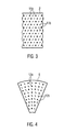
- In Figur 3 ist ein Abschnitt der Seitenwand 2 dargestellt. Ringförmige Verbindungsstellen 11a und linienförmige Verbindungsstellen 11 b verbinden die beiden Wandungen 2a und 2b. Die Verbindungsstellen 11a und 11 b sind hier in einem regelmäßigen hexagonalen Muster angeordnet. Es sind auch quadratische oder rechteckige oder sonstige regelmäßige oder unregelmäßige Muster möglich. Statt einer Kombination aus ringförmigen und linienförmigen Verbindungsstellen 11a, 11 b könnten auch nur ringförmige oder nur linienförmige Verbindungsstellen 11 a, 11 b vorgesehen sein.
- In Figur 4 ist ein Segment des Bodens 6 dargestellt. Hier sind auch ringförmige (12a) und linienförmige Verbindungslinien 12b dargestellt.
- Die linienförmigen Verbindungsstellen 11 b, 12b sind gegenüber einer Tangentialrichtung schräg angeordnet. Bei Betrieb der Maischepfanne mit einem Rührwerk strömt die Maische in der Pfanne in einem gewissen Punkt in Tangentialrichtung (Bewegungsrichtung). Die Verbindungslinien 11 b, 12b sind hier schräg zu dieser Bewegungsrichtung angeordnet, um so eine gewisse Querströmungskomponente (am Boden radial nach innen oder außen und an der Seitenwand vertikal gerichtet) induzieren zu können.
- Durch verschieden geformte Verbindungsstellen 11a, 11b, 12a, 12b können die Verbindungsstellen für verschiedene Anforderungen unabhängig voneinander optimiert werden. Zum einen haben die Verbindungsstellen 11, 12 die Funktion die beiden Wandungen zusammenzuhalten, was besonders gut durch ringförmige Verbindungsstellen 11a, 12a erreicht wird. Andererseits ermöglicht eine längliche Form (11 b, 12b) auch die Funktion des Induzierens einer Relativströmung (s.o.). Durch das gleichzeitige Vorsehen von zwei oder mehr Arten von Verbindungsstellen können beide Effekte gleichzeitig erreicht werden.
- Die Seitenwand 2 und der Boden 6 können aber auch nur mit ringförmigen oder nur mit linienförmigen Verbindungsstellen 11 oder 12 versehen sein.
- Auch können statt ringförmigen oder linienförmigen auch ovale rechteckige oder sonst wie geformte Verbindungsstellen vorgesehen sein. Durch ovale und dadurch längliche, entsprechend ausgerichtete Verbindungsstellen kann auch die gute Belastbarkeit der Verbindungen und die Funktion des Induzierens einer Querströmung mit einer Art Verbindungsstellen realisiert werden.
- In den Figuren 5 und 6 sind Detailvergrößerungen der Seitenwand 2 dargestellt, bei denen beispielhaft lediglich ringförmige Verbindungsstellen 11 vorgesehen sind. Entsprechende Formen ergeben sich jedoch in gleicher Weise für andere Verbindungsstellen. Die Seitenwand 2 ist in den Figuren 5 und 6 im Vergleich zu den Figuren 1 und 2 um 90° gedreht.
- In den Figuren 5 und 6 ist jeweils eine Seitenwand 2 mit einer Wandung 2a und einer Wandung 2b dargestellt. Die Wandung 2a ist eben, wohingegen die Wandung 2b Unebenheiten aufweist. An den Stellen 11 ist die Wandung 2b mit der Wandung 2a verbunden. Hier liegen die Wandungen 2a und 2b dicht aufeinander. Die Verbindungsstellen 11 können beispielsweise Schweißstellen sein. Diese Verbindungsstellen 11 sind bevorzugterweise ringförmig ausgebildet, um so eine gute und belastbare Verbindung zwischen den Wandungen 2a und 2b zu gewährleisten. Zwischen den Verbindungsstellen 11 sind Hohlräume 18 vorgesehen, die durch wellen-, blasen- oder wölbungsförmige Unebenheiten der Seitenwandung 2b gegeben sind. Eine Unebenheit ist in Fig. 5 mit der Bezugsziffer 20 gekennzeichnet. Die Linien in Fig. 5, die zwischen den Verbindungsstelle 11 bogenförmig laufen, dienen lediglich der Andeutung der Unebenheiten. Sie repräsentieren jedoch für sich kein tatsächliches Element der Wandung 2b.
- In Fig. 6 sind die Unebenheiten und die Hohlräume 18 aus Gründen der Anschaulichkeit etwas überhöht dargestellt.
- Wie in Figur 6 zu erkennen ist, ist die Wandstärke d2 der Wandung 2b geringer als die Wandstärke d1 der Wandung 2a. Die Wandung 2b kann beispielsweise eine Dicke d1 von 0,5 mm, 1,0 mm, 1,5 mm, 2,0 mm, 2,5 mm, 3,0 mm, 3,5 mm, 4,0 mm, 4,5 mm oder 5,0 mm bis 2,0 mm, 2,5 mm, 3,0 mm, 3,5 mm, 4,0 mm, 4,5 mm, 5,0 mm, 5,5 mm, 6,0 mm, 6,5 mm, 7,0 mm, 7,5 mm, 8,0 mm, 8,5 mm, 9,0 mm, 9,5 mm oder 10,0 mm aufweisen.
- Die Wandung 2a, kann eine Dicke d1 von 0,5 mm, 1,0 mm, 1,5 mm, 2,0 mm, 2,5 mm, 3,0 mm, 3,5 mm, 4,0 mm, 4,5 mm oder 5,0 mm bis 2,0 mm, 2,5 mm, 3,0 mm, 3,5 mm, 4,0 mm, 4,5 mm, 5,0 mm, 5,5 mm, 6,0 mm, 6,5 mm, 7,0 mm, 7,5 mm, 8,0 mm, 8,5 mm, 9,0 mm, 9,5 mm, 10,0 mm oder 10,5 mm haben.
- Ansichten entsprechend der Figuren 5 und 6 von dem Bodenelement 6, wie es in Figur 4 gezeigt ist, sind an sich recht ähnlich.
- Als Material für die Wandungen 2a, 2b kommt ein schweißbares Material, wie beispielsweise Edelstahl, in Betracht. Die Verbindungsstellen 11 sind dann Schweißstellen. Zur Herstellung der Seitenwand 2 und des Bodens 6 werden zwei Bleche mit unterschiedlichen Dicken an den Verbindungsstellen 11 oder 12 aufeinander geschweißt. Die Randbereiche der beiden Bleche werden druckdicht und vorzugsweise spaltenfrei miteinander entlang der Kanten verschweißt. Anschließend wird der Zwischenraum zwischen den beiden Blechen mit einem Druckmittel mit entsprechendem Druck beaufschlagt, sodass sich das dünnere Blech 2b auswölbt, wie dies in Figuren 2, 5 und 6 dargestellt ist. Entsprechendes gilt für die Elemente des Bodens 6.
- Sowohl Seitenwand 2 als auch Boden 6 sind vorteilhafterweise aus verschiedenen Segmenten zusammengesetzt, könnten jedoch auch aus einem einzelnen Teil bestehen. Bei gleicher Konfiguration der Verbindungsstellen 11a, 11 b sowie 12a, 12b kann Boden und Seitenwand aus demselben Rohmaterial gefertigt werden.
- In Figur 7 ist die Heizrate als Funktion der Sudnummer für zwei Fälle aufgetragen. Im ersten Fall (untere Linie) wurde eine herkömmliche Maischepfanne eingesetzt. Hier ist zu erkennen, wie mit steigender Sudnummer die Heizrate von etwa 1° Celsius pro Minute auf bis unter 0,5° Celsius pro Minute absinkt. Das Absinken der Heizrate ist im Wesentlichen dadurch bedingt, dass an der Oberfläche Maischereste festbacken, die einen Wärmeübergang verhindem (Fouling). Nach Reinigung der Maischepfanne wird die ursprüngliche Heizrate von 1° Celsius pro Minute wieder erreicht.
- Der zweite Fall zeigt das Ergebnis der Heizrate als Funktion der Sudnummer für eine Ausführungsform der vorliegenden Erfindung. Hier ist die Heizrate zum Einen wesentlich höher als im ersten Fall (höher als 2° Celsius pro Minute). Es ist jedoch weiterhin auch ersichtlich, dass kein Absinken der Heizrate als Funktion der Sudnummer zu beobachten ist. Reinigungszyklen können deshalb viel seltener durchgeführt werden oder können eventuell sogar ganz wegfallen.
Claims (14)
- Vorrichtung zum Erhitzen eines Fluids, wie etwa Maische, Würze oder Ähnliches, in der Getränketechnologie, wie etwa der Brauerei, wobei zum Erhitzen des Fluids in einem Fluidbereich (3) wenigstens eine beheizbare Kontaktfläche (2, 6) vorgesehen ist,
dadurch gekennzeichnet, dass
an der Kontaktfläche (2, 6) zumindest teilweise Unebenheiten (20) vorgesehen sind. - Vorrichtung nach Anspruch 1, dadurch gekennzeichnet, dass die Unebenheiten (20) wellenförmig und/oder blasenförmig und/oder wölbungsförmig sind.
- Vorrichtung nach einem der Ansprüche 1 oder 2, dadurch gekennzeichnet, dass die Unebenheiten (20) periodisch sind.
- Vorrichtung nach einem der Ansprüche 1 bis 3, dadurch gekennzeichnet, dass die Unebenheiten (20) an einem Boden (6) und/oder an einer Seitenwand (2) und/oder einer sonstigen mit dem Fluid in Kontakt befindlichen Fläche vorgesehen sind.
- Vorrichtung nach einem der Ansprüche 1 bis 4, dadurch gekennzeichnet, dass die Kontaktfläche (2, 6) doppelwandig ist.
- Vorrichtung nach Anspruch 5, dadurch gekennzeichnet, dass eine zum Fluidbereich (3) gerichtete Wandung (2b) dünner oder gleich dick ist, wie die andere Wandung (2a).
- Vorrichtung nach Anspruch 5 oder 6, dadurch gekennzeichnet, dass die beiden Wandungen (2a, 2b) miteinander an einer Vielzahl von Verbindungsstellen (11a, 11 b, 12a, 12b) miteinander verbunden sind, und dass die Unebenheiten (20) zwischen den Verbindungsstellen (11a, 11 b, 12a, 12b) sind.
- Vorrichtung nach Anspruch 7, dadurch gekennzeichnet, dass eine zum Fluidbereich (3) gerichtete Wandung (2b, 6b) zwischen den Verbindungsstellen (11a, 11 b, 12a, 12b) zum Fluidbereich (3) hin gewölbt ist.
- Vorrichtung nach einem der Ansprüche 7 oder 8, dadurch gekennzeichnet, dass eine von dem Fluidbereich (3) abgewandte Wandung (2a, 6a) eben ist.
- Vorrichtung nach Anspruch 9, dadurch gekennzeichnet, dass die beiden Wandungen (2a, 2b, 6a, 6b) an den Verbindungsstellen (11a, 11 b, 12a, 12b) miteinander durch Schweißungen verbunden sind.
- Vorrichtung nach einem der Ansprüche 1 bis 10, dadurch gekennzeichnet, dass eine Einrichtung (17) vorgesehen ist, durch die das Fluid entlang der Kontaktfläche (2, 6) in einer Bewegungsrichtung bewegt werden kann.
- Vorrichtung nach Anspruch 11, soweit auf Anspruch 7 zurückbezogen, dadurch gekennzeichnet, dass die Verbindungsstellen (11 b, 12b) länglich sind und mit ihrer langen Ausdehnung im Vergleich zur Bewegungsrichtung des Fluids schräg angeordnet sind.
- Vorrichtung nach einem der Ansprüche 11 oder 12, dadurch gekennzeichnet, dass die Bewegungseinrichtung ein Rührwerk und/oder eine Umpumpeinrichtung umfasst.
- Vorrichtung zum Erhitzen eines Fluids, wie etwa Maische, Würze oder Ähnliches, in der Getränketechnologie, wie etwa der Brauerei, wobei zum Erhitzen des Fluids in einem Fluidbereich (3) wenigstens eine beheizbare Kontaktfläche (2, 6) vorgesehen ist,
dadurch gekennzeichnet, dass
die Kontaktfläche (2, 6) doppelwandig ist und eine zum Fluidbereich (3) gewandte Wandung (2b, 6b) dünner oder gleich dick ist, wie eine vom Fluidbereich (3) weggewandte Wandung (2a, 6a).
Priority Applications (9)
| Application Number | Priority Date | Filing Date | Title |
|---|---|---|---|
| PL05002298T PL1688478T3 (pl) | 2005-02-03 | 2005-02-03 | Kadź zacierowa lub brzeczkowa do ogrzewania zacieru lub brzeczki |
| ES05002298T ES2330752T5 (es) | 2005-02-03 | 2005-02-03 | Caldera de maceración o de cocción para calentar cebada macerada o mosto |
| DE502005008133T DE502005008133D1 (de) | 2005-02-03 | 2005-02-03 | Maisch- oder Würzepfanne zum Erhitzen von Maische oder Würze |
| AT05002298T ATE443126T1 (de) | 2005-02-03 | 2005-02-03 | Maisch- oder würzepfanne zum erhitzen von maische oder würze |
| EP05002298.7A EP1688478B2 (de) | 2005-02-03 | 2005-02-03 | Maisch- oder Würzepfanne zum Erhitzen von Maische oder Würze |
| DK05002298.7T DK1688478T4 (da) | 2005-02-03 | 2005-02-03 | Mæske- eller urtegryde til opvarmning af mæsk eller urt |
| JP2006027434A JP4303250B2 (ja) | 2005-02-03 | 2006-02-03 | 流体加熱装置 |
| CNA2006100033299A CN1815132A (zh) | 2005-02-03 | 2006-02-05 | 用于加热流体的设备 |
| CN2012103770150A CN103017589A (zh) | 2005-02-03 | 2006-02-05 | 用于加热流体的设备 |
Applications Claiming Priority (1)
| Application Number | Priority Date | Filing Date | Title |
|---|---|---|---|
| EP05002298.7A EP1688478B2 (de) | 2005-02-03 | 2005-02-03 | Maisch- oder Würzepfanne zum Erhitzen von Maische oder Würze |
Publications (3)
| Publication Number | Publication Date |
|---|---|
| EP1688478A1 true EP1688478A1 (de) | 2006-08-09 |
| EP1688478B1 EP1688478B1 (de) | 2009-09-16 |
| EP1688478B2 EP1688478B2 (de) | 2019-06-05 |
Family
ID=34933584
Family Applications (1)
| Application Number | Title | Priority Date | Filing Date |
|---|---|---|---|
| EP05002298.7A Expired - Lifetime EP1688478B2 (de) | 2005-02-03 | 2005-02-03 | Maisch- oder Würzepfanne zum Erhitzen von Maische oder Würze |
Country Status (8)
| Country | Link |
|---|---|
| EP (1) | EP1688478B2 (de) |
| JP (1) | JP4303250B2 (de) |
| CN (2) | CN103017589A (de) |
| AT (1) | ATE443126T1 (de) |
| DE (1) | DE502005008133D1 (de) |
| DK (1) | DK1688478T4 (de) |
| ES (1) | ES2330752T5 (de) |
| PL (1) | PL1688478T3 (de) |
Cited By (6)
| Publication number | Priority date | Publication date | Assignee | Title |
|---|---|---|---|---|
| EP1743692A1 (de) | 2005-07-13 | 2007-01-17 | KRONES Aktiengesellschaft | Rührwerk |
| DE102008008150A1 (de) | 2008-02-08 | 2009-08-13 | Krones Ag | Verfahren zur Ethanolgewinnung in einer Bierbrauanlage |
| DE102008056744A1 (de) * | 2008-11-11 | 2010-05-12 | Krones Ag | Vorrichtung und Verfahren zum Strippen von Würze |
| DE102010041956A1 (de) * | 2010-10-04 | 2012-04-05 | Krones Aktiengesellschaft | Verfahren und Vorrichtung insbesondere zum Maischen bei der Herstellung von Bier |
| DE202014105416U1 (de) * | 2014-11-11 | 2016-02-12 | Krones Ag | Vorrichtung zum Würzekochen |
| US10408861B2 (en) | 2015-03-04 | 2019-09-10 | Rohde & Schwarz Gmbh & Co. Kg | Circuit for compensating an offset voltage in an amplifier |
Families Citing this family (7)
| Publication number | Priority date | Publication date | Assignee | Title |
|---|---|---|---|---|
| DE102009055300A1 (de) * | 2009-12-23 | 2011-06-30 | Krones Ag, 93073 | Vorrichtung und Verfahren zum Rückgewinnen von Energie |
| DE202010018139U1 (de) * | 2010-10-04 | 2014-04-10 | Krones Ag | Vorrichtung zum Maischen bei der Herstellung von Bier |
| JP6105922B2 (ja) * | 2012-12-26 | 2017-03-29 | アサヒビール株式会社 | 非発酵ビールテイスト飲料及びその製造方法 |
| KR101549062B1 (ko) | 2015-04-03 | 2015-09-02 | 임윤환 | 맥즙 제조장치 |
| KR101661095B1 (ko) * | 2016-03-31 | 2016-09-29 | 임윤환 | 맥즙 제조장치 |
| JP6545208B2 (ja) * | 2017-03-03 | 2019-07-17 | アサヒビール株式会社 | 非発酵ビールテイスト飲料及びその製造方法 |
| JP2019107023A (ja) * | 2019-03-05 | 2019-07-04 | アサヒビール株式会社 | 非発酵ビールテイスト飲料及びその製造方法 |
Citations (5)
| Publication number | Priority date | Publication date | Assignee | Title |
|---|---|---|---|---|
| DE686020C (de) | 1935-09-06 | 1940-01-02 | Jacob Carl Maschinenfabrik | Feuerbeheizte Braupfanne |
| US4163417A (en) | 1976-07-23 | 1979-08-07 | Anton Steinecker Maschinenfabrik Gmbh | Mash and wort tub |
| DE19828686C1 (de) * | 1998-06-26 | 1999-08-26 | Steinecker Maschf Anton | Gefäß zur Behandlung von Würze bei der Bierherstellung |
| WO2001012773A2 (de) * | 1999-08-16 | 2001-02-22 | Beer-Lilly Brauereianlagen Handelsges.M.B.H. | Würzepfanne |
| WO2002012433A1 (de) | 2000-08-08 | 2002-02-14 | Anton Steinecker Maschinenfabrik Gmbh | Gefäss für die bierhestellung |
Family Cites Families (5)
| Publication number | Priority date | Publication date | Assignee | Title |
|---|---|---|---|---|
| US3384163A (en) * | 1966-09-23 | 1968-05-21 | Schlitz Brewing Co J | Heating unit for a brew kettle |
| US3910172A (en) * | 1973-01-18 | 1975-10-07 | Kronenbourg Brasseries | Tanks |
| GB1453614A (en) * | 1973-05-30 | 1976-10-27 | Widnes Foundry Eng Co Ltd | Process vessels |
| CN2133584Y (zh) * | 1992-08-25 | 1993-05-19 | 浙江大学 | 制药工业用发酵罐 |
| ES1033236Y (es) * | 1996-02-13 | 1997-01-16 | Magallon Ismael Perez | Deposito perfeccionado, para productores-acumuladores de agua caliente sanitaria. |
-
2005
- 2005-02-03 AT AT05002298T patent/ATE443126T1/de active
- 2005-02-03 DE DE502005008133T patent/DE502005008133D1/de not_active Expired - Lifetime
- 2005-02-03 PL PL05002298T patent/PL1688478T3/pl unknown
- 2005-02-03 EP EP05002298.7A patent/EP1688478B2/de not_active Expired - Lifetime
- 2005-02-03 DK DK05002298.7T patent/DK1688478T4/da active
- 2005-02-03 ES ES05002298T patent/ES2330752T5/es not_active Expired - Lifetime
-
2006
- 2006-02-03 JP JP2006027434A patent/JP4303250B2/ja not_active Expired - Fee Related
- 2006-02-05 CN CN2012103770150A patent/CN103017589A/zh active Pending
- 2006-02-05 CN CNA2006100033299A patent/CN1815132A/zh active Pending
Patent Citations (5)
| Publication number | Priority date | Publication date | Assignee | Title |
|---|---|---|---|---|
| DE686020C (de) | 1935-09-06 | 1940-01-02 | Jacob Carl Maschinenfabrik | Feuerbeheizte Braupfanne |
| US4163417A (en) | 1976-07-23 | 1979-08-07 | Anton Steinecker Maschinenfabrik Gmbh | Mash and wort tub |
| DE19828686C1 (de) * | 1998-06-26 | 1999-08-26 | Steinecker Maschf Anton | Gefäß zur Behandlung von Würze bei der Bierherstellung |
| WO2001012773A2 (de) * | 1999-08-16 | 2001-02-22 | Beer-Lilly Brauereianlagen Handelsges.M.B.H. | Würzepfanne |
| WO2002012433A1 (de) | 2000-08-08 | 2002-02-14 | Anton Steinecker Maschinenfabrik Gmbh | Gefäss für die bierhestellung |
Cited By (7)
| Publication number | Priority date | Publication date | Assignee | Title |
|---|---|---|---|---|
| EP1743692A1 (de) | 2005-07-13 | 2007-01-17 | KRONES Aktiengesellschaft | Rührwerk |
| DE102008008150A1 (de) | 2008-02-08 | 2009-08-13 | Krones Ag | Verfahren zur Ethanolgewinnung in einer Bierbrauanlage |
| DE102008056744A1 (de) * | 2008-11-11 | 2010-05-12 | Krones Ag | Vorrichtung und Verfahren zum Strippen von Würze |
| WO2010054755A3 (de) * | 2008-11-11 | 2011-02-24 | Krones Ag | Vorrichtung und verfahren zum strippen von würze |
| DE102010041956A1 (de) * | 2010-10-04 | 2012-04-05 | Krones Aktiengesellschaft | Verfahren und Vorrichtung insbesondere zum Maischen bei der Herstellung von Bier |
| DE202014105416U1 (de) * | 2014-11-11 | 2016-02-12 | Krones Ag | Vorrichtung zum Würzekochen |
| US10408861B2 (en) | 2015-03-04 | 2019-09-10 | Rohde & Schwarz Gmbh & Co. Kg | Circuit for compensating an offset voltage in an amplifier |
Also Published As
| Publication number | Publication date |
|---|---|
| ES2330752T5 (es) | 2020-04-16 |
| JP4303250B2 (ja) | 2009-07-29 |
| PL1688478T3 (pl) | 2010-02-26 |
| CN103017589A (zh) | 2013-04-03 |
| ES2330752T3 (es) | 2009-12-15 |
| DE502005008133D1 (de) | 2009-10-29 |
| ATE443126T1 (de) | 2009-10-15 |
| EP1688478B2 (de) | 2019-06-05 |
| EP1688478B1 (de) | 2009-09-16 |
| DK1688478T4 (da) | 2019-08-26 |
| DK1688478T3 (da) | 2009-12-07 |
| JP2006246884A (ja) | 2006-09-21 |
| CN1815132A (zh) | 2006-08-09 |
Similar Documents
| Publication | Publication Date | Title |
|---|---|---|
| EP1688478B1 (de) | Maisch- oder Würzepfanne zum Erhitzen von Maische oder Würze | |
| DE2010675A1 (de) | Haushaltsmaschine zur Herstellung von Auszügen aus Kaffee, Tee usw | |
| EP3513696B1 (de) | Küchenmaschine mit einem abdeckelement für ein zubereitunsgefäss | |
| DE10128287A1 (de) | Kocher | |
| DE2245442A1 (de) | Vorrichtung zur unterstuetzung der entstehung von turbulenz | |
| EP2220207B1 (de) | Vorrichtung und verfahren zum kontinuierlichen würzekochen | |
| EP2625259B1 (de) | Verfahren und vorrichtung insbesondere zum maischen bei der herstellung von bier | |
| EP1475001B1 (de) | Verfahren zur Herstellung einer Vielzahl von Portionen einer vorgekochten Speise | |
| AT6980U1 (de) | Waffelblatt | |
| EP2388066B1 (de) | Vorrichtung und Verfahren zum Zugeben von Hopfen | |
| CH657069A5 (de) | Heiz- und kuehlbarer scheibenruehrer. | |
| DE69310850T2 (de) | Verpackungsmaschine | |
| WO2002016016A1 (de) | Vorrichtung und verfahren zum mischen von komponenten | |
| EP2624945B1 (de) | Vorrichtung und verfahren zum erwärmen eines flüssigen mediums, insbesondere maischvorrichtung zum herstellen von bier | |
| WO2019048471A1 (de) | Vorrichtung und verfahren zum maischen und filtrieren für die bierherstellung | |
| EP1743692B1 (de) | Rührwerk sowie dessen Verwendung | |
| WO2010031193A1 (de) | Installation zur entnahme von wärme aus fliessendem wasser | |
| DE69722826T2 (de) | Kreisförmiges trocknungselement und diesen enthaltende trocknungsvorrichtung | |
| DE19530806C2 (de) | Sterilisiergerät und Gerät zum Herstellen eines Flüssigproduktes | |
| AT407246B (de) | Verfahren zur erwärmung von dünnschlamm und anordnung zur durchführung des verfahrens | |
| WO2004101140A1 (de) | Verfahren und reaktor zur kontinuierlichen herstellung von polymeren | |
| EP2412286A2 (de) | Wasserführendes Haushaltsgerät, insbesondere Geschirrspülmaschine | |
| EP0042037B1 (de) | Maischpfanne | |
| DE4135560C2 (de) | ||
| EP2625260B1 (de) | Verfahren und vorrichtung insbesondere zum maischen bei der herstellung von bier |
Legal Events
| Date | Code | Title | Description |
|---|---|---|---|
| PUAI | Public reference made under article 153(3) epc to a published international application that has entered the european phase |
Free format text: ORIGINAL CODE: 0009012 |
|
| AK | Designated contracting states |
Kind code of ref document: A1 Designated state(s): AT BE BG CH CY CZ DE DK EE ES FI FR GB GR HU IE IS IT LI LT LU MC NL PL PT RO SE SI SK TR |
|
| AX | Request for extension of the european patent |
Extension state: AL BA HR LV MK YU |
|
| 17P | Request for examination filed |
Effective date: 20070201 |
|
| AKX | Designation fees paid |
Designated state(s): AT BE BG CH CY CZ DE DK EE ES FI FR GB GR HU IE IS IT LI LT LU MC NL PL PT RO SE SI SK TR |
|
| 17Q | First examination report despatched |
Effective date: 20080814 |
|
| GRAP | Despatch of communication of intention to grant a patent |
Free format text: ORIGINAL CODE: EPIDOSNIGR1 |
|
| RTI1 | Title (correction) |
Free format text: MASH OR WORT PAN FOR HEATING MASH OR WORT |
|
| GRAS | Grant fee paid |
Free format text: ORIGINAL CODE: EPIDOSNIGR3 |
|
| GRAA | (expected) grant |
Free format text: ORIGINAL CODE: 0009210 |
|
| AK | Designated contracting states |
Kind code of ref document: B1 Designated state(s): AT BE BG CH CY CZ DE DK EE ES FI FR GB GR HU IE IS IT LI LT LU MC NL PL PT RO SE SI SK TR |
|
| REG | Reference to a national code |
Ref country code: GB Ref legal event code: FG4D Free format text: NOT ENGLISH |
|
| REG | Reference to a national code |
Ref country code: CH Ref legal event code: EP Ref country code: CH Ref legal event code: NV Representative=s name: BOVARD AG PATENTANWAELTE |
|
| REG | Reference to a national code |
Ref country code: IE Ref legal event code: FG4D |
|
| REG | Reference to a national code |
Ref country code: SE Ref legal event code: TRGR |
|
| REF | Corresponds to: |
Ref document number: 502005008133 Country of ref document: DE Date of ref document: 20091029 Kind code of ref document: P |
|
| REG | Reference to a national code |
Ref country code: RO Ref legal event code: EPE |
|
| REG | Reference to a national code |
Ref country code: DK Ref legal event code: T3 |
|
| REG | Reference to a national code |
Ref country code: ES Ref legal event code: FG2A Ref document number: 2330752 Country of ref document: ES Kind code of ref document: T3 |
|
| PLBI | Opposition filed |
Free format text: ORIGINAL CODE: 0009260 |
|
| PG25 | Lapsed in a contracting state [announced via postgrant information from national office to epo] |
Ref country code: LT Free format text: LAPSE BECAUSE OF FAILURE TO SUBMIT A TRANSLATION OF THE DESCRIPTION OR TO PAY THE FEE WITHIN THE PRESCRIBED TIME-LIMIT Effective date: 20090916 |
|
| 26 | Opposition filed |
Opponent name: GEA BREWERY SYSTEMS GMBH Effective date: 20091223 |
|
| LTIE | Lt: invalidation of european patent or patent extension |
Effective date: 20090916 |
|
| PG25 | Lapsed in a contracting state [announced via postgrant information from national office to epo] |
Ref country code: SI Free format text: LAPSE BECAUSE OF FAILURE TO SUBMIT A TRANSLATION OF THE DESCRIPTION OR TO PAY THE FEE WITHIN THE PRESCRIBED TIME-LIMIT Effective date: 20090916 |
|
| REG | Reference to a national code |
Ref country code: PL Ref legal event code: T3 |
|
| PG25 | Lapsed in a contracting state [announced via postgrant information from national office to epo] |
Ref country code: CY Free format text: LAPSE BECAUSE OF FAILURE TO SUBMIT A TRANSLATION OF THE DESCRIPTION OR TO PAY THE FEE WITHIN THE PRESCRIBED TIME-LIMIT Effective date: 20090916 |
|
| NLR1 | Nl: opposition has been filed with the epo |
Opponent name: GEA BREWERY SYSTEMS GMBH |
|
| PG25 | Lapsed in a contracting state [announced via postgrant information from national office to epo] |
Ref country code: IS Free format text: LAPSE BECAUSE OF FAILURE TO SUBMIT A TRANSLATION OF THE DESCRIPTION OR TO PAY THE FEE WITHIN THE PRESCRIBED TIME-LIMIT Effective date: 20100116 Ref country code: PT Free format text: LAPSE BECAUSE OF FAILURE TO SUBMIT A TRANSLATION OF THE DESCRIPTION OR TO PAY THE FEE WITHIN THE PRESCRIBED TIME-LIMIT Effective date: 20100118 Ref country code: EE Free format text: LAPSE BECAUSE OF FAILURE TO SUBMIT A TRANSLATION OF THE DESCRIPTION OR TO PAY THE FEE WITHIN THE PRESCRIBED TIME-LIMIT Effective date: 20090916 |
|
| PG25 | Lapsed in a contracting state [announced via postgrant information from national office to epo] |
Ref country code: SK Free format text: LAPSE BECAUSE OF FAILURE TO SUBMIT A TRANSLATION OF THE DESCRIPTION OR TO PAY THE FEE WITHIN THE PRESCRIBED TIME-LIMIT Effective date: 20090916 |
|
| PLBI | Opposition filed |
Free format text: ORIGINAL CODE: 0009260 |
|
| REG | Reference to a national code |
Ref country code: HU Ref legal event code: AG4A Ref document number: E007361 Country of ref document: HU |
|
| PLAX | Notice of opposition and request to file observation + time limit sent |
Free format text: ORIGINAL CODE: EPIDOSNOBS2 |
|
| 26 | Opposition filed |
Opponent name: ZIEMANN LUDWIGSBURG GMBH Effective date: 20100615 Opponent name: GEA BREWERY SYSTEMS GMBH Effective date: 20091223 |
|
| PG25 | Lapsed in a contracting state [announced via postgrant information from national office to epo] |
Ref country code: MC Free format text: LAPSE BECAUSE OF NON-PAYMENT OF DUE FEES Effective date: 20100301 Ref country code: GR Free format text: LAPSE BECAUSE OF FAILURE TO SUBMIT A TRANSLATION OF THE DESCRIPTION OR TO PAY THE FEE WITHIN THE PRESCRIBED TIME-LIMIT Effective date: 20091217 |
|
| PLAF | Information modified related to communication of a notice of opposition and request to file observations + time limit |
Free format text: ORIGINAL CODE: EPIDOSCOBS2 |
|
| PLAF | Information modified related to communication of a notice of opposition and request to file observations + time limit |
Free format text: ORIGINAL CODE: EPIDOSCOBS2 |
|
| PLBB | Reply of patent proprietor to notice(s) of opposition received |
Free format text: ORIGINAL CODE: EPIDOSNOBS3 |
|
| REG | Reference to a national code |
Ref country code: CH Ref legal event code: PFA Owner name: KRONES AKTIENGESELLSCHAFT Free format text: KRONES AKTIENGESELLSCHAFT#BOEHMERWALDSTRASSE 5#93073 NEUTRAUBLING (DE) -TRANSFER TO- KRONES AKTIENGESELLSCHAFT#BOEHMERWALDSTRASSE 5#93073 NEUTRAUBLING (DE) |
|
| PG25 | Lapsed in a contracting state [announced via postgrant information from national office to epo] |
Ref country code: LU Free format text: LAPSE BECAUSE OF NON-PAYMENT OF DUE FEES Effective date: 20100203 |
|
| PG25 | Lapsed in a contracting state [announced via postgrant information from national office to epo] |
Ref country code: TR Free format text: LAPSE BECAUSE OF FAILURE TO SUBMIT A TRANSLATION OF THE DESCRIPTION OR TO PAY THE FEE WITHIN THE PRESCRIBED TIME-LIMIT Effective date: 20090916 |
|
| PLCK | Communication despatched that opposition was rejected |
Free format text: ORIGINAL CODE: EPIDOSNREJ1 |
|
| PLAO | Information deleted related to despatch of communication that opposition is rejected |
Free format text: ORIGINAL CODE: EPIDOSDREJ1 |
|
| PLAB | Opposition data, opponent's data or that of the opponent's representative modified |
Free format text: ORIGINAL CODE: 0009299OPPO |
|
| APBM | Appeal reference recorded |
Free format text: ORIGINAL CODE: EPIDOSNREFNO |
|
| APBP | Date of receipt of notice of appeal recorded |
Free format text: ORIGINAL CODE: EPIDOSNNOA2O |
|
| APAH | Appeal reference modified |
Free format text: ORIGINAL CODE: EPIDOSCREFNO |
|
| PLAB | Opposition data, opponent's data or that of the opponent's representative modified |
Free format text: ORIGINAL CODE: 0009299OPPO |
|
| R26 | Opposition filed (corrected) |
Opponent name: ZIEMANN LUDWIGSBURG GMBH Effective date: 20100615 |
|
| R26 | Opposition filed (corrected) |
Opponent name: ZIEMANN LUDWIGSBURG GMBH Effective date: 20100615 |
|
| APBQ | Date of receipt of statement of grounds of appeal recorded |
Free format text: ORIGINAL CODE: EPIDOSNNOA3O |
|
| REG | Reference to a national code |
Ref country code: FR Ref legal event code: PLFP Year of fee payment: 11 |
|
| PGFP | Annual fee paid to national office [announced via postgrant information from national office to epo] |
Ref country code: CH Payment date: 20150213 Year of fee payment: 11 Ref country code: IE Payment date: 20150210 Year of fee payment: 11 Ref country code: FI Payment date: 20150209 Year of fee payment: 11 Ref country code: RO Payment date: 20150114 Year of fee payment: 11 Ref country code: HU Payment date: 20150114 Year of fee payment: 11 Ref country code: BG Payment date: 20150119 Year of fee payment: 11 |
|
| PGFP | Annual fee paid to national office [announced via postgrant information from national office to epo] |
Ref country code: SE Payment date: 20150212 Year of fee payment: 11 Ref country code: AT Payment date: 20150126 Year of fee payment: 11 Ref country code: PL Payment date: 20150114 Year of fee payment: 11 |
|
| PLAB | Opposition data, opponent's data or that of the opponent's representative modified |
Free format text: ORIGINAL CODE: 0009299OPPO |
|
| R26 | Opposition filed (corrected) |
Opponent name: RA DR. TIBOR BRAUN, INSOLVENZVERWALTER UEBER DAS V Effective date: 20100615 |
|
| REG | Reference to a national code |
Ref country code: FR Ref legal event code: PLFP Year of fee payment: 12 |
|
| REG | Reference to a national code |
Ref country code: CH Ref legal event code: PL |
|
| REG | Reference to a national code |
Ref country code: SE Ref legal event code: EUG |
|
| REG | Reference to a national code |
Ref country code: AT Ref legal event code: MM01 Ref document number: 443126 Country of ref document: AT Kind code of ref document: T Effective date: 20160203 |
|
| PG25 | Lapsed in a contracting state [announced via postgrant information from national office to epo] |
Ref country code: LI Free format text: LAPSE BECAUSE OF NON-PAYMENT OF DUE FEES Effective date: 20160229 Ref country code: FI Free format text: LAPSE BECAUSE OF NON-PAYMENT OF DUE FEES Effective date: 20160203 Ref country code: CH Free format text: LAPSE BECAUSE OF NON-PAYMENT OF DUE FEES Effective date: 20160229 Ref country code: HU Free format text: LAPSE BECAUSE OF NON-PAYMENT OF DUE FEES Effective date: 20160204 |
|
| PG25 | Lapsed in a contracting state [announced via postgrant information from national office to epo] |
Ref country code: RO Free format text: LAPSE BECAUSE OF NON-PAYMENT OF DUE FEES Effective date: 20160203 Ref country code: AT Free format text: LAPSE BECAUSE OF NON-PAYMENT OF DUE FEES Effective date: 20160203 Ref country code: SE Free format text: LAPSE BECAUSE OF NON-PAYMENT OF DUE FEES Effective date: 20160204 |
|
| REG | Reference to a national code |
Ref country code: IE Ref legal event code: MM4A |
|
| REG | Reference to a national code |
Ref country code: FR Ref legal event code: PLFP Year of fee payment: 13 |
|
| PG25 | Lapsed in a contracting state [announced via postgrant information from national office to epo] |
Ref country code: IE Free format text: LAPSE BECAUSE OF NON-PAYMENT OF DUE FEES Effective date: 20160203 |
|
| APAH | Appeal reference modified |
Free format text: ORIGINAL CODE: EPIDOSCREFNO |
|
| PG25 | Lapsed in a contracting state [announced via postgrant information from national office to epo] |
Ref country code: PL Free format text: LAPSE BECAUSE OF NON-PAYMENT OF DUE FEES Effective date: 20160203 |
|
| REG | Reference to a national code |
Ref country code: FR Ref legal event code: PLFP Year of fee payment: 14 |
|
| APAH | Appeal reference modified |
Free format text: ORIGINAL CODE: EPIDOSCREFNO |
|
| APBU | Appeal procedure closed |
Free format text: ORIGINAL CODE: EPIDOSNNOA9O |
|
| PG25 | Lapsed in a contracting state [announced via postgrant information from national office to epo] |
Ref country code: BG Free format text: LAPSE BECAUSE OF NON-PAYMENT OF DUE FEES Effective date: 20170808 |
|
| PUAH | Patent maintained in amended form |
Free format text: ORIGINAL CODE: 0009272 |
|
| STAA | Information on the status of an ep patent application or granted ep patent |
Free format text: STATUS: PATENT MAINTAINED AS AMENDED |
|
| 27A | Patent maintained in amended form |
Effective date: 20190605 |
|
| AK | Designated contracting states |
Kind code of ref document: B2 Designated state(s): AT BE BG CH CY CZ DE DK EE ES FI FR GB GR HU IE IS IT LI LT LU MC NL PL PT RO SE SI SK TR |
|
| REG | Reference to a national code |
Ref country code: DE Ref legal event code: R102 Ref document number: 502005008133 Country of ref document: DE |
|
| REG | Reference to a national code |
Ref country code: NL Ref legal event code: FP |
|
| REG | Reference to a national code |
Ref country code: DK Ref legal event code: T4 Effective date: 20190822 |
|
| REG | Reference to a national code |
Ref country code: ES Ref legal event code: DC2A Ref document number: 2330752 Country of ref document: ES Kind code of ref document: T5 Effective date: 20200416 |
|
| PGFP | Annual fee paid to national office [announced via postgrant information from national office to epo] |
Ref country code: CZ Payment date: 20200123 Year of fee payment: 16 |
|
| PGFP | Annual fee paid to national office [announced via postgrant information from national office to epo] |
Ref country code: FR Payment date: 20200113 Year of fee payment: 16 |
|
| PGFP | Annual fee paid to national office [announced via postgrant information from national office to epo] |
Ref country code: IT Payment date: 20210112 Year of fee payment: 17 |
|
| PG25 | Lapsed in a contracting state [announced via postgrant information from national office to epo] |
Ref country code: CZ Free format text: LAPSE BECAUSE OF NON-PAYMENT OF DUE FEES Effective date: 20210203 |
|
| PG25 | Lapsed in a contracting state [announced via postgrant information from national office to epo] |
Ref country code: FR Free format text: LAPSE BECAUSE OF NON-PAYMENT OF DUE FEES Effective date: 20210228 |
|
| PG25 | Lapsed in a contracting state [announced via postgrant information from national office to epo] |
Ref country code: IT Free format text: LAPSE BECAUSE OF NON-PAYMENT OF DUE FEES Effective date: 20220203 |
|
| P01 | Opt-out of the competence of the unified patent court (upc) registered |
Effective date: 20230523 |
|
| PGFP | Annual fee paid to national office [announced via postgrant information from national office to epo] |
Ref country code: NL Payment date: 20240108 Year of fee payment: 20 |
|
| PGFP | Annual fee paid to national office [announced via postgrant information from national office to epo] |
Ref country code: ES Payment date: 20240305 Year of fee payment: 20 |
|
| PGFP | Annual fee paid to national office [announced via postgrant information from national office to epo] |
Ref country code: DE Payment date: 20231229 Year of fee payment: 20 Ref country code: GB Payment date: 20240108 Year of fee payment: 20 |
|
| PGFP | Annual fee paid to national office [announced via postgrant information from national office to epo] |
Ref country code: DK Payment date: 20240214 Year of fee payment: 20 Ref country code: BE Payment date: 20240105 Year of fee payment: 20 |
|
| REG | Reference to a national code |
Ref country code: DE Ref legal event code: R071 Ref document number: 502005008133 Country of ref document: DE |
|
| REG | Reference to a national code |
Ref country code: NL Ref legal event code: MK Effective date: 20250202 |
|
| REG | Reference to a national code |
Ref country code: DK Ref legal event code: EUP Expiry date: 20250203 |
|
| REG | Reference to a national code |
Ref country code: GB Ref legal event code: PE20 Expiry date: 20250202 |
|
| PG25 | Lapsed in a contracting state [announced via postgrant information from national office to epo] |
Ref country code: GB Free format text: LAPSE BECAUSE OF EXPIRATION OF PROTECTION Effective date: 20250202 |
|
| REG | Reference to a national code |
Ref country code: BE Ref legal event code: MK Effective date: 20250203 |
|
| REG | Reference to a national code |
Ref country code: ES Ref legal event code: FD2A Effective date: 20250530 |
|
| PG25 | Lapsed in a contracting state [announced via postgrant information from national office to epo] |
Ref country code: ES Free format text: LAPSE BECAUSE OF EXPIRATION OF PROTECTION Effective date: 20250204 |