EP1688024B1 - Steuer-anordnung - Google Patents
Steuer-anordnung Download PDFInfo
- Publication number
- EP1688024B1 EP1688024B1 EP04768668A EP04768668A EP1688024B1 EP 1688024 B1 EP1688024 B1 EP 1688024B1 EP 04768668 A EP04768668 A EP 04768668A EP 04768668 A EP04768668 A EP 04768668A EP 1688024 B1 EP1688024 B1 EP 1688024B1
- Authority
- EP
- European Patent Office
- Prior art keywords
- controller
- control arrangement
- arrangement according
- heat exchanger
- control
- Prior art date
- Legal status (The legal status is an assumption and is not a legal conclusion. Google has not performed a legal analysis and makes no representation as to the accuracy of the status listed.)
- Expired - Lifetime
Links
- 239000012530 fluid Substances 0.000 claims description 30
- 239000003570 air Substances 0.000 claims description 25
- 230000000694 effects Effects 0.000 claims description 19
- 239000000446 fuel Substances 0.000 claims description 19
- 239000012080 ambient air Substances 0.000 claims description 5
- 230000001419 dependent effect Effects 0.000 claims description 5
- 238000004804 winding Methods 0.000 description 9
- 238000001816 cooling Methods 0.000 description 6
- 230000001052 transient effect Effects 0.000 description 5
- 238000010586 diagram Methods 0.000 description 3
- XUIMIQQOPSSXEZ-UHFFFAOYSA-N Silicon Chemical compound [Si] XUIMIQQOPSSXEZ-UHFFFAOYSA-N 0.000 description 1
- 238000009529 body temperature measurement Methods 0.000 description 1
- 238000005094 computer simulation Methods 0.000 description 1
- 239000012809 cooling fluid Substances 0.000 description 1
- 230000007613 environmental effect Effects 0.000 description 1
- 238000012986 modification Methods 0.000 description 1
- 230000004048 modification Effects 0.000 description 1
- 238000013021 overheating Methods 0.000 description 1
- 229910052710 silicon Inorganic materials 0.000 description 1
- 239000010703 silicon Substances 0.000 description 1
Images


Classifications
-
- F—MECHANICAL ENGINEERING; LIGHTING; HEATING; WEAPONS; BLASTING
- F02—COMBUSTION ENGINES; HOT-GAS OR COMBUSTION-PRODUCT ENGINE PLANTS
- F02C—GAS-TURBINE PLANTS; AIR INTAKES FOR JET-PROPULSION PLANTS; CONTROLLING FUEL SUPPLY IN AIR-BREATHING JET-PROPULSION PLANTS
- F02C7/00—Features, components parts, details or accessories, not provided for in, or of interest apart form groups F02C1/00 - F02C6/00; Air intakes for jet-propulsion plants
- F02C7/12—Cooling of plants
- F02C7/16—Cooling of plants characterised by cooling medium
- F02C7/18—Cooling of plants characterised by cooling medium the medium being gaseous, e.g. air
-
- F—MECHANICAL ENGINEERING; LIGHTING; HEATING; WEAPONS; BLASTING
- F01—MACHINES OR ENGINES IN GENERAL; ENGINE PLANTS IN GENERAL; STEAM ENGINES
- F01D—NON-POSITIVE DISPLACEMENT MACHINES OR ENGINES, e.g. STEAM TURBINES
- F01D25/00—Component parts, details, or accessories, not provided for in, or of interest apart from, other groups
- F01D25/08—Cooling; Heating; Heat-insulation
- F01D25/12—Cooling
-
- F—MECHANICAL ENGINEERING; LIGHTING; HEATING; WEAPONS; BLASTING
- F02—COMBUSTION ENGINES; HOT-GAS OR COMBUSTION-PRODUCT ENGINE PLANTS
- F02C—GAS-TURBINE PLANTS; AIR INTAKES FOR JET-PROPULSION PLANTS; CONTROLLING FUEL SUPPLY IN AIR-BREATHING JET-PROPULSION PLANTS
- F02C7/00—Features, components parts, details or accessories, not provided for in, or of interest apart form groups F02C1/00 - F02C6/00; Air intakes for jet-propulsion plants
- F02C7/12—Cooling of plants
-
- Y—GENERAL TAGGING OF NEW TECHNOLOGICAL DEVELOPMENTS; GENERAL TAGGING OF CROSS-SECTIONAL TECHNOLOGIES SPANNING OVER SEVERAL SECTIONS OF THE IPC; TECHNICAL SUBJECTS COVERED BY FORMER USPC CROSS-REFERENCE ART COLLECTIONS [XRACs] AND DIGESTS
- Y02—TECHNOLOGIES OR APPLICATIONS FOR MITIGATION OR ADAPTATION AGAINST CLIMATE CHANGE
- Y02T—CLIMATE CHANGE MITIGATION TECHNOLOGIES RELATED TO TRANSPORTATION
- Y02T50/00—Aeronautics or air transport
- Y02T50/60—Efficient propulsion technologies, e.g. for aircraft
Definitions
- This invention relates to control arrangements. More particularly, but not exclusively, the invention relates to control arrangements in which power electronic components are cooled, for example on engines such as gas turbine engines see for example EP-A-1 113 233 .
- cooling is achieved by attaching the components to heat sinks.
- the heat sinks are supplied with a fluid, such as fuel or air, which acts as the low temperature reservoir to absorb the heat.
- a problem with this arrangement is that in some conditions of use of the engine, the temperature difference between the fluid and the component to be cooled is not large enough to effect sufficient cooling of the component.
- a control arrangement for controlling an action having controller means for the action, the arrangement characterised in that there is a first selectable controller for controlling the action, a second selectable controller for controlling the same action as the first selectable controller, a selector for selecting one of the first controller and/or the second controller to control said action, the arrangement having a first heat exchanger associated with the first controller to effect a transfer of heat between the first controller and the first heat exchanger dependent upon a first flow, and a second heat exchanger associated with the second controller to effect a transfer of heat between the second controller and the second heat exchanger dependent upon a second flow, the selector capable of determining the availability of the first flow and/or the second flow and accordingly select the first controller or the second controller to control the action.
- the selector is provided to select one or the other of the first and second controllers to control said action depending upon the condition of the control arrangement.
- the selector is provided to select the first controller to control said action in a first condition of the arrangement, and to select the second controller to control said action in a second condition of the arrangement.
- the first heat exchanger is arranged to effect said heat transfer when the first controller is selected.
- the second heat exchanger is arranged to effect said heat transfer when the second controller is selected.
- the first heat exchanger may be arranged to cool the first controller.
- the second heat exchanger may be arranged to cool the second controller.
- the first controller may comprise electronic components, which may be power electronic components.
- the electronic components of the first controller comprise at least one transistor and may also comprise at least one diode.
- the, or each, transistor of the first controller is an insulated gate bipolar transistor.
- the second controller may comprise electronic components, which may be power electronic components.
- the electronic components of the second controller comprise at least one transistor and may also comprise at least one diode.
- the, or each, transistor of the second controller is an insulated gate bipolar transistor.
- the first and second controllers may be identical to each other.
- the first heat exchanger may comprise a fluid, preferably a flow of the fluid to effect said transfer of heat.
- the fluid may comprise fuel or air.
- the second heat exchanger comprises a second fluid, preferably a flow of the second fluid to effect said heat transfer.
- the second fluid comprises fuel or air.
- the first fluid associated with the first heat exchanger may be fuel
- the second fluid for the second heat exchanger may be air
- the air may be a flow of air from the fan.
- control arrangement may comprise a selectable third controller for controlling the action, which can be selected by the selector, and a third heat exchanger to effect transfer of heat between the third controller means and the third heat exchanger.
- the third controller may comprise electronic components, which may be power electronic components.
- the electronic components of the third controller comprise at least one transistor and may also comprise at least one diode.
- the, or each, transistor of the third controller is an insulated gate bipolar transistor.
- the third heat exchanger may comprise a third fluid, preferably a flow of the third fluid to effect said transfer of heat.
- the third fluid may comprise fuel or air.
- the third heat exchanger means may be arranged to cool the third controller.
- the third fluid may be a flow of ambient air from a region external of the engine.
- the third controller may be identical to the first and second controller.
- the third heat exchange means is preferably arranged to effect said heat transfer when the third controller is selected.
- control arrangement may comprise any desired number of selectable further controller and associated heat exchangers.
- the further controller may comprise the features of the first and second controllers as described above, and the further heat exchanger may comprise features of the first and second heat exchanger as described above.
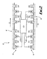
- a control arrangement 10 comprising a first controller 12 for controlling an action, and a second controller 14 also for controlling the aforesaid action.
- a selector 22 is also provided for selecting either the first controller 12 or the second controller 14 to control the action.
- the selector 22 is omitted from Figs. 1 and 3 for clarity but is shown in Fig. 2.
- the control arrangement 10 further includes a first heat exchanger 16 associated with the first controller 12, and a second heat exchanger 18 associated with the second controller 14.
- the first and second heat exchangers 16, 18 are provided to cool the respective first and second controllers 12, 14.
- the first and second controllers 12, 14 are connected between a positive bus bar 15A and a negative bus bar 15B.
- Each of the first and second controllers 12, 14 comprises a plurality of power electronic components in the form of transistors designated with the letter T, and diodes designated with the letter D. Both controllers 12, 14 are provided to direct the electrical power through a machine winding 20.
- the first heat exchanger 16 is in the form of a heat sink supplied with a fluid, which, in the case of the embodiment shown is in the form of a flow of fuel F1 from an engine.
- the second heat exchanger 18 is supplied with a second fluid, and in the case of the second heat exchanger 18 in the embodiment shown, the fluid is in the form of a flow of air F2, which may be from a fan, or may be ambient air from outside the engine, dependent upon different conditions during the flight cycle of the engine.
- the electronic components forming part of the first and second controllers 12, 14 may serve to control supply of power from the aircraft to the engine to start the engine and from the engine to the aircraft for operation of aircraft control surfaces and landing gear and/or may power a compressor providing compressed air for environmental control within the aircraft.
- power electronic devices such as insulated gate bipolar transistors or other devices which are silicon based will be employed in this electronic circuitry which requires to be maintained below a predetermined temperature, generally around 125°C, for effective operation and long life.
- the fan air will be at a relatively high temperature. This will inhibit the cooling of the second controllers 14.
- the fuel flow rate is high and the fuel is therefore capable of absorbing substantial amounts of heat in the first heat exchanger 16. Accordingly under take-off conditions the selector 22 selects the first controller 12 to provide electrical power through the winding 20, and heat generated thereby is absorbed by the flow of fuel F1 through the first heat exchanger 16, and enables electronic devices to continue to lose heat to the flow of fuel F1 and thus remain below the operating temperature required for optimum operation.
- the fuel flow F1 reduces considerably and the heat removed by the first heat exchanger 16 is thus reduced.
- the air from the engine fan is at a lower temperature than during take-off.
- the resultant temperature differential between the flow of fan air F2 through the second heat exchanger 18 and the second controller 14 when in operation would enable the second exchanger 18 to remove heat from the second controller 14.
- the selector 22 selects the second controller 14 to control the flow of current through the winding 20, and the second controller 14 is cooled by the flow of air F2 through the second heat exchanger 18 enabling the electronic power devices to continue to reject heat to the flow of fan air F2.
- the power electronic components are adequately cooled during different engine operating conditions.
- the flow of fuel F1 and the flow of fan air F2 will reduce and may become incapable of absorbing all the heat rejected from the electronic devices before the temperature of the fan air drops to a level which enables it to absorb the balance of the heat to be removed.
- the third controller 24 is connected between the positive bus bar 15A and the negative bus bar 15B.
- third controller 24, third heat exchanger 26, and third fluid F3 is similar to the arrangement of the first and second controllers 12, 14 the first and second heat exchangers 16 and 18 and the first and second fluids F1, F2, as shown in Figure 4.
- the third fluid F3 is for example a flow of ambient air from around the engine.
- the first controller 12 comprises a plurality of transistors and diodes, the transistors being labelled respectively T1F, T2F, T3F and T4F, and the diodes being labelled respectively D1F, D2F, D3F and D4F, the designation F representing that the components are cooled by the flow of fuel F1 in the first heat exchanger 16.
- the second controller 14 comprises an identical arrangement of transistors and diodes, with the transistors being labelled respectively T1A, T2A, T3A, T4A, and the diodes being labelled D1A, D2A, D3A, D4A, the designation A representing that the components are cooled by the flow of fan air F2.
- the selector 22 selects the first controller 12.
- the transistors T1 F and T2F are switched on. If transistors T1F and T2F are switched off, there will be a transient flow of current through diodes D3F, D3A, D4F and D4A.
- the transistors T3F and T4F are switched on. If the transistors T3F and T4F are switched off, there will be a transient flow of current through the diodes D1F, D1A, D2F and D2A.
- the switching selector 22 selects the second controller 14.
- the transistors T1A and T2A are switched on. If transistors T1A and T2A are switched off, there will be a transient flow of current through diodes D3F, D3A, D4F and D4A.
- transistors T3A and T4A are switched on. Switching off transistors T3A and T4A will cause a transient flow of current through the diodes D1F, D1A, D2F and D2A.
- the control arrangement 10 is again shown. However, in Figure 2 the connections between the transistors, and the diodes have been omitted for clarity. Instead, the selector 22 is shown.
- the selector 22 is connected to each transistor T1A, T2A, T3A, T4A, T1F, T2F, T3F and T4F by suitable connections 22A.
- a predetermined respective current is transmitted along the appropriate connection 22A to the respective transistor to switch the transistor on or off.
- the conditions under which the first controller 12 or the second controller 14 is selected will be based upon one or more of the following conditions, namely: the temperature measurements of the transistors; measured engine parameters such as flow rates and temperatures of fuel; engine parameters such as flow rates and temperatures of cooling air, calculated from other measured engine and ambient parameters by a computer model within the controller.
- the selector 22 may select both the first control means and the second control means. In such a situation, in order for current to flow in the direction of the arrow A through the winding 20, transistors T1F, T1A, T2F and T2A are switched on. In order for current to flow in the direction of the arrow B, transistors T3F, T3A, T4F and T4A are switched on.
- FIG. 4 shows a further embodiment of the control arrangement 10, in which, as mentioned above a third controller 24 is provided.
- the embodiment shown in Fig.4 includes al the features of the embodiment shown in Figs. 1 to 3 and these features have been labelled with the same reference numerals.
- the third controller 24 comprises a plurality of transistors and diodes, the transistors being labelled respectively T1A2, T2A2, T3A2 and T4A2, and the diodes being labelled respectively D1A2, D2A2, D3A2 and D4A2, the designation A2 representing that the components are cooled by a flow ambient air taken from around the engine.
- the third controller 24 is selected when the flows of fuel F1 and fan air F2 are so low as to be incapable of absorbing heat from the electronic components.
- the transistor T1A2 and T2A2 are switched on.
- the transistors T3A2 and T4A2 are switched on.
Landscapes
- Engineering & Computer Science (AREA)
- Chemical & Material Sciences (AREA)
- Combustion & Propulsion (AREA)
- Mechanical Engineering (AREA)
- General Engineering & Computer Science (AREA)
- Cooling Or The Like Of Electrical Apparatus (AREA)
Claims (25)
- Steuerungsanordnung (10) zum Steuern einer Aktion, wobei die Anordnung Steuerungsmittel für die Handlung hat, mit einer ersten auswählbaren Steuerungsvorrichtung (12) zum Steuern der Aktion, einer zweiten auswählbaren Steuerungsvorrichtung (14) zum Steuern derselben Aktion wie die erste auswählbare Steuerungsvorrichtung, einer Auswahlvorrichtung (22) zum Auswählen der ersten Steuerungsvorrichtung und/oder der zweiten Steuerungsvorrichtung zum Steuern der Aktion, wobei die Anordnung einen der ersten Steuerungsvorrichtung zugeordneten ersten Wärmetauscher (16) hat, um eine Wärmeübertragung zwischen der ersten Steuerungsvorrichtung und dem ersten Wärmetauscher in Abhängigkeit von einer ersten Strömung zu bewirken, und einen der zweiten Steuerungsvorrichtung zugeordneten zweiten Wärmetauscher (18) hat, um eine Wärmeübertragung zwischen der zweiten Steuerungsvorrichtung und dem zweiten Wärmetauscher in Abhängigkeit von einer zweiten Strömung zu bewirken, wobei die Auswahlvorrichtung dazu fähig ist, die Verfügbarkeit der ersten Strömung und/oder der zweiten Strömung zu bestimmen und entsprechend die erste Steuerungsvorrichtung oder die zweite Steuerungsvorrichtung zum Steuern der Aktion auszuwählen.
- Steuerungsanordnung nach Anspruch 1, bei welcher die Auswahlvorrichtung vorgesehen ist, um die erste und/oder zweite Steuerungsvorrichtung auszuwählen, um die Aktion in Abhängigkeit vom Zustand der Steuerungsanordnung zu steuern.
- Steuerungsanordnung nach Anspruch 1 oder 2, bei welcher die Auswahlvorrichtung vorgesehen ist, um die erste Steuerungsvorrichtung auszuwählen, um die Aktion in einem ersten Zustand der Anordnung zu steuern, und um die zweite Steuerungsvorrichtung auszuwählen, um die Aktion in einem zweiten Zustand der Anordnung zu steuern.
- Steuerungsanordnung nach Anspruch 1, 2 oder 3, bei welcher der erste Wärmetauscher angeordnet ist, um die Wärmeübertragung zu bewirken, wenn die erste Steuerungsvorrichtung ausgewählt ist, und der zweite Wärmetauscher angeordnet ist, um die Wärmeübertragung zu bewirken, wenn die zweite Steuerungsvorrichtung ausgewählt wird.
- Steuerungsanordnung nach einem der vorhergehenden Ansprüche, bei welcher der erste Wärmetauscher angeordnet ist, um die erste Steuerungsvorrichtung zu kühlen, und der zweite Wärmetauscher angeordnet ist, um die zweite Steuerungsvorrichtung zu kühlen.
- Steuerungsanordnung nach einem der vorhergehenden Ansprüche, bei welcher die erste und die zweite Steuerungsvorrichtung elektronische Komponenten aufweisen.
- Steuerungsanordnung nach Anspruch 6, bei welcher die elektronischen Komponenten Leistungselektronik-Komponenten aufweisen.
- Steuerungsanordnung nach Anspruch 6 und 7, bei welcher die elektronischen Komponenten mindestens einen Transistor (T) und mindestens eine Diode (D) aufweisen.
- Steuerungsanordnung nach Anspruch 9, bei welcher der oder jeder Transistor ein bipolarer Transistor mit isoliertem Gate-Anschluss ist.
- Steuerungsanordnung nach einem der vorhergehenden Ansprüche, bei welcher die erste und die zweite Steuerungsvorrichtung im Wesentlichen zueinander identisch sind.
- Steuerungsanordnung nach einem der vorhergehenden Ansprüche, bei welcher der erste Wärmetauscher ein erstes Fluid (F1) aufweist, um die Wärmeübertragung zu bewirken, und der zweite Wärmetauscher ein zweites Fluid (F2) aufweist, um die Wärmeübertragung zu bewirken.
- Steuerungsanordnung nach Anspruch 11, bei welcher das erste Fluid und das zweite Fluid Brennstoff oder Luft aufweisen.
- Steuerungsanordnung nach Anspruch 12, bei welcher das dem ersten Wärmetauscher zugeordnete Fluid Brennstoff aufweist und das dem zweiten Wärmetauscher zugeordnete zweite Fluid Luft aufweist.
- Steuerungsanordnung nach Anspruch 12 oder 13, bei welcher die Steuerungsanordnung Teil eines Gasturbinen-Motors mit einem Gebläse ist, wobei die Luft eine Luftströmung aus dem Gebläse aufweist.
- Steuerungsanordnung nach einem der vorhergehenden Ansprüche, aufweisend eine auswählbare dritte Steuerungsvorrichtung (24) zum Steuern der Aktion, welche durch die Auswahlvorrichtung ausgewählt werden kann, und einen dritten Wärmetauscher (26), um eine Wärmeübertragung zwischen dem dritten Steuerungsmittel und dem dritten Wärmetauscher zu bewirken.
- Steuerungsanordnung nach Anspruch 15, bei welcher die dritte Steuerungsvorrichtung elektronische Komponenten aufweist.
- Steuerungsanordnung nach Anspruch 16, bei welcher die elektronischen Komponenten Leistungselektronik-Komponenten aufweisen.
- Steuerungsanordnung nach Anspruch 16 oder 17, bei welcher die elektronischen Komponenten mindestens einen Transistor und mindestens eine Diode aufweisen.
- Steuerungsanordnung nach Anspruch 18, bei welcher der oder jeder Transistor ein bipolarer Transistor mit isoliertem Gate-Anschluss ist.
- Steuerungsanordnung nach einem der Ansprüche 15 bis 19, bei welcher das dritte Wärmetauschermittel angeordnet ist, um das dritte Steuerungsmittel zu kühlen.
- Steuerungsanordnung nach einem der Ansprüche 15 bis 20, bei welcher der dritte Wärmetauscher ein drittes Fluid (F3) aufweist, um die Wärmeübertragung zu bewirken.
- Steuerungsanordnung nach Anspruch 21, bei welcher das dritte Fluid Brennstoff oder Luft aufweist.
- Steuerungsanordnung nach Anspruch 22, bei welcher die Steuerungsanordnung Teil eines Motors ist, wobei das dritte Fluid eine Strömung von Umgebungsluft von einem Bereich außerhalb der Maschine aufweist.
- Steuerungsanordnung nach einem der Ansprüche 15 bis 23, bei welcher die dritte Steuerungsvorrichtung im Wesentlichen identisch zu dem ersten und dem zweiten Steuerungsmittel ist, wobei das dritte Wärmetauschermittel angeordnet ist, um die Wärmeübertragung zu bewirken, wenn die dritte Steuerungsvorrichtung durch die Auswahlvorrichtung ausgewählt wird.
- Gasturbinen-Motor, der eine Steuerungsanordnung gemäß einem der vorhergehenden Ansprüche enthält.
Applications Claiming Priority (2)
| Application Number | Priority Date | Filing Date | Title |
|---|---|---|---|
| GBGB0327641.7A GB0327641D0 (en) | 2003-11-28 | 2003-11-28 | Control arrangement |
| PCT/GB2004/004125 WO2005055688A1 (en) | 2003-11-28 | 2004-09-28 | Control arrangement |
Publications (2)
| Publication Number | Publication Date |
|---|---|
| EP1688024A1 EP1688024A1 (de) | 2006-08-09 |
| EP1688024B1 true EP1688024B1 (de) | 2007-07-25 |
Family
ID=29797959
Family Applications (1)
| Application Number | Title | Priority Date | Filing Date |
|---|---|---|---|
| EP04768668A Expired - Lifetime EP1688024B1 (de) | 2003-11-28 | 2004-09-28 | Steuer-anordnung |
Country Status (6)
| Country | Link |
|---|---|
| US (1) | US7278475B2 (de) |
| EP (1) | EP1688024B1 (de) |
| JP (1) | JP2007515784A (de) |
| DE (1) | DE602004007823T2 (de) |
| GB (1) | GB0327641D0 (de) |
| WO (1) | WO2005055688A1 (de) |
Families Citing this family (4)
| Publication number | Priority date | Publication date | Assignee | Title |
|---|---|---|---|---|
| JP5417123B2 (ja) * | 2009-10-29 | 2014-02-12 | 株式会社日立製作所 | 電動車両の冷却システム |
| US20110114297A1 (en) * | 2009-11-16 | 2011-05-19 | Alex Horng | Heat-dissipating device |
| CN106774509B (zh) * | 2016-12-28 | 2018-06-29 | 郑州云海信息技术有限公司 | 汇流排散热调控方法及其装置 |
| US11047258B2 (en) * | 2018-10-18 | 2021-06-29 | Rolls-Royce Plc | Turbine assembly with ceramic matrix composite vane components and cooling features |
Family Cites Families (19)
| Publication number | Priority date | Publication date | Assignee | Title |
|---|---|---|---|---|
| US3818983A (en) * | 1972-09-18 | 1974-06-25 | Borg Warner | Cooled enclosure |
| US4380156A (en) * | 1979-06-04 | 1983-04-19 | Atlantic Richfield Company | Multiple source heat pump |
| US4250715A (en) * | 1979-06-22 | 1981-02-17 | Ratliff Frank W | Heat transfer systems |
| US4450396A (en) * | 1980-09-23 | 1984-05-22 | Massachusetts Institute Of Technology | Electrically controlled synchronous machine |
| US4499385A (en) * | 1983-07-19 | 1985-02-12 | Nuvatec, Inc. | Recreational vehicle power control system |
| US4601202A (en) * | 1983-12-27 | 1986-07-22 | General Electric Company | Gas turbine engine component cooling system |
| US5701750A (en) * | 1995-06-26 | 1997-12-30 | Ray; Robert W. | Zone demand controlled dual heat pump system and controller therefor |
| US5558069A (en) * | 1995-11-09 | 1996-09-24 | Livernois Research & Development Company | Method and apparatus for fluid temperature control |
| US6116040A (en) * | 1999-03-15 | 2000-09-12 | Carrier Corporation | Apparatus for cooling the power electronics of a refrigeration compressor drive |
| US6578362B1 (en) * | 1999-05-17 | 2003-06-17 | General Electric Co. | Methods and apparatus for supplying cooling air to turbine engines |
| US6405551B1 (en) * | 1999-05-20 | 2002-06-18 | Science, Inc. | Heating apparatus having refrigeration cycle |
| US6298677B1 (en) * | 1999-12-27 | 2001-10-09 | Carrier Corporation | Reversible heat pump system |
| DE10019029C5 (de) * | 2000-04-18 | 2017-11-23 | Mahle International Gmbh | Vorrichtung zum Kühlen und/oder Temperieren von Öl |
| US6584778B1 (en) * | 2000-05-11 | 2003-07-01 | General Electric Co. | Methods and apparatus for supplying cooling air to turbine engines |
| JP3918421B2 (ja) * | 2000-09-21 | 2007-05-23 | 三菱電機株式会社 | 空気調和機、空気調和機の運転方法 |
| JP3953377B2 (ja) * | 2002-07-16 | 2007-08-08 | トヨタ自動車株式会社 | 空調装置 |
| JP3901103B2 (ja) * | 2003-01-27 | 2007-04-04 | 三菱電機株式会社 | 空気調和装置 |
| US20050161193A1 (en) * | 2004-01-23 | 2005-07-28 | Mckenzie Chris | Seat heating and cooling system |
| US7267086B2 (en) * | 2005-02-23 | 2007-09-11 | Emp Advanced Development, Llc | Thermal management system and method for a heat producing system |
-
2003
- 2003-11-28 GB GBGB0327641.7A patent/GB0327641D0/en not_active Ceased
-
2004
- 2004-09-28 EP EP04768668A patent/EP1688024B1/de not_active Expired - Lifetime
- 2004-09-28 JP JP2006540567A patent/JP2007515784A/ja active Pending
- 2004-09-28 WO PCT/GB2004/004125 patent/WO2005055688A1/en not_active Ceased
- 2004-09-28 DE DE602004007823T patent/DE602004007823T2/de not_active Expired - Lifetime
-
2006
- 2006-04-18 US US11/405,580 patent/US7278475B2/en not_active Expired - Fee Related
Non-Patent Citations (1)
| Title |
|---|
| None * |
Also Published As
| Publication number | Publication date |
|---|---|
| GB0327641D0 (en) | 2003-12-31 |
| US7278475B2 (en) | 2007-10-09 |
| JP2007515784A (ja) | 2007-06-14 |
| US20060259156A1 (en) | 2006-11-16 |
| DE602004007823D1 (de) | 2007-09-06 |
| WO2005055688A1 (en) | 2005-06-16 |
| EP1688024A1 (de) | 2006-08-09 |
| DE602004007823T2 (de) | 2008-04-17 |
Similar Documents
| Publication | Publication Date | Title |
|---|---|---|
| EP2578845A2 (de) | Ölkühlsystem | |
| EP3067534B1 (de) | Brennstoff/schmierstoff-wärmeaustauschsystem einer gastubrine | |
| EP3118925B1 (de) | Wärmeverwaltung eines energiespeichers | |
| EP3144623B1 (de) | Wäremtauscher und kühlsystem zur kühlung einer generator-elektronik | |
| EP2835312B1 (de) | Kalteckflussleitblech | |
| EP4336031B1 (de) | Wärmeverwaltungssystem für ein flugzeug | |
| US20160230671A1 (en) | Turbomachine designed to operate in turning gear mode | |
| EP3203537B1 (de) | Gasturbinenmotor mit thermoelektrischem system | |
| JP2005524217A (ja) | 燃料電池システム用のクーラントファン制御 | |
| EP3284929B1 (de) | Wärmetauscheranordnung für eine gasturbine | |
| US20100236846A1 (en) | Battery pack with dual mode cooling scheme | |
| EP4336030A1 (de) | Wärmeverwaltungssystem für ein flugzeug | |
| EP1688024B1 (de) | Steuer-anordnung | |
| US20190003393A1 (en) | Gas turbine engine with thermoelectric intercooler | |
| US6481211B1 (en) | Turbine engine cycling thermo-mechanical stress control | |
| US7484378B2 (en) | Cooling system and method for cooling a heat producing system | |
| US10295229B2 (en) | Thermoelectric cooling system | |
| EP1547182B1 (de) | Thermisches verwaltungssystem | |
| EP4336032B1 (de) | Wärmeverwaltungssystem für ein flugzeug | |
| EP4339438A1 (de) | Wärmeverwaltungssystem für ein flugzeug | |
| EP4336028A1 (de) | Wärmeverwaltungssystem für ein flugzeug | |
| US11804754B2 (en) | Two-phase thermal management system with active control for high density electric machine | |
| US10982584B2 (en) | Method for operating a drive device of a motor vehicle, and corresponding drive device | |
| EP4722515A1 (de) | Wärmetauschersystem mit moduliertem luftstrom in einem bifi-kanal | |
| EP4336029A1 (de) | Wärmeverwaltungssystem für ein flugzeug |
Legal Events
| Date | Code | Title | Description |
|---|---|---|---|
| PUAI | Public reference made under article 153(3) epc to a published international application that has entered the european phase |
Free format text: ORIGINAL CODE: 0009012 |
|
| 17P | Request for examination filed |
Effective date: 20060418 |
|
| AK | Designated contracting states |
Kind code of ref document: A1 Designated state(s): DE FR GB |
|
| 17Q | First examination report despatched |
Effective date: 20060912 |
|
| GRAP | Despatch of communication of intention to grant a patent |
Free format text: ORIGINAL CODE: EPIDOSNIGR1 |
|
| DAX | Request for extension of the european patent (deleted) | ||
| RBV | Designated contracting states (corrected) |
Designated state(s): DE FR GB |
|
| GRAS | Grant fee paid |
Free format text: ORIGINAL CODE: EPIDOSNIGR3 |
|
| GRAA | (expected) grant |
Free format text: ORIGINAL CODE: 0009210 |
|
| AK | Designated contracting states |
Kind code of ref document: B1 Designated state(s): DE FR GB |
|
| REG | Reference to a national code |
Ref country code: GB Ref legal event code: FG4D |
|
| REF | Corresponds to: |
Ref document number: 602004007823 Country of ref document: DE Date of ref document: 20070906 Kind code of ref document: P |
|
| ET | Fr: translation filed | ||
| PLBE | No opposition filed within time limit |
Free format text: ORIGINAL CODE: 0009261 |
|
| STAA | Information on the status of an ep patent application or granted ep patent |
Free format text: STATUS: NO OPPOSITION FILED WITHIN TIME LIMIT |
|
| 26N | No opposition filed |
Effective date: 20080428 |
|
| PGFP | Annual fee paid to national office [announced via postgrant information from national office to epo] |
Ref country code: DE Payment date: 20130927 Year of fee payment: 10 |
|
| PGFP | Annual fee paid to national office [announced via postgrant information from national office to epo] |
Ref country code: GB Payment date: 20130927 Year of fee payment: 10 |
|
| PGFP | Annual fee paid to national office [announced via postgrant information from national office to epo] |
Ref country code: FR Payment date: 20140917 Year of fee payment: 11 |
|
| REG | Reference to a national code |
Ref country code: DE Ref legal event code: R119 Ref document number: 602004007823 Country of ref document: DE |
|
| GBPC | Gb: european patent ceased through non-payment of renewal fee |
Effective date: 20140928 |
|
| REG | Reference to a national code |
Ref country code: DE Ref legal event code: R119 Ref document number: 602004007823 Country of ref document: DE Effective date: 20150401 |
|
| PG25 | Lapsed in a contracting state [announced via postgrant information from national office to epo] |
Ref country code: GB Free format text: LAPSE BECAUSE OF NON-PAYMENT OF DUE FEES Effective date: 20140928 Ref country code: DE Free format text: LAPSE BECAUSE OF NON-PAYMENT OF DUE FEES Effective date: 20150401 |
|
| REG | Reference to a national code |
Ref country code: FR Ref legal event code: ST Effective date: 20160531 |
|
| PG25 | Lapsed in a contracting state [announced via postgrant information from national office to epo] |
Ref country code: FR Free format text: LAPSE BECAUSE OF NON-PAYMENT OF DUE FEES Effective date: 20150930 |