EP1686500A2 - Verfahren und Vorrichtung zum Design von Kugellagern unter Vermeidung von sprödheitsbedingtem Abschiefern - Google Patents
Verfahren und Vorrichtung zum Design von Kugellagern unter Vermeidung von sprödheitsbedingtem Abschiefern Download PDFInfo
- Publication number
- EP1686500A2 EP1686500A2 EP05013729A EP05013729A EP1686500A2 EP 1686500 A2 EP1686500 A2 EP 1686500A2 EP 05013729 A EP05013729 A EP 05013729A EP 05013729 A EP05013729 A EP 05013729A EP 1686500 A2 EP1686500 A2 EP 1686500A2
- Authority
- EP
- European Patent Office
- Prior art keywords
- shear
- strain
- occurrence
- adiabatic
- equation
- Prior art date
- Legal status (The legal status is an assumption and is not a legal conclusion. Google has not performed a legal analysis and makes no representation as to the accuracy of the status listed.)
- Withdrawn
Links
Images














Classifications
-
- F—MECHANICAL ENGINEERING; LIGHTING; HEATING; WEAPONS; BLASTING
- F16—ENGINEERING ELEMENTS AND UNITS; GENERAL MEASURES FOR PRODUCING AND MAINTAINING EFFECTIVE FUNCTIONING OF MACHINES OR INSTALLATIONS; THERMAL INSULATION IN GENERAL
- F16C—SHAFTS; FLEXIBLE SHAFTS; ELEMENTS OR CRANKSHAFT MECHANISMS; ROTARY BODIES OTHER THAN GEARING ELEMENTS; BEARINGS
- F16C19/00—Bearings with rolling contact, for exclusively rotary movement
-
- F—MECHANICAL ENGINEERING; LIGHTING; HEATING; WEAPONS; BLASTING
- F16—ENGINEERING ELEMENTS AND UNITS; GENERAL MEASURES FOR PRODUCING AND MAINTAINING EFFECTIVE FUNCTIONING OF MACHINES OR INSTALLATIONS; THERMAL INSULATION IN GENERAL
- F16C—SHAFTS; FLEXIBLE SHAFTS; ELEMENTS OR CRANKSHAFT MECHANISMS; ROTARY BODIES OTHER THAN GEARING ELEMENTS; BEARINGS
- F16C33/00—Parts of bearings; Special methods for making bearings or parts thereof
- F16C33/30—Parts of ball or roller bearings
- F16C33/58—Raceways; Race rings
- F16C33/62—Selection of substances
-
- G—PHYSICS
- G06—COMPUTING OR CALCULATING; COUNTING
- G06F—ELECTRIC DIGITAL DATA PROCESSING
- G06F30/00—Computer-aided design [CAD]
-
- G—PHYSICS
- G06—COMPUTING OR CALCULATING; COUNTING
- G06F—ELECTRIC DIGITAL DATA PROCESSING
- G06F30/00—Computer-aided design [CAD]
- G06F30/10—Geometric CAD
-
- G—PHYSICS
- G06—COMPUTING OR CALCULATING; COUNTING
- G06F—ELECTRIC DIGITAL DATA PROCESSING
- G06F2111/00—Details relating to CAD techniques
- G06F2111/08—Probabilistic or stochastic CAD
-
- Y—GENERAL TAGGING OF NEW TECHNOLOGICAL DEVELOPMENTS; GENERAL TAGGING OF CROSS-SECTIONAL TECHNOLOGIES SPANNING OVER SEVERAL SECTIONS OF THE IPC; TECHNICAL SUBJECTS COVERED BY FORMER USPC CROSS-REFERENCE ART COLLECTIONS [XRACs] AND DIGESTS
- Y10—TECHNICAL SUBJECTS COVERED BY FORMER USPC
- Y10T—TECHNICAL SUBJECTS COVERED BY FORMER US CLASSIFICATION
- Y10T29/00—Metal working
- Y10T29/49—Method of mechanical manufacture
- Y10T29/49636—Process for making bearing or component thereof
- Y10T29/49643—Rotary bearing
- Y10T29/49679—Anti-friction bearing or component thereof
Definitions
- the present invention relates to a method of designing rolling parts such as rolling bearings, widely used as a mechanical element, so as to address an issue of brittle flaking and, more particularly, to a design method related to the brittle flaking (also referred to as white-banded flaking) of the rolling bearing for an auxiliary component part to be mounted on an internal combustion engine.
- a rolling bearing of an auxiliary component part such as an alternator of an automotive internal combustion engine, an air conditioning unit and an idler pulley or the like, has heretofore been used under severe conditions like vibrations and temperatures, eliciting the occurrence of flaking accompanied by changes in structures in a new mode.
- the flaking occurs in any area of an outer ring, an inner ring and a ball (or roller) and has a feature, different from a fatigue life in a general rolling in the related art, wherein a phenomenon takes place such that once the fatigue takes place, the flaking occurs within a short period (of time approximately 1/100 to 1/1000 times that of the related art).
- the structure on the relevant site has a feature in which when the structure is etched by nital liquid like fatigue life in the related art, the structure is not visible to be dark (in a so-called DEA: Dark Etching Area) but visible to be white (in a white layer) (in a so-called WEA: White Etching Area) as shown in FIG. 1C.
- DEA Dark Etching Area
- WEA White Etching Area
- a ball bearing of the alternator is made of high carbon chromium bearing steel (SUJ2 with 1%C under JIS standard) and a typical view in which an area, which is subjected to brittle flaking and viewed in a macroscopic property, is shown in FIG. 1A and FIG.
- FIGS. 1A to 1C show an outer ring, in which the brittle flaking takes place
- FIGS. 2A to 2D show a ball in which the brittle flaking takes place.
- WEAs also including crack portions
- a lopsided outcome is exhibited in that a structure with the bearing of the alternator supplied with grease, composed of extreme pressure additives, for achieving improvement over lubricating ability, the flaking occurs only in the ball and a structure, with no application of the extreme pressure additives, suffers from the flaking only in the outer ring.
- FIGS. 1B and 1C and FIGS. 2B to 2D show photographs of the WEA portion as viewed in a microstructure.
- FIG. 1B is a view showing the structure of the portion A in FIG. 1A
- FIG. 1C is a view showing the photograph, which is enlarged, of a portion surrounded by a circle in FIG. 1B.
- FIG. 2B is a photograph showing a structure of the portion A in FIG. 2A
- FIG. 2C shows a photograph, which is enlarged, of a portion surrounded by a square in FIG. 2B.
- FIG. 2D is a photograph of a portion B in FIG. 2A.
- FIGS. 2B and 2C show flaked portions and FIG. 2D shows a non-flaked portion.
- white bands are observed in black streaks at scatted positions.
- SEM and EPMA or the like white bands (WEA) are present in martensite of a matrix (basis material) as disclosed in a report (international tribology conference 1995) by Masamichi Shibata and associated boundaries are formed with cracks, with the WEA portion having voids, plastic flow and plastic strain that are locally formed.
- the ball has one area with a carbon concentration higher (1.5%C) than that of the matrix (1%C) and another area with a low carbon concentration (mostly in the vicinity of 0%C) and the WEA portion has a highly hardened area with a hardness of Hv800 to 1400 that are unthinkable in usual heat treatment.
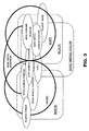
- FIG. 3 shows a conceptual representation illustrating all of colors, hardness, compositions and structures as features in the micro of such WEA.
- This stress theory qualitatively takes the form involving the most of WEA faces. That is, suppose the Hertz's contact circle (or ellipsoid) has a radius "a", a repeated shear stress "max" occurs in parallel to the surface at a depth of 0.5a from the surface and, if the white bands occur in such a portion (with WEA appearing in parallel to the surface), there is a macro face as shown in FIG. 1A and 2A. Moreover, this portion has an increased dislocation density to cause the solute atoms to move due to diffusion thereby forming an area rich in C, Cr, Si and a lean portion in opposite position. In addition, it becomes possible to explain that the voids are also able to occur due to a Kirkendall effect. However, it is a convenient theory that although it is hard to explain the occurrence of localized plastic flow and plastic strain, most of the cases can be explained.
- This load W takes a large value 3 to 70 times that of an actually measured value.
- the presence of such a huge load exceeds a load in a range that is not obtained by a housing of a body of the alternator (with no abnormality seen in the housing in actual practice).
- the present invention has been completed with a view to addressing such issues and has an object to provide a method of designing a rolling bearing in a clear, correct and simple mechanism so as to address brittle flaking.
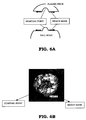
- FIG. 6A is a typical view showing an area around a starting point of the flaking
- FIG. 6B is a photograph with the flaked segment, shown in FIG. 6A, is viewed from a lower area
- FIG. 6C is a photograph of a cross-section of a ball body
- FIG. 6D shows an enlarged photograph of a part surrounded in an ellipsoid shown in FIG. 6C.
- a mountain is present on the ball body (see FIG. 6C) and a mountaintop was found to be the starting point of the flaking.
- White bands are present in an area straddling a vicinity of the mountaintop and a base thereof.
- a crack does not develop in parallel (in a direction ⁇ in a polar coordinate display) beginning at the interior of the ball into the flaking (in a direction ⁇ o at a depth Z o in the Palmgren doctrine of a bearing...in a so-called dynamic shear direction) but the crack develops along a slope of the mountain, beginning at an area closer (may be a surface) to a surface of the ball, down to the base of the mountain from which the crack runs in a planar direction (chord component...not in the direction ⁇ ) with the resultant occurrence of flaking in a final stage.
- the flaked segment has disappeared, several pieces of residual polish surfaces of the ball were found on the starting point of the flaking of the ball body. That is, a so-called surface originating flaking, in which the mountaintop peeks out on the ball surface, was clearly found.
- the above theories have mutually conflicting characteristics.
- the features 9 and 10 are opposite to each other. From the features 9, 10 and the feature 8, although a need arises for applying a certain amount of load in order to cause the brittle flaking to take place but the load should not exceeds far beyond the certain load.
- the greater the varying load the more frequent will be for the flaking to take place, it's not like there is an evident ground, it's still more difficult to make scientific explanation.
- the adiabatic shear deformation is a plastic instable phenomenon that is present under high deformation rates.
- white-colored transformation shear bands are observed in high-tension steel and also referred to as white bands that result from a phase in which shear deformation is locally generated to heat a localized area to temperatures beyond a transformation point whereby the localized area is transformed to austenite and further transformed to martensite due to subsequent quenching. Interiors of the bands are hardened to a hardness higher than that realized in normal heat treatment. For this reason, the white bands are also known as "untempered Martensite".
- the white bands have various features like those mentioned above and we have come to the conclusion that all of these features correspond to the face of the brittle flaking.
- the present invention provides a method of designing a mechanical element provided with a rolling contact realized between two components one of which is a rolling element and the other of which is either a rolling element or a stationary element, comprising steps of; determining whether or not adiabatic shear bands have a potential for occurrence within at least one of the components, due to the fact that stress is applied to the components, thus causing high deformation rates in the at least one of the components to cause an unstable plastic phenomenon that brings about an adiabatic shear deformation state within the at least one of the components; and estimating that brittle flaking resulting from the adiabatic shear bands have a potential for occurrence within the at least one of the components, when it is determined that the adiabatic shear bands have a potential for occurrence.
- the present invention provides a method of designing a rolling bearing provided with components including rolling elements, an outer ring, and an inner ring which come into contact with each other, comprising steps of:
- the main essence of the present invention according to the above aspects is based on an analysis conducted by the inventors.
- the generation mechanism of the WEA which causes brittle flaking in rolling bearings serving as rolling contact parts
- the inventors' analysis shows that such mechanism results from an unstable plastic deformation under high deformation rates, that is, an adiabatic shear deformation. Therefore, it has been known that this WEA is similar to an adiabatic shear band whose mechanism has already been figured out an impact-engineering field. Thanks to this fact, it is comprehensive that suppressing an adiabatic shear deformation from occurring will lead to no brittle flaking.
- the generation mechanism of the WEA which causes brittle flaking in rolling bearings serving as rolling contact parts
- the inventors' analysis shows that such mechanism results from an unstable plastic deformation under high deformation rates, that is, an adiabatic shear deformation. Therefore, it has been known that this WEA is similar to an adiabatic shear band whose mechanism has already been figured out an impact-engineering
- the foregoing determination step includes steps of:
- C v is a volume specific heat
- n is a work hardening exponent in parabolic hardening
- Y' is a yield stress of shear
- k is a slope in linear hardening.
- This configuration provides a practical value of the critical shear strain ⁇ c using characteristics of materials to be designated based on the test results of various materials. It is thus possible to precisely grasp and estimate degrees showing how easily the adiabatic shear bands are caused. This is highly useful for developing the materials of bearings.
- the critical shear strain ⁇ c is given as 0.08 serving as a threshold for determining whether or not the adiabatic shear bands have a potential for occurrence.
- the adiabatic shear bands are observed as being white (i.e., also called white bands), making the white layers on a bearing clearer. Furthermore, a practical value of the critical shear strain can be given as 0.08. This is greatly helpful, because there is no need for searching for material data on material manuals.
- the determining step is configured to determine that the adiabatic shear bands have no potential for occurrence, provided that a relative collision velocity v between the rolling element and the outer or inner ring in a radial direction of the rolling bearing is met by an equation of v ⁇ 1 m / sec
- the rolling bearing is incorporated in an alternator for combustion engines and contains a lubricant of which withstand pressure p is independent of both of viscosity of oil contained in grease and velocity, the lubricant including an additive such as an extreme pressure additive or solid lubricant, and the determining step is configured to determine that the adiabatic shear bands have no potential for occurrence, provided that the withstand pressure p of the lubricant is met by an equation of p > 7000 M P a
- the determining step is configured to determine that the adiabatic shear bands have no potential for occurrence, provided that a contact between the rolling element and either the outer ring or the inner ring is maintained.
- the present invention provides a program, of which data is stored in a memory and readable by a computer from the memory, for designing a bearing provided with a rolling contact, the program enabling the computer to perform steps of:
- engineers can use a computer in an easier and more accurate manner during the stage of design of a bearing in order to check whether or not there is a possibility of occurrence of brittle flaking in the bearing, with quick countermeasures taken on the spot.
- FIG. 9 shows one example of data shown in the literature disclosed by Ulric S. Lindholm and Gordon R. Johnson. As apparent from data on tool steel corresponding to material for use in the bearing, it will be appreciated that the maximum shear strain (extension) ⁇ max lies at an extremely high level ranging from 0.4 to 1.0.
- Adiabatic shear deformation bands are observed in high-tension steel as the white bands and such adiabatic shear deformation is regarded as a plastic instable phenomenon appearing under high deformation rates.
- a material characteristic during plastic deformation is given by Eq. 20 with ire presenting shear flow stress, ⁇ representing shear strain, shear strain rate and T representing temperatures as expressed below.
- ⁇ f ( ⁇ , ⁇ ⁇ , T )
- a shear work volume w per unit cubic volume and a heat quantity q per unit cubic volume are given by Formulae. 23 and 24 as indicated below.
- C v represents the volume specific heat: provided that the specific heat is multiplied with a specific weight.
- the plastic instable phenomenon in adiabatic is expressed by Eq. 26 based on Eqs. 22 and 25 as indicated below.
- 0 ⁇ ⁇ ⁇ ⁇ ) T , ⁇ ⁇ + ⁇ ⁇ ⁇ ⁇ ⁇ ) T , ⁇ d ⁇ ⁇ d ⁇ + ⁇ ⁇ ⁇ T ) ⁇ , ⁇ ⁇ ⁇ C v
- the critical shear strain ⁇ c in Eq. 31 indicates the occurrence of adiabatic shear deformation. In case of high-tension steel, the critical shear strain ⁇ c becomes a condition under which the white bands occur (provided that the material characteristic represents parabolic work hardening).
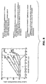
- FIG. 10 shows shear strain ⁇ , resulting from experimentations conducted by changing various heat treatment conducted on steel AIS 14340, which was actually used by him, and results indicative of the absence of or absence of adiabatic shear bands in comparison with a critical shear strain ⁇ c obtained from Eq. 31.
- the critical shear strain ⁇ c of SUJ2 lies at a value of approximately 0.1 (when the strain rate lies at 10 4 /sec).
- a value of "m" represents a mass of the ball per se when the ball encounters the collision as a single body and when the ball accretes with the outer ring and housing body of the alternator as a unitary body to collide against the inner ring, masses of the collided objects equal a total mass of associated component elements.
- FIG. 16 shows various related dimensions in a midcourse of collision, i.e., the amount X 1 of an indentation generated in the ball and the amount X 2 of an indentation generated in the inner ring (accordingly a total amount of indentations is represented by X).
- a symbol r designates a radius of the ball
- R 1 and R 2 designates a radius of curvature of the inner ring and a radius of curvature of a raceway, respectively
- a and b designate a long radius and short radius of a contact ellipsoid, respectively
- R c1 and R c2 designate common radii in the contact areas after the formation of the indentation with R c1 representing the common radius on a side phase and R c2 representing the common radius on a front side. Since the ball and the inner ring have material hardnesses that are nearly equal to each other, a formula is given below.
- the shear strains ⁇ a , ⁇ b are given by ⁇ a ⁇ 0.3 a
- R C 1 0.3 R C 1 2 R 1 r V 0 ( R 1 ⁇ r ) ⁇ p sin ⁇ p t and ⁇ b ⁇ 0.3 b
- R C 2 0.3 R C 2 2 R 2 r V 0 ( R 2 + r ) ⁇ p sin ⁇ p t
- the calculation method does not use the Hertz's elastic theory and includes the equation that can be established even in plastic region as apparent from its process.
- the shear strain ⁇ and the shear strain rate form the factors that can be calculated when the contact area vicinities are plastically deformed (with entire areas being plastically deformed) as understood from the supposition and, hence, localized plastic deformation may take place at values less than the values of the shear strain ⁇ and the shear strain rate resulting from calculations with the formulae 58, 59.
- vo 10m/ sec.
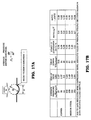
- FIG. 18A in case of such collision, it takes time of 2.2 ⁇ 10 -6 sec before the ball comes to a halt and the strain rate is 5x10 4 /sec in average with the strain ⁇ reaching a value greater than 0.09.
- final indentation depths (of both the ball and inner ring) X 1 , X 2 lie at 7 ⁇ m and the contact ellipsoid 2a, 2b lie at 0.4mmx3.5mm.
- the strain and the strain rate have smaller values than those of the case wherein the ball collides against the inner ring (with ⁇ varying from 0.09 to 0.07 in reduction by 20%). That is, assuming that the ball collides against the inner ring or the outer ring at the same speed, the inner ring exceeds the critical shear strain ⁇ c and the critical shear rate before the outer ring exceeds these critical values and the inner ring surely encounters the brittle flaking. In this sense, the same result as that obtained in the related art stress theory based on the Herzt's elastic theory is obtained (that is, when applied with the same load, the inner ring encounters larger stress than that encountered by the outer ring).
- the "impact" means in the first place that a ball bears away from one of or both of the inner ring and the outer ring for some reasons to be brought out of a contact condition (into a so-called free condition) upon which the ball is caused to be brought into contact (into collision) with the associated component part, separate times exists when the ball collides against the outer ring and when the ball collides against the inner ring.
- vo is an entirely different value. Accordingly, depending on the value of vo with respect to the inner ring and the outer ring, different magnitude relationships appear in the strain ⁇ and the strain rate.
- a colliding surface (of the outer ring or the ball) with respect to the outer ring to encounter the brittle flaking. That is, no brittle flaking takes place on the inner ring.
- FIGS. 21A and 21B show the relationship in force in cases where there is a frictional force on the way wherein the ball, shown in FIG. 16B, collides against the inner ring to cause the indentation to be formed.
- FIG. 21A shows force acting on the ball and
- FIG. 21B shows force acting on the inner ring.
- a frictional force ⁇ p acts in a direction (direction ⁇ ) away from an axis AA at a center of a convex portion of a contact surface.
- the frictional force moves in a direction (direction ⁇ ) toward an axis BB at a center of a concave portion of a contact surface as shown in FIG. 21B.
- FIGS. 22A and 22B a case wherein a tangential line force acts on a Hertz's elastic contact surface is shown in FIGS. 22A and 22B.
- FIGS. 21A and 21B there is a difference in orientation of the tangential line forces between cases of FIGS. 21A and 21B, wherein the indent (indentation) resulting from the plastic deformation is considered, and cases of FIGS. 22A and 22B for the Hertz's elastic deformation wherein no indent is considered (with a difference between a symmetry and an asymmetry with respect to the axis AA).
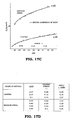
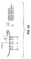
- FIG. 23 and FIGS. 23A to 23D show results upon calculating the stress in elastic deformation for the purpose of roughly understanding such differences.
- FIG. 23 and FIGS. 23A to 23D show results upon calculating the stress in elastic deformation for the purpose of roughly understanding such differences.
- FIG. 23 and FIGS. 23A to 23D show results upon calculating the stress in elastic deformation for the purpose of roughly understanding such differences.
- FIG. 23 and FIGS. 23A to 23D show results upon calculating the stress in elastic deformation for the purpose of roughly understanding such differences.
- FIGS. 23A and 23B show the distributions of stresses arising in the direction of the tangential line force shown in FIGS. 21A and 21B and FIGS. 23C and 23D show the distributions of stresses arising in the direction shown in FIGS. 22A and 22B.
- the ball 1 and the inner ring 2 have the stress distributions, which are symmetric with each other with respect to an axis Z in the presence of the tangential line force in the usual Hertz contact, and the both the ball and the inner ring have the maximum shear stress ⁇ st of 0.32 in identical values (whereas with no friction ⁇ , it is needless to say that ⁇ st lies at 0.30).
- the ball 1 upon analysis of a frontal collision of the ball (against the inner ring) this time that is supposed to encounter the brittle flaking, the ball 1 has ⁇ st laying at 0.32 and the inner ring 2 has ⁇ st laying at a value of 0.30 to be different in magnitude of the maximum shear stress.
- FIGS. 24A and 24B a strain resulting from a dent formed in soft material with a hard wedge is shown in FIGS. 24A and 24B.
- the present invention can explain the reason why the flaking occurs only in one (such as, for instance, only the ball in the presence of grease containing extreme pressure additives) of the two objects on the contact areas thereof. That is, it can be explained that when taking the influence of friction into consideration in the plastic deformation, only one object satisfies the adiabatic shear condition.
- the method of calculating ⁇ and the strain rate, forming the present invention needs a coefficient I(such as three times) to be multiplied in the presence of friction, it is more simple to be compared with the adiabatic shear condition and it is sufficiently useful to be used in actual design engineering.
- making efforts of arranging experimental data on various frictional coefficients enables an error to be simply grasped to serve as a correction coefficient, thereby making it possible for the correction coefficient to be simply used as a threshold value in judgment of the brittle flaking. That is, under an actual equipment condition, anybody can make judgment with a simple equation by conducting calculation to find whether or not the adiabatic shear condition is satisfied without executing hard calculation such as the FEM or the like.
- the brittle flaking is influenced in the presence of or absence of extreme pressure additives.
- An average pressure p at the contact area in the way in which the outer ring is hollowed (or the ball is hollowed due to collision of the outer ring) reaches 4800MPa (Eq.
- the extreme pressure additives providing the lubrication (with no need for the rotational speed) unfounded on the EHL theory, do not increase the frictional coefficient ⁇ and do not exceed ⁇ c , no brittle flaking takes in the outer ring (particularly under circumstances where the pressure has a value as high as 4800MPa like the present case, the extreme pressure additives become effective).
- the extreme pressure additives which have no need for the speed to achieve lubrication, fly in all directions from the rotating inner ring (although such flying of the extreme pressure additives is effective for the lubricating condition resulting from oil content based on the EHL theory) due to a centrifugal force thereof.
- the contact area between the ball and the inner ring suffers from a shortage of the extreme pressure additives at all times with no capability of lubricating the indentation caused by the collision, resulting in an increase in the friction coefficient to cause the brittle flaking to take place in the ball.
- the effect of the extreme pressure additives, formed of grease, according to the present invention can be excellently explained. (It is easily speculated that oil content, prevailing in the contact area in the course of plastic deformation, is compressed under a hermetically sealed condition and exposed to high temperatures and high loads and dissolved into hydrogen that enters an inside of the bearing. That is, when applied with the impact to the extent in that the brittle flaking takes place, things are going for hydrogen to be observed.)
- FIG. 26A represents a status in which a radial load and thrust load act on the ball from the outer ring toward the inner ring 2 of the ball bearing in a direction as shown by whitened arrows (with the loads being relatively identical even when applied not from the outer ring but from the inner ring).
- FIG. 26B is an enlarged view of a contact area between the ball and the inner ring shown in FIG. 26A.
- the ball 1 is held in contact with the inner ring at a point deviated from a center of the inner ring 2 by ⁇ and the ball 1 is located at a position that is elevated from a bottom of a bearing ring of the inner ring 2 by h.
- the thrust load has no need to be of the type that is forcibly applied as a preliminary pressure but may be of a thrust component resulting from an inclination of an axis caused by the radial load and the point is that everything is sufficed if the deviation occurs by ⁇ from the center of the inner ring.
- 61 can be applied to a situation under which the ball becomes free, due to some reasons (even if a contact point is initially deviated by ⁇ ), to have a potential energy with a height h. There is a probability that a belt tension instantaneously becomes negative during deceleration of the engine as observed in, for instance, a serpentine drive. When this takes place, the bearing entirely has no load to release the contact between the ball and the inner ring or the outer ring and, upon termination of the deceleration, the ball is exerted with the load again, causing the ball to encounter the collision.
- FIG. 28 shows a mechanism, forming the method of the present invention, in which the brittle flaking occurs in the bearing.
- the adiabatic shear deformation theory it becomes possible to explain not only the micro and macro faces (statuses) in the bearing resulting from the brittle flaking based on the white bands but also features as viewed in terms of the phenomenalism set forth above.
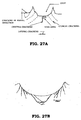
- the feature 1 indicates that the macro face is caused by the collision (see FIGS. 27A and 27B) is related.
- the feature 2 represents that the collision of the ball has no directional characteristic (with no effect from restriction in a direction in which a fixed load is exerted).
- the feature 3 is verified that the WEA varies due to a difference in the degree of the adiabatic shear condition.
- the feature 4 results from a phase in that the adiabatic shear deformation causes material to be hardened with a hardness greater than that realized in usual heat treatment.
- the feature 5 comes from a reason in that there is the adiabatic shear deformation forming a plastically unstable phenomenon.
- the localized plastic flow and plastic strain are caused by adiabatic shear deformation that is the plastic instable phenomenon.
- the feature 6 depends on a difference in an impact speed, a difference in a friction coefficient (involved in positive and negative values) and a degree of a curvature.
- the feature 7 is an issue of an impact speed and a magnitude of a mass and has no relationship with a bearing load capacity.
- the feature 8 is confirmed such that the greater the fluctuation band in stress, the greater will be the probability for the ball to enter a free state.
- the feature 9 is verified such that the ball cannot be accelerated unless the radial load increases to some extent (Eq. 61).
- the causes of the brittle flaking is clarified to be derived from the adiabatic shear deformation, which forms the plastically instable phenomenon occurring under the high shear strain-rate deformation, while indicating the critical values (of ⁇ c , 10 2 /sec) of the strain and the strain rate that have an influence on the occurrence of such adiabatic shear deformation whereas the causes by which the adiabatic shear deformation takes place are clarified to be the impact phenomenon for thereby permitting every body to execute the calculations of the strain and the strain rate, at which the adiabatic shear deformation takes place, using the simple calculation formulae without using specialized methods, such as the FEM or the like, that take time.
- the designing method of the present invention should satisfies the requirements wherein Radial Load ⁇ Thrust Load (with h and ⁇ needed to lie at small values), tension of a belt needs not to take a negative value caused by an adverse affect resulting from an inertial force even during deceleration of an engine and a frequency of engine explosions needs not be coincident with a characteristic frequency of the belt and a characteristic frequency of an auxiliary unit body.
- FIG. 30A is a schematic view of a test machine to show a condition such as a revolution speed pattern.
- the test machine was set so as to include a resonance in a lateral direction of the belt in the way of up and down fluctuations in the motor revolution (with the belt resonating at a magnitude of 2G that can be neglected as compared to the actual engine vibrations with the magnitude of 20 to 30G).
- FIG. 30B shows a photograph of a raceway of the inner ring.
- a mark of an indentation formed in an ellipsoid with a long diameter 2.6mm was observed (with the photograph being taken in an oblique direction to cause the mark to be viewed in a falcated shape due to the influence of a curvature).
- the ellipsoid has a trouble to be viewed at a central area thereof due to the influence of racing of the ball, but it seems that the ellipsoid has a short diameter of approximately 0.32mm with a depth greater than 1 ⁇ m.
- the present inventors have conducted a test under a condition wherein in order to clarify stress factors, the motor revolution speed was fixed at a value of 700 ⁇ 10 rpm (at a value corresponding to a resonant point of a belt), the ball is similarly flaked.
- the vertical vibration f 2 has a portion, deviated from a value of Eq. 63 due to interactions of all the pulleys on which the belts are tensioned, which takes a characteristic value and there are the same number of characteristic frequencies as that of the pulleys.
- the design technique according to the present invention will not be confined to the rolling bearings, but can widely be applied to mechanical element parts having rolling contacts.
- any parts can enjoy the merits of the design according to the present invention, as long as there is a potential for occurrence of brittle flaking resultant from adiabatic shear bands due to adiabatic shear deformations in cases where stress is applied to such rolling contacts between a rolling member and a stationary member or between two rolling members.
- Such a contact (parts) is therefore included in transmissions (such as continuously variable transmission (CVT)) and a contact on a tooth plane of a gearwheel as well as the rolling bearings.
- the rolling bearing includes a ball bearing, a roller bearing, and a needle bearing.
- the adiabatic shear bands do not always appear in white, as already been mentioned.
- the adiabatic shear bands are observed as being white, while in the case of using general steel and non-iron metal, they are observed as being non-white colors such as black. Regardless of differences in such colors, materials other than the high-tension steel still need to suppress adiabatic shear bands from occurring therein, because brittle flaking will occur in an extremely short time once the adiabatic shear bands occur.
- the design technique according to the present invention can be used effectively for such materials other than the high-tension steel.
- the determination and estimation of probability for occurrence of brittle flaking in rolling contacts can be conducted by any engineers in an easier and more accurate fashion, with no much dependence on veteran engineers' experience and on fragile determined and estimated results.
- an engineer can use a personal computer with spreadsheet programs to conduct the determination and estimation, in which results (that is, results showing whether or not there is a potential for occurrence of brittle flaking) can be obtained within one minute from entering data, providing an excellent advantage in designing the rolling contact parts.
- FIGS. 31 and 32 the configurations for determining brittle flaking which may occur in a ball bearing are illustrated in FIGS. 31 and 32, where FIG. 31 outlines a block diagram of a personal computer (computer) 101 used by an engineer and FIG. 32 outlines processing carried out by the computer 101 for the determination.
- the computer 101 shown in FIG.31 is provided with an interface 102, CPU (central processing unit) 103, ROM (read-only memory) 104, RAM (random access memory) 105, input device 106, and display 107.
- CPU central processing unit
- ROM read-only memory
- RAM random access memory
- input device 106 input device
- display 107 display 107.
- the CPU 103 executes a program exemplified in FIG. 32 and data of the program is installed in the ROM 104 in advance.
- the program show ⁇ in FIG. 32 is written to accomplish the determination and estimation of brittle flaking based on the concept according to the present invention.
- the CPU 32 operates to read the data for the determination and estimation from the ROM 104 and becomes ready for engineer's input operations (step S1 to S3).
- Such input operations include input of dimensions (the diameter of a ball, the curvature diameter of an inner ring, the diameter of the inner ring, and others), input of material characteristics (a critical shear stress strain ⁇ c , a critical shear stain rate ⁇ c , a flow stress Y) and input of impact conditions (an impact velocity Vo and the mass m of a rolling member).
- step S4 the CPU 103 carries out computation based on necessary formulae such as Eqs,. (58), (59), and others to obtain a strain ⁇ to be predicted and a strain rate ⁇ to be predicted (step S4).
- the CPU 103 proceeds to step S105, where whether or not there is a potential for occurrence of adiabatic shear deformations is determined by making a comparison between the values ⁇ and ⁇ c , and between the values ⁇ and ⁇ c . Specifically, the comparison of ⁇ > ⁇ c and the comparison of ⁇ > ⁇ c are carried out concurrently.
- step S6 When the compared results reveal that both the conditions ⁇ > ⁇ c and ⁇ > ⁇ c , are not realized concurrently (NO thereat), the CPU 103 concludes that there is no potential for occurrence of adiabatic shear bands (normal; step S6). In contrast, when the compared results reveal that both the conditions ⁇ > ⁇ c and ⁇ > ⁇ c are realized concurrently (YES thereat), the CPU 103 concludes that there is a potential for occurrence of adiabatic shear bands (step S7). That is, in this case, it is recognized that the ball bearing may be subjected to brittle flaking (i.e., white band flaking), if actually used.
- brittle flaking i.e., white band flaking
- the mechanism is clarified by the present invention and there is a clear threshold (target value) for the brittle flaking to be prevented whereby it becomes possible to achieve design and study in advance. Also, clear measures can be undertaken and no need arises for implementing a tremendously inefficient method like those of the related art requiring tests in an actual machine for confirmation. Further, judgment of the test results can be made in the light of the mechanism with no errors. In addition, no need arises for the bearing to have an unnecessarily large size or to have a precision. In such a way, the design method of the present invention has an excellent advantage in that the design can be correctly made to address the occurrence of the brittle flaking, encountered by the rolling bearing, in a simple fashion.
Landscapes
- Engineering & Computer Science (AREA)
- General Engineering & Computer Science (AREA)
- Physics & Mathematics (AREA)
- Theoretical Computer Science (AREA)
- Geometry (AREA)
- General Physics & Mathematics (AREA)
- Mechanical Engineering (AREA)
- Evolutionary Computation (AREA)
- Computer Hardware Design (AREA)
- Computational Mathematics (AREA)
- Mathematical Analysis (AREA)
- Mathematical Optimization (AREA)
- Pure & Applied Mathematics (AREA)
- Rolling Contact Bearings (AREA)
Applications Claiming Priority (2)
| Application Number | Priority Date | Filing Date | Title |
|---|---|---|---|
| JP2005018916 | 2005-01-26 | ||
| JP2005025437 | 2005-02-01 |
Publications (2)
| Publication Number | Publication Date |
|---|---|
| EP1686500A2 true EP1686500A2 (de) | 2006-08-02 |
| EP1686500A3 EP1686500A3 (de) | 2007-04-04 |
Family
ID=36075107
Family Applications (1)
| Application Number | Title | Priority Date | Filing Date |
|---|---|---|---|
| EP05013729A Withdrawn EP1686500A3 (de) | 2005-01-26 | 2005-06-24 | Verfahren und Vorrichtung zum Design von Kugellagern unter Vermeidung von sprödheitsbedingtem Abschiefern |
Country Status (3)
| Country | Link |
|---|---|
| US (1) | US20060064197A1 (de) |
| EP (1) | EP1686500A3 (de) |
| CA (1) | CA2510685A1 (de) |
Cited By (1)
| Publication number | Priority date | Publication date | Assignee | Title |
|---|---|---|---|---|
| EP1748371A1 (de) * | 2005-07-26 | 2007-01-31 | Denso Corporation | Apparat und Methode zum Klassifizieren von Schadensmustern rollender Kontakte |
Families Citing this family (8)
| Publication number | Priority date | Publication date | Assignee | Title |
|---|---|---|---|---|
| CN103344482B (zh) * | 2013-07-05 | 2015-04-29 | 湖南大学 | 一种基于计算反求的混凝土材料动态本构参数识别方法 |
| US10295475B2 (en) | 2014-09-05 | 2019-05-21 | Rolls-Royce Corporation | Inspection of machined holes |
| WO2016099375A1 (en) * | 2014-12-16 | 2016-06-23 | Aktiebolaget Skf | Bearing component and method of manufacture |
| US10228669B2 (en) | 2015-05-27 | 2019-03-12 | Rolls-Royce Corporation | Machine tool monitoring |
| JP6672056B2 (ja) * | 2016-04-22 | 2020-03-25 | 三菱重工サーマルシステムズ株式会社 | ターボ圧縮機、これを備えたターボ冷凍装置 |
| CN111157338B (zh) * | 2020-01-08 | 2021-09-17 | 吉林大学 | 一种金属哑铃型试样大应变范围压缩硬化曲线的测量方法 |
| CN114707270B (zh) * | 2022-04-06 | 2024-08-30 | 西南石油大学 | 一种基于管材塑性失效准则的油气井管柱强度设计方法 |
| CN117521462B (zh) * | 2023-11-15 | 2024-07-30 | 南通大学 | 一种考虑成熟度的果实脱落预测有限元模型构建方法 |
Family Cites Families (4)
| Publication number | Priority date | Publication date | Assignee | Title |
|---|---|---|---|---|
| JPS60249722A (ja) * | 1984-05-22 | 1985-12-10 | Yasuo Ueno | ころがり軸受 |
| GB2352202B (en) * | 1999-02-19 | 2003-05-28 | Suncall Corp | Spring with excellent fatigue endurance property and surface treatment method for producing the spring |
| JP4427195B2 (ja) * | 2001-01-26 | 2010-03-03 | Ntn株式会社 | 自動車用グリース封入軸受 |
| JP4228725B2 (ja) * | 2003-02-28 | 2009-02-25 | 株式会社ジェイテクト | 転がり、摺動部品の製造方法および転がり軸受 |
-
2005
- 2005-06-15 US US11/152,722 patent/US20060064197A1/en not_active Abandoned
- 2005-06-24 EP EP05013729A patent/EP1686500A3/de not_active Withdrawn
- 2005-06-27 CA CA002510685A patent/CA2510685A1/en not_active Abandoned
Cited By (2)
| Publication number | Priority date | Publication date | Assignee | Title |
|---|---|---|---|---|
| EP1748371A1 (de) * | 2005-07-26 | 2007-01-31 | Denso Corporation | Apparat und Methode zum Klassifizieren von Schadensmustern rollender Kontakte |
| US7577555B2 (en) | 2005-07-26 | 2009-08-18 | Denso Corporation | Apparatus and method for determining patterns of damage being caused in rolling contact element |
Also Published As
| Publication number | Publication date |
|---|---|
| EP1686500A3 (de) | 2007-04-04 |
| US20060064197A1 (en) | 2006-03-23 |
| CA2510685A1 (en) | 2006-07-26 |
Similar Documents
| Publication | Publication Date | Title |
|---|---|---|
| Gegner | Tribological aspects of rolling bearing failures | |
| Ne´ lias et al. | Detrimental effects of debris dents on rolling contact fatigue | |
| US7577555B2 (en) | Apparatus and method for determining patterns of damage being caused in rolling contact element | |
| Dragobetskii et al. | Method of determination of technological durability of plastically deformed sheet parts of vehicles | |
| EP1686500A2 (de) | Verfahren und Vorrichtung zum Design von Kugellagern unter Vermeidung von sprödheitsbedingtem Abschiefern | |
| Bruce et al. | Threshold maps for inclusion-initiated micro-cracks and white etching areas in bearing steel: the role of impact loading and surface sliding | |
| Qin et al. | Effects of water contamination on micropitting and rolling contact fatigue of bearing steels | |
| Sirata | Fatigue failure analysis of crankshafts-a review | |
| JP7272767B2 (ja) | 円錐ころ軸受 | |
| Chiu | The mechanism of bearing surface fatigue–-experiments and theories | |
| Narita et al. | Simulation of rolling contact fatigue strength for traction drive elements | |
| Bruce | Analysis of the premature failure of wind turbine gearbox bearings | |
| Hasegawa et al. | Estimation Method of Micropitting Life from SN Curve Established by Residual Stress Measurements and Numerical Contact Analysis | |
| Takahashi et al. | Effects of axial clearance on surface initiated flaking in tapered roller bearings | |
| Li et al. | Parameter investigation of bearing based on rolling–sliding contact fatigue crack growth considering load history | |
| Murakami et al. | Long life bearings for automotive alternator applications | |
| JP2006242376A (ja) | 転がり軸受の設計方法及び設計装置 | |
| Liou et al. | Finite Element Analysis of Residual Stress in Ti‐6Al‐4V Alloy Plate Induced by Deep Rolling Process under Complex Roller Path | |
| Gegner et al. | Service Loading of Rolling Bearings in Wind Turbine Gearboxes: X-ray Diffraction Material Response Analysis of White Etching Crack Premature Failures | |
| Neisi et al. | Stress analysis of a touchdown bearing having an artificial crack | |
| JPH0861372A (ja) | 表面硬化処理層を有する軸受 | |
| Narita et al. | Simulation of rolling contact fatigue strength for traction drive elements (comparison with fatigue test) | |
| Moore et al. | Crankshaft failure and why it may happen again | |
| US7618193B2 (en) | Rolling bearing incorporated in auxiliary device for internal combustion engine | |
| Vullo | Surface Durability (Pitting) of Spur and Helical Gears |
Legal Events
| Date | Code | Title | Description |
|---|---|---|---|
| PUAI | Public reference made under article 153(3) epc to a published international application that has entered the european phase |
Free format text: ORIGINAL CODE: 0009012 |
|
| AK | Designated contracting states |
Kind code of ref document: A2 Designated state(s): AT BE BG CH CY CZ DE DK EE ES FI FR GB GR HU IE IS IT LI LT LU MC NL PL PT RO SE SI SK TR |
|
| AX | Request for extension of the european patent |
Extension state: AL BA HR LV MK YU |
|
| PUAL | Search report despatched |
Free format text: ORIGINAL CODE: 0009013 |
|
| AK | Designated contracting states |
Kind code of ref document: A3 Designated state(s): AT BE BG CH CY CZ DE DK EE ES FI FR GB GR HU IE IS IT LI LT LU MC NL PL PT RO SE SI SK TR |
|
| AX | Request for extension of the european patent |
Extension state: AL BA HR LV MK YU |
|
| 17P | Request for examination filed |
Effective date: 20070425 |
|
| AKX | Designation fees paid |
Designated state(s): DE FR GB IT SE |
|
| STAA | Information on the status of an ep patent application or granted ep patent |
Free format text: STATUS: THE APPLICATION IS DEEMED TO BE WITHDRAWN |
|
| 18D | Application deemed to be withdrawn |
Effective date: 20101231 |