EP1686203B1 - Kohlenstoffnanofaserstab und faserförmiger nanokohlenstoff sowie verfahren und vorrichtung zur herstellung von faserförmigem nanokohlenstoff - Google Patents
Kohlenstoffnanofaserstab und faserförmiger nanokohlenstoff sowie verfahren und vorrichtung zur herstellung von faserförmigem nanokohlenstoff Download PDFInfo
- Publication number
- EP1686203B1 EP1686203B1 EP03774132A EP03774132A EP1686203B1 EP 1686203 B1 EP1686203 B1 EP 1686203B1 EP 03774132 A EP03774132 A EP 03774132A EP 03774132 A EP03774132 A EP 03774132A EP 1686203 B1 EP1686203 B1 EP 1686203B1
- Authority
- EP
- European Patent Office
- Prior art keywords
- fibrous
- fluidized bed
- carbon
- carbon nano
- catalyst
- Prior art date
- Legal status (The legal status is an assumption and is not a legal conclusion. Google has not performed a legal analysis and makes no representation as to the accuracy of the status listed.)
- Expired - Lifetime
Links
- OKTJSMMVPCPJKN-UHFFFAOYSA-N Carbon Chemical compound [C] OKTJSMMVPCPJKN-UHFFFAOYSA-N 0.000 title claims abstract description 278
- 229910052799 carbon Inorganic materials 0.000 title claims abstract description 273
- 229910021392 nanocarbon Inorganic materials 0.000 title claims abstract description 256
- 238000000034 method Methods 0.000 title description 43
- 239000003054 catalyst Substances 0.000 claims description 199
- 239000000463 material Substances 0.000 claims description 160
- 239000007789 gas Substances 0.000 claims description 149
- 239000012530 fluid Substances 0.000 claims description 128
- 239000001257 hydrogen Substances 0.000 claims description 66
- 229910052739 hydrogen Inorganic materials 0.000 claims description 66
- UFHFLCQGNIYNRP-UHFFFAOYSA-N Hydrogen Chemical compound [H][H] UFHFLCQGNIYNRP-UHFFFAOYSA-N 0.000 claims description 62
- 239000003575 carbonaceous material Substances 0.000 claims description 59
- 239000002245 particle Substances 0.000 claims description 54
- 238000010438 heat treatment Methods 0.000 claims description 49
- VYPSYNLAJGMNEJ-UHFFFAOYSA-N Silicium dioxide Chemical compound O=[Si]=O VYPSYNLAJGMNEJ-UHFFFAOYSA-N 0.000 claims description 42
- 238000004519 manufacturing process Methods 0.000 claims description 38
- 239000000203 mixture Substances 0.000 claims description 36
- 230000001603 reducing effect Effects 0.000 claims description 27
- 239000000835 fiber Substances 0.000 claims description 23
- 239000011230 binding agent Substances 0.000 claims description 22
- 239000000047 product Substances 0.000 claims description 19
- 239000011261 inert gas Substances 0.000 claims description 17
- 229910052751 metal Inorganic materials 0.000 claims description 17
- 239000002184 metal Substances 0.000 claims description 17
- 210000003746 feather Anatomy 0.000 claims description 16
- 229910052742 iron Inorganic materials 0.000 claims description 15
- 238000011084 recovery Methods 0.000 claims description 15
- 230000003197 catalytic effect Effects 0.000 claims description 13
- PNEYBMLMFCGWSK-UHFFFAOYSA-N aluminium oxide Inorganic materials [O-2].[O-2].[O-2].[Al+3].[Al+3] PNEYBMLMFCGWSK-UHFFFAOYSA-N 0.000 claims description 12
- 238000007599 discharging Methods 0.000 claims description 9
- 239000000377 silicon dioxide Substances 0.000 claims description 9
- 239000012298 atmosphere Substances 0.000 claims description 8
- 239000006229 carbon black Substances 0.000 claims description 8
- 229910052759 nickel Inorganic materials 0.000 claims description 6
- 238000007664 blowing Methods 0.000 claims description 5
- 239000007795 chemical reaction product Substances 0.000 claims description 4
- 239000004576 sand Substances 0.000 claims description 4
- 229910000323 aluminium silicate Inorganic materials 0.000 claims description 3
- 229910052802 copper Inorganic materials 0.000 claims description 3
- HNPSIPDUKPIQMN-UHFFFAOYSA-N dioxosilane;oxo(oxoalumanyloxy)alumane Chemical compound O=[Si]=O.O=[Al]O[Al]=O HNPSIPDUKPIQMN-UHFFFAOYSA-N 0.000 claims description 3
- 150000002739 metals Chemical class 0.000 claims description 3
- 229910052750 molybdenum Inorganic materials 0.000 claims description 3
- 150000002500 ions Chemical class 0.000 claims 1
- 238000006243 chemical reaction Methods 0.000 description 34
- XEEYBQQBJWHFJM-UHFFFAOYSA-N Iron Chemical compound [Fe] XEEYBQQBJWHFJM-UHFFFAOYSA-N 0.000 description 28
- 230000005540 biological transmission Effects 0.000 description 28
- VNWKTOKETHGBQD-UHFFFAOYSA-N methane Chemical compound C VNWKTOKETHGBQD-UHFFFAOYSA-N 0.000 description 21
- 239000010453 quartz Substances 0.000 description 20
- UGFAIRIUMAVXCW-UHFFFAOYSA-N Carbon monoxide Chemical compound [O+]#[C-] UGFAIRIUMAVXCW-UHFFFAOYSA-N 0.000 description 17
- 229910002091 carbon monoxide Inorganic materials 0.000 description 17
- PXHVJJICTQNCMI-UHFFFAOYSA-N Nickel Chemical compound [Ni] PXHVJJICTQNCMI-UHFFFAOYSA-N 0.000 description 15
- 239000001307 helium Substances 0.000 description 15
- 229910052734 helium Inorganic materials 0.000 description 15
- SWQJXJOGLNCZEY-UHFFFAOYSA-N helium atom Chemical compound [He] SWQJXJOGLNCZEY-UHFFFAOYSA-N 0.000 description 15
- 238000005087 graphitization Methods 0.000 description 14
- 239000000126 substance Substances 0.000 description 14
- 230000005641 tunneling Effects 0.000 description 14
- 239000002134 carbon nanofiber Substances 0.000 description 12
- 238000001556 precipitation Methods 0.000 description 11
- MVFCKEFYUDZOCX-UHFFFAOYSA-N iron(2+);dinitrate Chemical compound [Fe+2].[O-][N+]([O-])=O.[O-][N+]([O-])=O MVFCKEFYUDZOCX-UHFFFAOYSA-N 0.000 description 10
- 239000002244 precipitate Substances 0.000 description 10
- MWUXSHHQAYIFBG-UHFFFAOYSA-N nitrogen oxide Inorganic materials O=[N] MWUXSHHQAYIFBG-UHFFFAOYSA-N 0.000 description 9
- 230000027455 binding Effects 0.000 description 8
- 238000005469 granulation Methods 0.000 description 8
- 230000003179 granulation Effects 0.000 description 8
- ATRRKUHOCOJYRX-UHFFFAOYSA-N Ammonium bicarbonate Chemical compound [NH4+].OC([O-])=O ATRRKUHOCOJYRX-UHFFFAOYSA-N 0.000 description 7
- 229910000013 Ammonium bicarbonate Inorganic materials 0.000 description 7
- 235000012538 ammonium bicarbonate Nutrition 0.000 description 7
- 239000001099 ammonium carbonate Substances 0.000 description 7
- 230000000052 comparative effect Effects 0.000 description 7
- KBJMLQFLOWQJNF-UHFFFAOYSA-N nickel(ii) nitrate Chemical compound [Ni+2].[O-][N+]([O-])=O.[O-][N+]([O-])=O KBJMLQFLOWQJNF-UHFFFAOYSA-N 0.000 description 7
- 238000001179 sorption measurement Methods 0.000 description 7
- XLYOFNOQVPJJNP-UHFFFAOYSA-N water Substances O XLYOFNOQVPJJNP-UHFFFAOYSA-N 0.000 description 7
- WHXSMMKQMYFTQS-UHFFFAOYSA-N Lithium Chemical compound [Li] WHXSMMKQMYFTQS-UHFFFAOYSA-N 0.000 description 6
- 239000000969 carrier Substances 0.000 description 6
- 239000007772 electrode material Substances 0.000 description 6
- 229910052744 lithium Inorganic materials 0.000 description 6
- 239000000243 solution Substances 0.000 description 6
- 229910001030 Iron–nickel alloy Inorganic materials 0.000 description 5
- ATUOYWHBWRKTHZ-UHFFFAOYSA-N Propane Chemical compound CCC ATUOYWHBWRKTHZ-UHFFFAOYSA-N 0.000 description 5
- 239000000853 adhesive Substances 0.000 description 5
- 230000001070 adhesive effect Effects 0.000 description 5
- 230000004323 axial length Effects 0.000 description 5
- 238000003795 desorption Methods 0.000 description 5
- 238000000926 separation method Methods 0.000 description 5
- 229910009112 xH2O Inorganic materials 0.000 description 5
- VGGSQFUCUMXWEO-UHFFFAOYSA-N Ethene Chemical compound C=C VGGSQFUCUMXWEO-UHFFFAOYSA-N 0.000 description 4
- 239000005977 Ethylene Substances 0.000 description 4
- 125000004432 carbon atom Chemical group C* 0.000 description 4
- 239000004020 conductor Substances 0.000 description 4
- 238000010276 construction Methods 0.000 description 4
- 229910002804 graphite Inorganic materials 0.000 description 4
- 239000010439 graphite Substances 0.000 description 4
- 150000002431 hydrogen Chemical class 0.000 description 4
- UGKDIUIOSMUOAW-UHFFFAOYSA-N iron nickel Chemical compound [Fe].[Ni] UGKDIUIOSMUOAW-UHFFFAOYSA-N 0.000 description 4
- 238000005304 joining Methods 0.000 description 4
- 238000001000 micrograph Methods 0.000 description 4
- 230000008569 process Effects 0.000 description 4
- UHOVQNZJYSORNB-UHFFFAOYSA-N Benzene Chemical compound C1=CC=CC=C1 UHOVQNZJYSORNB-UHFFFAOYSA-N 0.000 description 3
- 238000001069 Raman spectroscopy Methods 0.000 description 3
- YXFVVABEGXRONW-UHFFFAOYSA-N Toluene Chemical compound CC1=CC=CC=C1 YXFVVABEGXRONW-UHFFFAOYSA-N 0.000 description 3
- 239000003463 adsorbent Substances 0.000 description 3
- 239000012300 argon atmosphere Substances 0.000 description 3
- 230000001276 controlling effect Effects 0.000 description 3
- 230000000694 effects Effects 0.000 description 3
- 238000010894 electron beam technology Methods 0.000 description 3
- 238000002474 experimental method Methods 0.000 description 3
- 238000005243 fluidization Methods 0.000 description 3
- VLKZOEOYAKHREP-UHFFFAOYSA-N n-Hexane Chemical compound CCCCCC VLKZOEOYAKHREP-UHFFFAOYSA-N 0.000 description 3
- 229920000642 polymer Polymers 0.000 description 3
- 239000000523 sample Substances 0.000 description 3
- 238000001228 spectrum Methods 0.000 description 3
- 238000003756 stirring Methods 0.000 description 3
- 239000012808 vapor phase Substances 0.000 description 3
- KXGFMDJXCMQABM-UHFFFAOYSA-N 2-methoxy-6-methylphenol Chemical compound [CH]OC1=CC=CC([CH])=C1O KXGFMDJXCMQABM-UHFFFAOYSA-N 0.000 description 2
- IJGRMHOSHXDMSA-UHFFFAOYSA-N Atomic nitrogen Chemical compound N#N IJGRMHOSHXDMSA-UHFFFAOYSA-N 0.000 description 2
- LFQSCWFLJHTTHZ-UHFFFAOYSA-N Ethanol Chemical compound CCO LFQSCWFLJHTTHZ-UHFFFAOYSA-N 0.000 description 2
- 238000013313 FeNO test Methods 0.000 description 2
- LRHPLDYGYMQRHN-UHFFFAOYSA-N N-Butanol Chemical compound CCCCO LRHPLDYGYMQRHN-UHFFFAOYSA-N 0.000 description 2
- 229910002651 NO3 Inorganic materials 0.000 description 2
- NHNBFGGVMKEFGY-UHFFFAOYSA-N Nitrate Chemical compound [O-][N+]([O-])=O NHNBFGGVMKEFGY-UHFFFAOYSA-N 0.000 description 2
- 238000002441 X-ray diffraction Methods 0.000 description 2
- 230000015572 biosynthetic process Effects 0.000 description 2
- 239000000919 ceramic Substances 0.000 description 2
- 229910052681 coesite Inorganic materials 0.000 description 2
- 239000002131 composite material Substances 0.000 description 2
- 239000004567 concrete Substances 0.000 description 2
- 238000010924 continuous production Methods 0.000 description 2
- RKTYLMNFRDHKIL-UHFFFAOYSA-N copper;5,10,15,20-tetraphenylporphyrin-22,24-diide Chemical compound [Cu+2].C1=CC(C(=C2C=CC([N-]2)=C(C=2C=CC=CC=2)C=2C=CC(N=2)=C(C=2C=CC=CC=2)C2=CC=C3[N-]2)C=2C=CC=CC=2)=NC1=C3C1=CC=CC=C1 RKTYLMNFRDHKIL-UHFFFAOYSA-N 0.000 description 2
- 229910052593 corundum Inorganic materials 0.000 description 2
- 229910052906 cristobalite Inorganic materials 0.000 description 2
- 238000005115 demineralization Methods 0.000 description 2
- 230000002328 demineralizing effect Effects 0.000 description 2
- 238000010586 diagram Methods 0.000 description 2
- 239000006185 dispersion Substances 0.000 description 2
- 230000005684 electric field Effects 0.000 description 2
- -1 ethylene, propylene Chemical group 0.000 description 2
- 238000002309 gasification Methods 0.000 description 2
- JEIPFZHSYJVQDO-UHFFFAOYSA-N iron(III) oxide Inorganic materials O=[Fe]O[Fe]=O JEIPFZHSYJVQDO-UHFFFAOYSA-N 0.000 description 2
- 238000002156 mixing Methods 0.000 description 2
- NQNBVCBUOCNRFZ-UHFFFAOYSA-N nickel ferrite Chemical compound [Ni]=O.O=[Fe]O[Fe]=O NQNBVCBUOCNRFZ-UHFFFAOYSA-N 0.000 description 2
- 229910000480 nickel oxide Inorganic materials 0.000 description 2
- 229910000008 nickel(II) carbonate Inorganic materials 0.000 description 2
- GNRSAWUEBMWBQH-UHFFFAOYSA-N oxonickel Chemical compound [Ni]=O GNRSAWUEBMWBQH-UHFFFAOYSA-N 0.000 description 2
- 238000005192 partition Methods 0.000 description 2
- 239000005011 phenolic resin Substances 0.000 description 2
- 229920001568 phenolic resin Polymers 0.000 description 2
- 230000001737 promoting effect Effects 0.000 description 2
- 239000001294 propane Substances 0.000 description 2
- 239000002994 raw material Substances 0.000 description 2
- 229910052682 stishovite Inorganic materials 0.000 description 2
- 238000003786 synthesis reaction Methods 0.000 description 2
- 239000011269 tar Substances 0.000 description 2
- 238000005979 thermal decomposition reaction Methods 0.000 description 2
- 229910052905 tridymite Inorganic materials 0.000 description 2
- 229910001845 yogo sapphire Inorganic materials 0.000 description 2
- 239000004215 Carbon black (E152) Substances 0.000 description 1
- OTMSDBZUPAUEDD-UHFFFAOYSA-N Ethane Chemical compound CC OTMSDBZUPAUEDD-UHFFFAOYSA-N 0.000 description 1
- 229910003296 Ni-Mo Inorganic materials 0.000 description 1
- CBENFWSGALASAD-UHFFFAOYSA-N Ozone Chemical compound [O-][O+]=O CBENFWSGALASAD-UHFFFAOYSA-N 0.000 description 1
- 229910018967 Pt—Rh Inorganic materials 0.000 description 1
- 238000001237 Raman spectrum Methods 0.000 description 1
- GWEVSGVZZGPLCZ-UHFFFAOYSA-N Titan oxide Chemical compound O=[Ti]=O GWEVSGVZZGPLCZ-UHFFFAOYSA-N 0.000 description 1
- 229920001807 Urea-formaldehyde Polymers 0.000 description 1
- 238000010521 absorption reaction Methods 0.000 description 1
- 230000004913 activation Effects 0.000 description 1
- 230000001154 acute effect Effects 0.000 description 1
- 239000000654 additive Substances 0.000 description 1
- 230000000996 additive effect Effects 0.000 description 1
- 239000000809 air pollutant Substances 0.000 description 1
- 231100001243 air pollutant Toxicity 0.000 description 1
- 150000001335 aliphatic alkanes Chemical class 0.000 description 1
- 229910045601 alloy Inorganic materials 0.000 description 1
- 239000000956 alloy Substances 0.000 description 1
- HSFWRNGVRCDJHI-UHFFFAOYSA-N alpha-acetylene Natural products C#C HSFWRNGVRCDJHI-UHFFFAOYSA-N 0.000 description 1
- 229910003481 amorphous carbon Inorganic materials 0.000 description 1
- 239000002216 antistatic agent Substances 0.000 description 1
- 239000007864 aqueous solution Substances 0.000 description 1
- 150000001491 aromatic compounds Chemical class 0.000 description 1
- 229910021383 artificial graphite Inorganic materials 0.000 description 1
- 125000004429 atom Chemical group 0.000 description 1
- QVGXLLKOCUKJST-UHFFFAOYSA-N atomic oxygen Chemical compound [O] QVGXLLKOCUKJST-UHFFFAOYSA-N 0.000 description 1
- 239000000560 biocompatible material Substances 0.000 description 1
- 239000011173 biocomposite Substances 0.000 description 1
- 239000012620 biological material Substances 0.000 description 1
- 239000001273 butane Substances 0.000 description 1
- 239000003990 capacitor Substances 0.000 description 1
- 150000001721 carbon Chemical class 0.000 description 1
- 239000002041 carbon nanotube Substances 0.000 description 1
- 229910021393 carbon nanotube Inorganic materials 0.000 description 1
- 238000003763 carbonization Methods 0.000 description 1
- 230000008859 change Effects 0.000 description 1
- 239000003795 chemical substances by application Substances 0.000 description 1
- 239000003245 coal Substances 0.000 description 1
- 239000011248 coating agent Substances 0.000 description 1
- 238000000576 coating method Methods 0.000 description 1
- 229910017052 cobalt Inorganic materials 0.000 description 1
- 239000010941 cobalt Substances 0.000 description 1
- GUTLYIVDDKVIGB-UHFFFAOYSA-N cobalt atom Chemical compound [Co] GUTLYIVDDKVIGB-UHFFFAOYSA-N 0.000 description 1
- 238000004891 communication Methods 0.000 description 1
- 150000001875 compounds Chemical class 0.000 description 1
- 238000007906 compression Methods 0.000 description 1
- 230000006835 compression Effects 0.000 description 1
- 239000000470 constituent Substances 0.000 description 1
- 239000002537 cosmetic Substances 0.000 description 1
- 239000013078 crystal Substances 0.000 description 1
- 230000003247 decreasing effect Effects 0.000 description 1
- 230000001419 dependent effect Effects 0.000 description 1
- 230000001066 destructive effect Effects 0.000 description 1
- 230000003009 desulfurizing effect Effects 0.000 description 1
- 238000009826 distribution Methods 0.000 description 1
- 238000001035 drying Methods 0.000 description 1
- 230000005611 electricity Effects 0.000 description 1
- 239000003822 epoxy resin Substances 0.000 description 1
- 125000002534 ethynyl group Chemical group [H]C#C* 0.000 description 1
- 238000001125 extrusion Methods 0.000 description 1
- 239000000945 filler Substances 0.000 description 1
- 239000010408 film Substances 0.000 description 1
- 239000010419 fine particle Substances 0.000 description 1
- 239000000446 fuel Substances 0.000 description 1
- 239000000295 fuel oil Substances 0.000 description 1
- 239000011521 glass Substances 0.000 description 1
- 239000008187 granular material Substances 0.000 description 1
- 229930195733 hydrocarbon Natural products 0.000 description 1
- 150000002430 hydrocarbons Chemical class 0.000 description 1
- PVFSDGKDKFSOTB-UHFFFAOYSA-K iron(3+);triacetate Chemical compound [Fe+3].CC([O-])=O.CC([O-])=O.CC([O-])=O PVFSDGKDKFSOTB-UHFFFAOYSA-K 0.000 description 1
- 229910000015 iron(II) carbonate Inorganic materials 0.000 description 1
- 239000008204 material by function Substances 0.000 description 1
- 238000005259 measurement Methods 0.000 description 1
- 238000002844 melting Methods 0.000 description 1
- 230000008018 melting Effects 0.000 description 1
- DDTIGTPWGISMKL-UHFFFAOYSA-N molybdenum nickel Chemical compound [Ni].[Mo] DDTIGTPWGISMKL-UHFFFAOYSA-N 0.000 description 1
- 239000002048 multi walled nanotube Substances 0.000 description 1
- IJDNQMDRQITEOD-UHFFFAOYSA-N n-butane Chemical compound CCCC IJDNQMDRQITEOD-UHFFFAOYSA-N 0.000 description 1
- OFBQJSOFQDEBGM-UHFFFAOYSA-N n-pentane Natural products CCCCC OFBQJSOFQDEBGM-UHFFFAOYSA-N 0.000 description 1
- 239000002121 nanofiber Substances 0.000 description 1
- 238000005329 nanolithography Methods 0.000 description 1
- 239000002073 nanorod Substances 0.000 description 1
- 239000002071 nanotube Substances 0.000 description 1
- 229910052757 nitrogen Inorganic materials 0.000 description 1
- 150000002894 organic compounds Chemical class 0.000 description 1
- 238000006053 organic reaction Methods 0.000 description 1
- 239000001301 oxygen Substances 0.000 description 1
- 229910052760 oxygen Inorganic materials 0.000 description 1
- 239000003208 petroleum Substances 0.000 description 1
- 239000004033 plastic Substances 0.000 description 1
- 229910052697 platinum Inorganic materials 0.000 description 1
- 229920000647 polyepoxide Polymers 0.000 description 1
- 229920001721 polyimide Polymers 0.000 description 1
- 239000009719 polyimide resin Substances 0.000 description 1
- 239000011148 porous material Substances 0.000 description 1
- 238000002360 preparation method Methods 0.000 description 1
- 230000002265 prevention Effects 0.000 description 1
- 108090000623 proteins and genes Proteins 0.000 description 1
- 238000000746 purification Methods 0.000 description 1
- 238000000197 pyrolysis Methods 0.000 description 1
- 230000035484 reaction time Effects 0.000 description 1
- 230000009467 reduction Effects 0.000 description 1
- 230000001105 regulatory effect Effects 0.000 description 1
- 230000002787 reinforcement Effects 0.000 description 1
- 229920005989 resin Polymers 0.000 description 1
- 239000011347 resin Substances 0.000 description 1
- 239000013535 sea water Substances 0.000 description 1
- 239000004065 semiconductor Substances 0.000 description 1
- 230000035945 sensitivity Effects 0.000 description 1
- 229910052710 silicon Inorganic materials 0.000 description 1
- 239000010703 silicon Substances 0.000 description 1
- 238000005245 sintering Methods 0.000 description 1
- 239000004094 surface-active agent Substances 0.000 description 1
- 239000013076 target substance Substances 0.000 description 1
- 229920001187 thermosetting polymer Polymers 0.000 description 1
- 239000010409 thin film Substances 0.000 description 1
- 229910052723 transition metal Inorganic materials 0.000 description 1
- 150000003624 transition metals Chemical class 0.000 description 1
- 238000001132 ultrasonic dispersion Methods 0.000 description 1
- 239000003403 water pollutant Substances 0.000 description 1
Images


Classifications
-
- C—CHEMISTRY; METALLURGY
- C01—INORGANIC CHEMISTRY
- C01B—NON-METALLIC ELEMENTS; COMPOUNDS THEREOF; METALLOIDS OR COMPOUNDS THEREOF NOT COVERED BY SUBCLASS C01C
- C01B32/00—Carbon; Compounds thereof
- C01B32/15—Nano-sized carbon materials
- C01B32/158—Carbon nanotubes
- C01B32/16—Preparation
- C01B32/162—Preparation characterised by catalysts
-
- B—PERFORMING OPERATIONS; TRANSPORTING
- B82—NANOTECHNOLOGY
- B82Y—SPECIFIC USES OR APPLICATIONS OF NANOSTRUCTURES; MEASUREMENT OR ANALYSIS OF NANOSTRUCTURES; MANUFACTURE OR TREATMENT OF NANOSTRUCTURES
- B82Y30/00—Nanotechnology for materials or surface science, e.g. nanocomposites
-
- B—PERFORMING OPERATIONS; TRANSPORTING
- B82—NANOTECHNOLOGY
- B82Y—SPECIFIC USES OR APPLICATIONS OF NANOSTRUCTURES; MEASUREMENT OR ANALYSIS OF NANOSTRUCTURES; MANUFACTURE OR TREATMENT OF NANOSTRUCTURES
- B82Y40/00—Manufacture or treatment of nanostructures
-
- C—CHEMISTRY; METALLURGY
- C01—INORGANIC CHEMISTRY
- C01B—NON-METALLIC ELEMENTS; COMPOUNDS THEREOF; METALLOIDS OR COMPOUNDS THEREOF NOT COVERED BY SUBCLASS C01C
- C01B32/00—Carbon; Compounds thereof
- C01B32/05—Preparation or purification of carbon not covered by groups C01B32/15, C01B32/20, C01B32/25, C01B32/30
-
- C—CHEMISTRY; METALLURGY
- C01—INORGANIC CHEMISTRY
- C01B—NON-METALLIC ELEMENTS; COMPOUNDS THEREOF; METALLOIDS OR COMPOUNDS THEREOF NOT COVERED BY SUBCLASS C01C
- C01B32/00—Carbon; Compounds thereof
- C01B32/15—Nano-sized carbon materials
- C01B32/18—Nanoonions; Nanoscrolls; Nanohorns; Nanocones; Nanowalls
-
- D—TEXTILES; PAPER
- D01—NATURAL OR MAN-MADE THREADS OR FIBRES; SPINNING
- D01F—CHEMICAL FEATURES IN THE MANUFACTURE OF ARTIFICIAL FILAMENTS, THREADS, FIBRES, BRISTLES OR RIBBONS; APPARATUS SPECIALLY ADAPTED FOR THE MANUFACTURE OF CARBON FILAMENTS
- D01F9/00—Artificial filaments or the like of other substances; Manufacture thereof; Apparatus specially adapted for the manufacture of carbon filaments
- D01F9/08—Artificial filaments or the like of other substances; Manufacture thereof; Apparatus specially adapted for the manufacture of carbon filaments of inorganic material
- D01F9/12—Carbon filaments; Apparatus specially adapted for the manufacture thereof
- D01F9/127—Carbon filaments; Apparatus specially adapted for the manufacture thereof by thermal decomposition of hydrocarbon gases or vapours or other carbon-containing compounds in the form of gas or vapour, e.g. carbon monoxide, alcohols
- D01F9/1273—Alkenes, alkynes
-
- D—TEXTILES; PAPER
- D01—NATURAL OR MAN-MADE THREADS OR FIBRES; SPINNING
- D01F—CHEMICAL FEATURES IN THE MANUFACTURE OF ARTIFICIAL FILAMENTS, THREADS, FIBRES, BRISTLES OR RIBBONS; APPARATUS SPECIALLY ADAPTED FOR THE MANUFACTURE OF CARBON FILAMENTS
- D01F9/00—Artificial filaments or the like of other substances; Manufacture thereof; Apparatus specially adapted for the manufacture of carbon filaments
- D01F9/08—Artificial filaments or the like of other substances; Manufacture thereof; Apparatus specially adapted for the manufacture of carbon filaments of inorganic material
- D01F9/12—Carbon filaments; Apparatus specially adapted for the manufacture thereof
- D01F9/127—Carbon filaments; Apparatus specially adapted for the manufacture thereof by thermal decomposition of hydrocarbon gases or vapours or other carbon-containing compounds in the form of gas or vapour, e.g. carbon monoxide, alcohols
- D01F9/133—Apparatus therefor
Definitions
- This invention relates to carbon nano-fibrous rod (carbon nanorod), fibrous nanocarbon, a method and apparatus for producing fibrous nanocarbon, and a use of an apparatus for producing specific type of fibrous nanocarbon.
- a carbon nanofiber in 1983, United States of America, Hyperion Catalytic International, Japanese Patent Application Laid-Open No. 1987-5000943 , Multi-walled Nanotube,
- the number of walls varies, with 8 to 15 being typical.
- the outside diameter of the tube is approximately 10 to 15 nanometers.
- the inside diameter is approximately 5 nanometers.
- Nanotubes are typically tens of microns in length. Aspect ratios on the order of 100 to 1000), ( H. P. Boehm, Carbon, 11, 583 (1973 ), H. Murayama, T. Maeda, Nature, 245, 791 , Rodriguez; N.M. 1993. J. Mater. Res. 8:3233 ), and carbon nanotube ( S.
- FIGS. 49(a) to 49(c) Outlines of the structures of conventional carbon nanofibers are shown in FIGS. 49(a) to 49(c) .
- the conventional carbon nanofibers three types of structures comprising a stack of plate-shaped hexagonal carbon layers have been proposed as shown in FIG. 49 ( Rodriguez, N.M. 1993, J. Mater. Res. 8:3233 ). These carbon materials have been classified into a platelet structure in FIG. 49(a) , a herringbone or fishbone structure in FIG. 49(b) , and a tubular, ribbon or parallel structure in FIG. 49(c) , as their three-dimensional structures.
- the conventional carbon nanofibers have no diversity because of their prescribed simple structures, and have not served as materials which fulfill diverse functions at the same time.
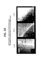
- a basic reactor as shown in FIG. 50 is utilized.
- a conventional basic reactor is of a batch type in which a source gas 01, as a carbon source, is brought into contact with a catalyst 05 placed on a boat 04 within a reaction tube 03 provided with a heating means 02, whereby a carbon nanofiber 06 is grown on the catalyst 05.
- the conventional apparatus as shown in FIG. 50 therefore, has posed the problem that mass production cannot be performed.
- a vapor phase flow process is considered in which a source gas 01 is heated by a heating means 02, while being supplied into a reaction tube 03, to produce a carbon nanofiber.
- the present invention relates to carbon nano-fibrous rods composed of a plurality of hexagonal carbon layers, each of the hexagonal carbon layers having a central axis extending in the same direction.
- the present invention is concerned with fibrous nanocarbon comprising a plurality of the above carbon nanofibrous rods gathered together.
- the present invention relates to a method for producing fibrous nanocarbon comprising an aggregate of carbon nano-fibrous rods by reacting a carbon material in a high temperature fluidized bed with use of a catalyst, characterized by using, as a fluid material, dual-purpose catalyst/fluid materials comprising a metal catalyst-supporting carrier bound via a binder, and characterized by performing a first gas supply step of supplying a reducing gas, a carbon material supply step of supplying the carbon material in a gaseous state to produce a carbon nano-fibrous rod in a presence of the metal catalyst of the dual-purpose catalyst/fluid material, and a second gas supply step of supplying a carbon-free gas to eliminate a fluidizing function of the dual-purpose catalyst/fluid material.
- the present invention relates to the use of an apparatus comprising a fluidized bed reactor charged with dual-purpose catalyst/fluid material, which material comprises a metal-catalyst supporting carrier bound via a binder, and provided with heating means for heating an interior of the fluidized bed reactor; first gas supply means for supplying a reducing gas into the fluidized bed reactor; carbon material supply means for supplying carbon material in a gaseous state into the fluidized bed reactor; second gas supply means for supplying a gas free from carbon into the fluidized bed reactor; and a discharge line for discharging a gas and scattered particles from the fluidized bed reactor, for producing fibrous nanocarbon comprising a plurality of carbon nano-fibrous rods gathered together, wherein said carbon nano-fibrous rods comprise 2 to 12 hexagonal carbon layers being stacked, the hexagonal carbon layers each having a central axis extending in one direction.
- the present invention pertains to an apparatus for producing fibrous nanocarbon comprising a fluidized bed reactor charged with dual-purpose catalyst/fluid material, which material comprises a metal-catalyst supporting carrier bound via a binder, and provided with heating means for heating an interior of the fluidized bed reactor; first gas supply means for supplying a reducing gas into the fluidized bed reactor; carbon material supply means for supplying the carbon material in a gaseous state into the fluidized bed reactor; second gas supply means for supplying a gas free from carbon into the fluidized bed reactor; and a discharge line for discharging a gas and scattered particles from the fluidized bed reactor, characterized in that the apparatus has at least one of the following features (i) and (ii): (i) recovery means for recovering the scattered particles being provided in the discharge line; (ii)a fluidized bed portion of the fluidized bed reactor having a high velocity flow portion and a low velocity flow portion.
- the present invention is concerned with an apparatus for producing fibrous nanocarbon comprising a first fluidized bed reactor charged interiorly with dual-purpose catalyst/fluid material, which material comprises a metal-catalyst supporting carrier bound via a binder, having heating means for heating an interior of the first fluidized bed reactor, and having first gas supply means for supplying a reducing gas into the first fluidized bed reactor; a second fluidized bed reactor having transport means for transporting the fluid material from the first fluidized bed reactor, and having carbon material supply means for supplying the carbon material in a gaseous state into the second fluidized bed reactor; a third fluidized bed reactor having transport means for transporting the fluid material and a reaction product from the second fluidized bed reactor, and having second gas supply means for supplying the gas free from carbon into the third fluidized bed reactor; and a discharge line for discharging a gas and scattered particles from the third fluidized bed reactor.
- Embodiments of the carbon nano-fibrous rod, fibrous nanocarbon, and the method and apparatus for producing fibrous nanocarbon according to the present invention will be described below, but the present invention is not limited to these embodiments.
- the inventors diligently conducted studies, and have found a novel nano-constitutional unit of fibrous nanocarbon (so-called carbon nanofiber). They have defined the fibrous nanocarbon composed of these constitutional units, and have found fibrous nanocarbon of a polygonal cross section showing a very high degree of graphitization, such that the interplanar distance (d 002 ) between hexagonal carbon layers is 0.500 nm or less, simply under manufacturing conditions involving a relatively low temperature of 700°C or lower. They have also found that the constitutional unit of the fibrous nanocarbon is an aggregate of independent carbon nano-fibrous rods.
- the fibrous nanocarbons of the polygonal cross section gather to form fibrous nanocarbon of a polygonal cross section showing a surface area, measured by nitrogen BET, of 200 m 2 or more, for example, when having a fiber width of 100 nm on the average and an aspect ratio on the order of 30.
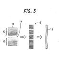
- the hexagonal carbon layer (carbon hexagonal network), the carbon nano-fibrous rod which is a nano-aggregate of the hexagonal carbon layers, and the fibrous nanocarbon which is an array and stack of the carbon nano-fibrous rods will be described based on FIGS. 1(a) and 1(b) and FIGS. 2(a) and 2(b) .
- FIGS. 1(a) and 1(b) are diagrammatic views of a carbon nano-fibrous rod composed of a plurality of hexagonal carbon layers.
- FIGS. 2(a) and 2(b) are schematic views showing a gathered state of carbon nano-fibrous rods.
- a carbon nano-fibrous rod 12 is constituted of hexagonal carbon layers 11 having a central axis extending in one direction.
- the carbon nano-fibrous rod 12 2 to 12 of the hexagonal carbon layers 11 are preferably stacked to form one constitutional unit.
- the number of the hexagonal carbon layers 11 stacked is more preferably 4 to 10.
- the reason why the carbon nano-fibrous rod 12 serves as one unit made up of the stack of 2 to 12 of the hexagonal carbon layers 11 has notbeenelucidatedyet. However, the reason is assumed to be concerned with the crystal lattice structure of a metal catalyst used for synthesis.
- FIG. 1(a) is a diagrammatic view in which 2 of the hexagonal carbon layers 11 form one constitutional unit of the carbon nano-fibrous rod 12.
- FIG. 1(b) is a diagrammatic view in which 8 of the hexagonal carbon layers 11 form one constitutional unit of the carbon nano-fibrous rod 12.
- the hexagonal carbon layer 11 constituting the carbon nano-fibrous rod 12 preferably have an axial width (D) of 2.5 ⁇ 0.5 nm, and an axial length (L) of 17 ⁇ 15 nm.
- a plurality of the carbon nano-fibrous rods 12 are closely packed and stacked to constitute a carbon nano-fibrous rod cluster 13.
- many nano-gaps 14 are present along an axis (in an X-axis direction in FIGS. 2(a), 2(b) ) formed by the carbon nano-fibrous rods 12.
- the nano-gap 14 serves as a space for taking in, for example, atoms such as hydrogen and lithium.
- the presence of the many nano-gaps 14 makes it possible to show the effects of a novel functional material, such as catalytic activity, occlusion or absorption and desorption of a particular substance, and so on.
- the carbon nano-fibrous rods 12 appear to be in contact, but these carbon nano-fibrous rods 12 may be in contact or out of contact. If they do not contact each other, the nano-gaps 14 increase.
- the carbon nano-fibrous rods 12 of a hexagonal cross section gather with a slight clearance.
- a plurality of the carbon nano-fibrous rod clusters 13 composed of the carbon nano-fibrous rods 12 gather three-dimensionally in a fibrous form to form fibrous nanocarbon (so-called carbon nanofiber) 15, as shown in FIG. 3 .
- the carbon nano-fibrous rod 12 has a cross sectional structure in a direction perpendicular to the axis.
- This cross sectional structure is circular in FIG. 2(a) , and hexagonal in FIG. 2(b) , but this is not limitative of the present invention.
- it may be octagonal (see FIG. 4 (c) ) or rectangular such as tetragonal (see FIG. 4(d) ), as well as circular (see FIG. 4(a) ) or hexagonal (see FIG. 4(b) ).
- Representative structures of the fibrous nanocarbon 15 composed of a plurality of the carbon nano-fibrous rod clusters three-dimensionally gathered include, for example, a columnar structure, a feather structure, and a tubular structure (details will be described later).
- the fibrous nanocarbon 15 of a columnar structure will be mainly explained as an example.
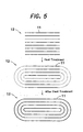
- the carbon nano-fibrous rod 12 according to the present invention is a constitutional unit is not clear in the as-prepared state of the carbon nano-fibrous rod 12, but will become clear by performing heat treatment (or carbonization) at 1, 600°C or higher - after preparation of the carbon nano-fibrous rod 12. That is, the heat treatment at a high temperature of 1, 600°C or higher results in the construction of a carbon network in which the ends in the axial direction of the carbon nano-fibrous rod 12 form a loop two-dimensionally, or a dome three-dimensionally, as shown in FIG. 5 . This makes it clear that the carbon nano-fibrous rod 12 is one constitutional unit.
- the carbon nano-fibrous rod 12, whose ends do not form a loop in the as-prepared state may be described as the "as-prepared state", while the carbon nano-fibrous rod 12, which has been heat-treated at a high temperature of, say, 2,800°C, may be described as the "2,800°C heat-treated state”.
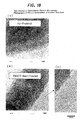
- FIGS. 6 (a) and 6 (b) are photographs of the carbon nano-fibrous rod 12 taken under a high resolution transmission electron microscope, HRTEM).
- FIG. 6(a) is a photograph of an aggregate of the carbon nano-fibrous rods 12 obtained by the method of synthesis to be described later
- FIG. 6(b) is a photograph of an aggregate of the carbon nano-fibrous rods 12 improved in the degree of graphitization by heat treatment at 2,800°C to be described later.
- a size of 10 nm is shown.
- FIGS. 7 (a) and 7 (b) are photographs of the carbon nano-fibrous rod 12 (in the 2, 800°C heat-treated state) taken under an electron microscope.
- FIG. 7 (a) is a high resolution transmission electron microscope (HRTEM) photograph
- FIG. 7(b) is a scanning tunneling electron microscope (STM) photograph. Arrows in the photographs show a size of 20 nm.
- FIGS. 6(a), 6(b) and FIGS. 7(a), 7(b) the stacked state of 6 to 7 of the hexagonal carbon layers 11 is represented, and these layers can be confirmed to constitute the carbon nano-fibrous rod 12. Accordingly, it can be confirmed that the carbon nano-fibrous rod 12 constitutes one constitutional unit, and a gathering of these constitutional units constitutes the fibrous nanocarbon 15.
- the unclearness of the above scanning tunneling electron microscope (STM) photograph is ascribable to a high magnification, and to its principle of photography under which a clearer photograph cannot be obtained at the present time. However, it can be confirmed that the carbon nano-fibrous rod 12 is one constitutional unit.
- FIG. 8 is another scanning tunneling electron microscope (STM) photograph of the carbon nano-fibrous rod 12 (in the 2800°C heat-treated state).
- STM scanning tunneling electron microscope
- FIG. 9 is.a schematic view showing a manner in which the carbon nano-fibrous rods 12 as shown in the right-hand portion of FIG. 8 gather to form a carbon nano-fibrous rod cluster 13.
- the hexagonal carbon layer according to the present embodiment is the same as that in black materials accounting for most of the current carbon materials, and has a hexagonal layer of carbon atoms as the basic unit of its structure.
- the properties of these carbon materials are known to be determined basically by the completeness and size of the hexagonal carbon layer, the thickness of a stack of the hexagonal carbon layers, the regularity of the stack, and the mode and degree of selective orientation of the carbon layer ( Dictionary of Carbon Terminology, p. 226, The Carbon Society of Japan, edited by the Dictionary of Carbon Terminology Edition Committee, Agne Shofu-sha, Tokyo, 2000 ).
- the carbon nano-fibrous rod 12 according to the present invention has hexagonal layers of carbon atoms as basic units, and is established by 95% or more of carbon atoms. When the carbon nano-fibrous rod 12 is heat-treated at a high temperature of 2, 000°C or higher, it is established by 99% or more of carbon atoms.
- the interplanar spacing (d 002 ) of the nano-aggregate of the hexagonal carbon layers 11 of the carbon nano-fibrous rod 12 is less than 0.500 nm, and is similar to the magnitude (0.3354 nm) of the interplanar spacing (d 002 ) of pure graphite.
- the carbon nano-fibrous rod 12 according to the present invention has a high degree of graphitization.
- the fibrous nanocarbon 15 of the columnar structure is produced at 700°C or lower, and the interplanar distance (d 002 ) of its hexagonal carbon layers is less than 0.500 nm, as shown in Table 1 below.
- the fibrous nanocarbon 15 comprises the aforementioned carbon nano-fibrous rods 12 closely packed in a three-dimensional direction.
- the stack shown in FIG. 3 represents a columnar stacked structure, in which a plurality of the carbon nano-fibrous rods 12 are stacked in a first direction (in an up-and-down direction of the sheet face), with their central axes being parallel, to constitute a carbon nano-fibrous rod cluster 13, from which fibrous nanocarbon 15 is formed.
- FIG. 10 is a high resolution transmission electron microscope photograph of the fibrous nanocarbon 15 of a columnar structure heat-treated at 2,800°C. As shown in FIG. 10 , the carbon nano-fibrous rods 12 looped at the front ends are closely packed to constitute the carbon nano-fibrous rod cluster 13 which forms the fibrous nanocarbon 15.
- FIG. 10(a) is an enlarged view (X150,000 magnification) of the fibrous nanocarbon 15.
- FIG. 10 (b) is an enlarged view of opposite end portions (point A and point B in FIG. 10(a) ) in a direction perpendicular to the axial direction (right-and-left direction in FIG. 10(a) ) of the fibrous nanocarbon 15.
- FIG. 10(b) clearly shows that the carbon nano-fibrous rods 12, which have been domed three-dimensionally at the front ends by heat treatment, are closely packed in a three-dimensional direction to constitute carbon nano-fibrous rod clusters 13, thereby forming the fibrous nanocarbon 15.
- the mode of gathering of the carbon nano-fibrous rods 12 is various, and the carbon nano-fibrous rods 12 are stacked or gathered in a direction perpendicular to, identical with, or intersecting, the axes of the carbon nano-fibrous rods 12 to constitute the carbon nano-fibrous rod cluster 13.
- Representative structures of the fibrous nanocarbon 15, which comprises a plurality of the carbon nano-fibrous rod clusters 13 gathered three-dimensionally, are classified, for example, into three forms, a feather structure and a tubular structure as well as the columnar structure. Differences among these structures are not clear, but the shape of the fibrous nanocarbon 15 is assumed to change according to differences in the catalyst and the manufacturing conditions.
- FIGS. 11 (a) to 11 (c) are schematic views of the above three forms of the carbon nano-fibrous rod cluster 13.
- the first form is a form in which the carbon nano-fibrous rods are arranged at an angle ( ⁇ ) of greater than 0 degree but smaller than 20 degrees with respect to an axis (X) perpendicular to an axis (Y) in the stacking direction (fiber axis direction). This is called the columnar fibrous nanocarbon cluster 13A ( FIG. 11(a) ).
- the second form is a form in which the carbon nano-fibrous rods are arranged at an angle ( ⁇ ) of greater than 20 degrees but smaller than 80 degrees with respect to the axis (X) perpendicular to the axis (Y) in the stacking direction (fiber axis direction). This is called the feather-shaped fibrous nanocarbon cluster 13B ( FIG. 11(b) ).
- the feather-shaped fibrous nanocarbon cluster 13B takes a herringbone structure.
- the opposed arrangement of the adjacent rows is due to relationship with the catalyst. Thus, there may be an arrangement in which the adjacent rows are not opposed.
- the third form is a form in which the carbon nano-fibrous rods are arranged at an angle ( ⁇ ) of from 80 degrees to 88 degrees with respect to the axis (X) perpendicular to the axis (Y) in the stacking direction (fiber axis direction). This is called the tubular fibrous nanocarbon cluster 13C ( FIG. 11(c) ).
- FIGS. 12(a) to 12(d) are schematic views of examples of the columnar carbon nano-fibrous rod cluster.
- FIG. 12(a) shows that the carbon nano-fibrous rods 12 are stacked in a direction perpendicular to the axial direction of the carbon nano-fibrous rod 12 to constitute the carbon nano-fibrous rod cluster 13A of the columnar type.
- FIGS. 12 (b) and 12 (c) show a state in which one or more carbon nano-fibrous rod clusters 13A are disposed parallel, and the central axes of the carbon nano-fibrous rods 12 are rendered parallel. That is, in FIG. 12(b) , the parallel disposition is the parallel arrangement of the carbon nano-fibrous rod clusters 13A in two rows. In FIG. 12(c) , the parallel disposition is the parallel arrangement of the carbon nano-fibrous rod clusters 13A in four rows. As shown in FIGS. 12(b) and 12(c) , if the carbon nano-fibrous rod clusters 13A are disposed parallel just beside each other, the directions of the central axes of the carbon nano-fibrous rods 12 are identical.
- the carbon nano-fibrous rods 12 of different axial lengths may be stacked to constitute the carbon nano-fibrous rod cluster 13A, with nano-gaps 14 being formed in stacked portions of the respective carbon nano-fibrous rods 12.
- the carbon nano-fibrous rod cluster 13 of a rectangular tubular form in which the nano-gap 14 is present interiorly in a plane condition (see FIG. 13(a) ) and is surrounded on all sides by the carbon nano-fibrous rods 12.
- the cross sectional shape of the carbon nano-fibrous rod cluster 13 in a direction perpendicular to the fiber axis of the carbon nano-fibrous rod cluster 13 is various, such as a hexagonal shape, an octagonal shape, a tetragonal shape, or a circular shape.
- FIGS. 15(a) to 15(c) are high resolution transmission microscope (HRTEM) photographs of the fibrous nanocarbon 15.
- FIGS. 16(a) to 16(c) are scanning tunneling electron microscope (STM) photographs of the fibrous nanocarbon 15. From these photographs, it is confirmed that the shape of the fibrous nanocarbon 15 structured in three modes, columnar structure, feather structure, and tubular structure, is nearly hexagonal or nearly pentagonal.
- the carbon nano-fibrous rod cluster 13A of the columnar structure has an axial width of the order of 15 to 20 nm.
- the fibrous nanocarbon 15 of the columnar structure which is constructed of the carbon nano-fibrous rod clusters 13A arranged sideways in four rows, can be known to have an axial width of 60 to 80 nm. Consequently, it follows that the fibrous nanocarbon 15 of the columnar structure with an axial width of 200 nm comprises the carbon nano-fibrous rod clusters 13A arranged laterally parallel in at least 10 rows.
- Such fibrous nanocarbon 15 is synthesized by using a pure transition metal, typified by iron (Fe), cobalt (Co) or nickel (Ni), singly or as an alloy, as a catalyst, and bringing carbon monoxide or a hydrocarbon, such as methane (CH 4 ), ethylene (C 2 H 6 ) or propane (C 3 H 8 ), into contact with the catalyst for a certain period of time in a gas mixture with hydrogen (hydrogen partial pressure: 0 to 90%) at a temperature in the range of 400 to 1,200°C.
- a pure transition metal typified by iron (Fe), cobalt (Co) or nickel (Ni), singly or as an alloy
- carbon monoxide or a hydrocarbon such as methane (CH 4 ), ethylene (C 2 H 6 ) or propane (C 3 H 8 )
- a preferred manufacturing example concerned with the production of the fibrous nanocarbon 15 of the columnar structure is as follows:
- the prepared iron catalyst (30 mg) is placed on a quartz boat (length 10 mm, width 2.5 mm, depth 1.5 mm (external values)), and is reduced for 0.5 to 10 hours at 500°C in a quartz tube with an internal diameter of 4.5 cm, with a gas mixture of hydrogen and helium (hydrogen partial pressure: 20%) being flowed therethrough at 100 sccm. Then, the reaction is performed for 0.25 to 3 hours at a temperature of 450 to 620°C, with a gas mixture of carbon monoxide and hydrogen (hydrogen partial pressure: 10-90%) being flowed at 100 to 200 sccm. By so doing, fibrous nanocarbon 15 of a columnar structure is produced in a predetermined amount (2 to 1,500 mg).
- FIGS. 17(a) and 17(b) show an example of feather-structured fibrous nanocarbon in which the carbon nano-fibrous rods 12 are closely packed in a three-dimensional direction so as to have a certain angle with the axis, thereby constituting a carbon nano-fibrous rod cluster 13B.
- the carbon nano-fibrous rod cluster 13B has a herringbone structure in which the carbon nano-fibrous rods 12 are opposed to each other at a predetermined angle.
- the nano-gaps 14 are present or, as shown in FIG. 17(b) , the carbon nano-fibrous rods 12 intersect each other.
- the feather-structured fibrous nanocarbon 15, as stated earlier, is configured such that the carbon nano-fibrous rods 12 are arranged at an angle ( ⁇ ) of greater than 20 degrees but less than 80 degrees with respect to an axis (X) perpendicular to the axis (Y) in the stacking direction (direction of the fiber axis) (see FIG. 11(b) ).
- the carbon nano-fibrous rod 12 of such feather-structured carbon nano-fibrous rod cluster 13B has an axial width of 2.5 ⁇ 0.5 nm and an axial length of 4 ⁇ 2 nm at a stage when the carbon nano-fibrous rod 12 is synthesized. This is because the carbon nano-fibrous rod 12 is at a more acute angle than in the columnar fibrous nanocarbon cluster 13A, so that the axial length L of the carbon nano-fibrous rod 12, which is a constitutional unit, is shorter.
- the hexagonal carbon layers 11 of the carbon nano-fibrous rod 12 of the carbon nano-fibrous rod cluster 13B have an interplanar spacing (d 002 ) therebetween of less than 0.500 nm, which is similar to the magnitude (0.3354 nm) of the interplanar spacing (d 002 ) of pure graphite.
- the carbon nano-fibrous rod 12 has a high degree of graphitization.
- a concrete manufacturing example concerned with the production of the fibrous nanocarbon 15 of the feather structure is as follows:
- the above catalyst is reduced for 0.5 to 10 hours at 500°C, with a gas mixture of hydrogen and helium (hydrogen partial pressure: 20%) being flowed at 100 sccm, by the same method and by means of the same apparatus as in the aforementioned experiments.
- the reaction is performed for 0.25 to 3 hours at a temperature of 450 to 620°C, with a gas mixture of ethylene and hydrogen (hydrogen partial pressure: 10-90%) being flowed at 100 to 200 sccm.
- fibrous nanocarbon 15 of a herringbone structure is produced in a predetermined amount (2 to 5,400 mg).
- FIGS. 19(a) to 19(c) show an example of tubular-structure fibrous nanocarbon 15 in which the carbon nano-fibrous rods 12 are joined together at the opposite ends in the axial direction so as to have a predetermined number of knots in the axial direction, thereby constituting a carbon nano-fibrous rod cluster 13C.
- the carbon nano-fibrous rod cluster 13C of the tubular structure comprises the carbon nano-fibrous rods 12 joined together at opposite end portions in the axial direction.
- the tubular-structure fibrous nanocarbon cluster 13C is configured such that the carbon nano-fibrous rods 12 are arranged at an angle ( ⁇ ) of from 80 degrees to 88 degrees with respect to the axis (X) perpendicular to the axis (Y) in the stacking direction (direction of the fiber axis) (see FIG. 11(c) ).
- the carbon nano-fibrous rod 12 constituting this tubular-structure has an axial width of 2.5 ⁇ 0.5 nm and an axial length of 13 ⁇ 10 nm at a stage when the carbon nano-fibrous rod 12 is synthesized.
- FIG. 19(a) shows the construction of the tubular-structure fibrous nanocarbon cluster 13C from the carbon nano-fibrous rods 12 joined together rectilinearly (in the same row) at axial end portions.
- FIG. 19(b) shows the construction of the tubular-structure fibrous nanocarbon cluster 13C from the carbon nano-fibrous rods 12 joined together such that the axial end portions of the paired carbon nano-fibrous rods 12 sandwich the axial end portion of the single carbon nano-fibrous rod 12.
- FIG. 19 (c) shows the construction of the tubular-structure fibrous nanocarbon cluster 13C from the carbon nano-fibrous rods 12 joined together such that the axial end portions of the carbon nano-fibrous rods 12 overlap.
- the manner of joining is not limited to these manners. Indeed, joining is performed at the opposite end portions of the axis, so that the carbon nano-fibrous rod cluster 13C is formed with the knots.
- the hexagonal carbon layers 11 of the carbon nano-fibrous rod 12 of the carbon nano-fibrous rod cluster 13C have an interplanar spacing (d 002 ) therebetween of less than 0.3400 nm, which is similar to the magnitude (0.3354 nm) of the interplanar spacing (d 002 ) of pure graphite.
- the carbon nano-fibrous rod 12 has a high degree of graphitization.
- a concrete working example concerned with the production of the fibrous nanocarbon 15 of the tubular structure is as follows:
- the fibrous nanocarbon 15 which comprises the carbon nano-fibrous rod cluster 13A of the columnar structure, at a temperature of 1,600°C or higher under vacuum or in an atmosphere of an inert gas.
- the fibrous nanocarbon 15 comprising the carbon nano-fibrous rod cluster 13 according to the present invention, as shown in the aforementioned Table 1, has a high degree of graphitization in the as-prepared state when taking a columnar structure or a tubular structure, and thus possesses adequate properties as an artificial graphite-based highly functional material; if this material is graphitized at 2,000°C or higher, it has a high degree of graphitization when taking any of the structures, including a herringbone structure.
- heat treatment is performed at a temperature of 1,600°C or higher, preferably 2,000°C or higher, more preferably 2,800°C or higher. If the heat treatment temperature is lower than 1,600°C, the degree of graphitization is low.
- the ends of the carbon nano-fibrous rod 12 made of the hexagonal carbon layers 11 in the surface portion of the fibrous nanocarbon 15 are joined in a loop form two-dimensionally, or in a circular or hexagonal domic cross sectional shape three-dimensionally, thereby constituting one unit.
- FIG. 20 shows a schematic drawing of heat treatment of the carbon nano-fibrous rod 12.
- the carbon nano-fibrous rod 12 composed of eight hexagonal carbon layers 11 constitutes one unit.
- the end faces of the carbon nano-fibrous rods 12 comprising the hexagonal carbon layers 11 are joined to form the dome-shaped graphitized carbon nano-fibrous rod cluster 13.
- a plurality of the graphitized carbon nano-fibrous rod clusters 13 are stacked to form the fibrous nanocarbon 15.
- FIGS. 10(a), 10(b) showing the high resolution transmission electron microscope (HRTEM) photographs of the fibrous nanocarbon 15 of the columnar structure before and after graphitization, it can be confirmed that the end faces (edge surfaces) of the hexagonal carbon layers before high-temperature treatment are joined in a loop form two-dimensionally after high-temperature treatment.
- HRTEM transmission electron microscope
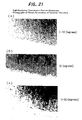
- FIGS. 21(a) to 21(c) are photographs of the carbon nano-fibrous rod cluster 13A constituting the fibrous nanocarbon 15 of the columnar structure, which was treated at a high temperature of 2,800°C, the photographs being taken at varying angles (-30 degrees, 0 degree, +30 degrees) of a transmission electron beam of a high resolution transmission electron microscope.
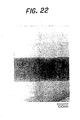
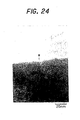
- FIGS. 23 to 25 are photographs (X600,000 magnification) of the fibrous nanocarbon 15 shown in FIG. 22 (X150, 000 magnification), the photographs being taken with the angle of the transmission electron beam of the high resolution transmission electron microscope being varied (-30 degrees ( FIG. 23 ), 0 degree ( FIG. 24 ), +30 degrees ( FIG. 25 )).
- FIGS. 26 to 28 are enlarged photographs (X3, 200, 000 magnification) of FIGS. 23 to 25 , FIG. 26 representing -30 degrees, FIG. 27 representing 0 degree, and FIG. 28 representing +30 degrees.
- FIGS. 29 (a) to 29 (c) arehighresolutionscanning tunneling electron microscope (STM) photographs of three types of fibrous nanocarbons 15 before and after high-temperature heat treatment.
- the (10)-planes comprising the hexagonal carbon layer 11 i.e., 100-plane, 110-plane
- the edge plane cannot be observed at a high magnification.
- the carbon nano-fibrous rod 12 can be observed from all photographs of the three types of fibrous nanocarbons 15 before heat treatment.
- a three-dimensional close-packed stack of the carbon nano-fibrous rods 12 can be confirmed to constitute the fibrous nanocarbon 15.
- FIGS. 30(a) to 30(c) are high resolution transmission electron microscope photographs of the carbon nano-fibrous rod cluster 13A in the as-prepared condition (prepared at 600°C using an iron catalyst) constituting the fibrous nanocarbon 15 of the columnar structure, and structures after treatment at high temperatures of 2,000°C and 2,800°C.
- FIG. 31 shows the Raman scattering spectra, before and after heat treatment, of the fibrous nanocarbon 15 comprising the carbon nano-fibrous rod cluster 13A of the columnar structure. Recent studies have demonstrated that a peak at 1, 350 cm -1 in the Raman scattering spectrum of carbon represents, with high sensitivity, not only the quantitative determination of amorphous carbon, but also the quantitative determination of the edge plane (10-plane) of the hexagonal carbon layer 11.
- the fibrous nanocarbon 15 of the columnar structure before graphitization and that after graphitization are not very different.
- the transmission electron microscope photographs of FIGS. 31 (a) to 31(c) and the Raman spectra of FIG. 32 can confirm that the peak in the vicinity of 1,350 cm -1 is markedly decreased as a result of heat treatment at 2,000°C or higher.
- the fibrous nanocarbon 15 made up of the carbon nano-fibrous rods 12 according to the present invention has a high degree of graphitization when taking a columnar structure or a tubular structure.
- a high conductivity (heat, electricity) filler such as an electrode material of a lithium secondary battery, an electromagnetic wave shielding material, or a catalyst carrier for fuel cells or organic reactions. Since it has a large surface area when taking a feather structure, moreover, it can be expected to be used as an electrode material for supercapacitors, an occluding material for methane and hydrogen, a desulfurizing material for SOx, or a denitrating material for NOx.
- FIG. 32 is a schematic view of a first embodiment of an apparatus for use in producing fibrous nanocarbon.
- an apparatus 100 for producing fibrous nanocarbon is an apparatus for producing fibrous nanocarbon 15 by reacting a carbon material 106 in a high temperature fluidized bed with the use of a catalyst.
- This apparatus 100 comprises a fluidized bed reactor 103 charged with a dual-purpose catalyst/fluid material 101, which comprises a catalyst-supporting carrier bound via a binder, for forming a fluidized bed, and also equipped with a heating means 102 for heating the interior; a first gas supply means 105 for supplying a reducing gas (H 2 , or an inert gas containing H 2 , or CO) 104 into the fluidized bed reactor 103; a carbon material supply means 107 for supplying the carbon material 106, which is brought into contact with the dual-purpose catalyst/fluid material 101 for generating the fibrous nanocarbon 15, in a gaseous state into the fluidized bed reactor 103; a second gas supply means 109 for supplying a carbon-free inert gas 108 into the fluid
- the fluidized bed reactor 103 is formed from a fluidized bed portion 103A forming a fluidized bed, and a free board portion 103B in communication with an upper part of the fluidized bed portion 103A.
- the type of reaction of the fluidized bed includes a bubble fluidized bed type, and a jet fluidized bed type. Either type may be used for the present invention.
- the free board portion 103B preferably has a larger channel sectional area than that of the fluidized bed portion 103A.
- a particle recovery means 112 for recovering the scattered particles 110 is interposed in the gas discharge line 111.
- a means for catching or recovering particles such as a cyclone or a filter, can be named, for example.
- the cyclone separates the scattered particles 110 contained in the gas G by a centrifugal force, and the separated scattered particles 110 containing the fibrous nanocarbon 15 can be recovered from the bottom or the like of the cyclone.
- an ordinary fluid material such as silica sand or alumina
- the dual-purpose catalyst/fluid material 101 is used, as the fluid material forming the fluidized bed.
- the dual-purpose catalyst/fluid material 101 forms the fluidized bed, and the carbon material 106 is supplied to produce the fibrous nanocarbon 15.
- the fluid material 101 is finely divided or treated in other manner to eliminate its function of the fluid material so that the fibrous nanocarbon 15 growing on the catalyst can be easily recovered.
- the dual-purpose catalyst/fluid material 101 (catalyst) is present uniformly in the fluidized bed reactor 103.
- the efficiency of contact of the catalyst with the carbon material 106 is satisfactory, and a uniform reaction can be performed.
- the dual-purpose catalyst/fluid material 101 is divided into fine pieces until converted into its constitutional units or its aggregate units. By this procedure, the efficiency of separation of the fibrous nanocarbon 15 growing on each catalyst can be increased, and the fibrous nanocarbon 15 with uniform properties can be easily obtained.
- FIGS. 33 (a) to 33 (e) are schematic views of the production of a dual-purpose catalyst/fluid material 101, and a process for producing fibrous nanocarbon 15 from a carbon material 106 with the use of the fluid material 101.
- the method for producing the fibrous nanocarbon 15 uses, as a fluid material, the dual-purpose catalyst/fluid material 101 having a carrier 122, which supports a metal catalyst 121 thereon, bound via a binder 123, and includes (1) a first gas supply step of supplying a reducing gas 104, (2) a carbon material supply step of supplying the carbon material 106 in a gaseous state to produce a carbon nano-fibrous rod 15 in the presence of the catalyst 121 of the dual-purpose catalyst/fluid material 101, and (3) a second gas supply step of supplying a carbon-free inert gas 108 to eliminate the fluidizing function of the dual-purpose catalyst/fluid material 101.
- the dual-purpose catalyst/fluid material 101 according to the present invention comprises the carrier 122 supporting the catalyst 121 bound by the binder 123.
- the dual-purpose catalyst/fluid material 101 is shown by its contour alone.
- the fiber diameter of the fibrous nanocarbon 15 can be rendered smaller.
- the fine catalyst 121 can be supported on the carrier 122, for example, by controlling conditions, such as the concentration of the nitrate of the catalyst metal, the type of a surface active agent added, and drying conditions.
- the tiny particle size of the catalyst 121 for support on the carrier 122 is important.
- the fine division gives rise to a particle diameter of 10 nm. If the particle diameter of the catalyst 121 supported initially is 100 nm, the fine division results in a particle diameter of 1 nm.
- the resulting dual-purpose catalyst/fluid material 101 is filled into the fluidized bed reactor 103, and H 2 or an inert gas containing H 2 , as the reducing gas 104, is supplied from first gas supply means 105.
- the supply of the reducing gas 104 such as H 2 converts the catalyst 121 supported on the carrier 122 from the form of nitrate into a metal, and enables the catalyst 121 to perform its function of a catalyst.
- the carbon material 106 is supplied in a gaseous state to grow the fibrous nanocarbon 15 on the catalyst 121.
- the inert gas 108 is separately introduced into the fluidized bed reactor 103 under predetermined flow conditions.
- the carbon material 106 may be any compound containing carbon.
- alkanes such as methane, ethane, propane, and hexane
- unsaturated organic compounds such as ethylene, propylene, and acetylene
- aromatic compounds such as benzene and toluene
- petroleum and coal including coal-converted gas.
- these materials are not restrictive of the present invention.
- the above-mentioned fibrous nanocarbon 15 forms and grows, starting on the catalyst 121 of the dual-purpose catalyst/fluid material 101.
- the reducing gas 104 such as hydrogen (H 2 ) or carbon monoxide (CO)
- the catalyst 121 in the initial stage is of the order of 100 nm
- the catalyst can be broken by fine division to a size on the order of 1 nm.
- the fiber diameter and the fiber structure of the resulting fibrous nanocarbon 15 can be controlled by regulating various conditions, such as the reducing gas 104 and temperature, in each of the above steps (the first gas supply step, the carbon supply step, and the fibrous nanocarbon generation step).
- the inert gas 108 containing no carbon is supplied, as shown in FIG. 33(e) , and the interior of the fluidized bed reactor 103 is raised to a higher temperature than the reaction temperature by heating means 102.
- the binder 123 forming the dual-purpose catalyst/fluid material 101 is decomposed by pyrolysis or the like, to decrease the particle diameter of the fluid material 101 and finely divide the fluid material 101, thereby eliminating its function as a fluid material.
- the fluid material deprived of its fluid function changes into an agglomerate or binding product of the carrier 122, and takes a finely divided form.
- This finely divided material is discharged outside, as scattered particles 110, together with the gas G, through the discharge line 111 via the free board portion 103B of the fluidized bed reactor 103, and is recovered by the particle recovery means 112 (see FIG. 32 ).
- fibrous nanocarbon 15 is separated from the recovered scattered particles 110, whereby fibrous nanocarbon 15 as a product can be obtained.
- the fibrous nanocarbon 15 generated on the catalyst 121 is separated.
- the fibrous nanocarbon 15 can be separated from the catalyst 121 or the carrier 122, for example, by eliminating the catalyst 121 or the carrier 122 at the root portion from which the fibrous nanocarbon 15 grows. An example of this separation is shown in FIG. 34 .
- the carrier 122 or the like at the root portion of the fibrous nanocarbon 15 is eliminated by gasifying the carrier 122 or the like at the root portion of the fibrous nanocarbon 15 with H 2 , or supplying steam (H 2 O) or CO 2 as a gasifying agent, or by controlling the temperature for promotion of gasification.
- the fibrous nanocarbon 15 growing from the catalyst 121 can be separated from the catalyst 122, or the unused catalyst 121 remaining on the catalyst 122. Such separation can be carried out at least either after recovery from the fluidized bed reactor 103, or during the production within the fluidized bed reactor 103.
- the dual-purpose catalyst/fluid material 101 has an average particle diameter of 0.2 to 20 nm so as to be able to perform a satisfactory flowing function within the fluidized bed reactor 103. This is because by setting the average particle diameter of the dual-purpose catalyst/fluid material 101 in the above range, the dual-purpose catalyst/fluid material 101 can be stirred vigorously within the fluidized bed reactor 103, with the result that a uniform site of reaction can be formed.
- the dual-purpose catalyst/fluid material 101 can be prepared by a publicly known granulation method (for example, a self-sufficient granulation method such as rotating pan type granulation, rotating drum type granulation, or fluidized bed type granulation, or a forced granulation method such as compression type granulation or extrusion type granulation).
- a publicly known granulation method for example, a self-sufficient granulation method such as rotating pan type granulation, rotating drum type granulation, or fluidized bed type granulation, or a forced granulation method such as compression type granulation or extrusion type granulation.
- the flow velocity within the fluidized bed reactor 103 is preferably 0.02 to 0.2 m/s, if the particle diameter of the dual-purpose catalyst/fluid material 101 is 0.2 mm. This is because, as shown in FIGS. 35 and 36 , if the flow velocity is less than 0.02 m/s, the fluidization of the dual-purpose catalyst/fluid material 101 does not occur, and the dual-purpose catalyst/fluid material 101 does not function as a fluidized bed. If the flow velocity exceeds 0.2 m/s, the fluidmaterial 101 scatters outside of the fluidized bed reactor 103, and the reaction time cannot be controlled. These events are undesirable.
- the superficial velocity of the fluidized bed may be set by selecting different optimum values from within the range of 2 to 8 times the fluidization start velocity (Umf) of a fluid medium used, depending on the conditions such as the raw material, additive, etc. used. That is, the superficial velocity is set at a gas flow velocity 2 to 8' times as high as the fluidization start velocity. This superficial velocity is maintained constantly at the selected optimum value, mainly, by controlling the amount of gas supplied from the inert gas supply means.
- the temperature of the contact reaction between the catalyst 121 of the dual-purpose catalyst/fluid material 101 and the carbon material 106 is preferably 300 to 1,300°C, and the pressure is preferably 0.1 to 25 atmospheres. This is because if the above temperature and pressure are outside the above ranges, a satisfactory fibrous nanocarbon 15 cannot be produced.
- the carbon material 106 is brought into contact with the catalyst 121 of the dual-purpose catalyst/fluid material 101 for a certain period of time in the reducing gas 104 under a hydrogen partial pressure of 0 to 90%, whereby the fibrous nanocarbon 15 is obtained.
- the supply of H 2 in this reaction is intended for promoting the growth of the fibrous nanocarbon 15 on the catalyst 121 of the dual-purpose catalyst/fluid material 101.
- hydrogen in the carbon material 106 supplied can be utilized as a source of H 2 .
- the conditions such as temperature, pressure, time, and gas atmosphere, may be controlled independently of each other.
- the temperature may be rendered lower than in the manufacturing conditions for the fibrous nanocarbon 15 in the carbon material supply step.
- the dual-purpose catalyst/fluid material 101 is composed of a product formed by supporting the catalyst 121 on the surface of the carrier 122, or an agglomerate of the products, as shown in FIG. 33(a) .
- This carrier 122 has a particle diameter of the order of 40 nm, but this is not restrictive.
- the agglomerate refers to a material formed from several of the carriers 122 self-agglomerated to an average particle diameter of the order of 100 to 200 nm.
- the material for the carrier 122 includes, for example, carbon black (CB), alumina (Al 2 O 3 ), silica (Si), silica sand (SiO 2 ), and aluminosilicate.
- CB carbon black
- Al 2 O 3 alumina
- Si silica
- SiO 2 silica sand
- aluminosilicate aluminosilicate
- the above carrier 122 preferably has an average particle diameter of 200 ⁇ m or less.
- the carrier 122 having the catalyst 121 supported on the surface, or the agglomerate of the carriers 122 is formed into a binding product by use of the binder 123, whereby the dual-purpose catalyst/fluid material 101 having an average particle diameter of 0.2 to 20 mm is prepared.
- the catalyst 121 includes, for example, Fe, Ni, Co, Cu and Mo, or a mixture of at least two of these metals, but the present invention is not limited to them.
- Fe is used as the catalyst 121 and carbon black is used as the carrier 122, it is recommendable to charge carbon black into an aqueous solution of iron nitrate or iron acetate, thereby supporting Fe on the surface of carbon black.
- the catalyst 121 is supported on the surface 122a or in pores 122b of the carrier 122, as indicated in the enlarged view of FIG. 33(a) .
- a polymer-based adhesive, an inorganic adhesive, or other material having a binding action, for example, can be named as the above binder 123.
- a binder comprising a thermosetting polymeric material, such as phenolic resin (maximum operating temperature: ⁇ 360°C), urea resin (maximum operating temperature: ⁇ 288°C), epoxy resin (maximum operating temperature: ⁇ 288°C), or polyimide resin (maximum operating temperature: ⁇ 349°C).
- phenolic resin maximum operating temperature: ⁇ 360°C
- urea resin maximum operating temperature: ⁇ 288°C
- epoxy resin maximum operating temperature: ⁇ 288°C
- polyimide resin maximum operating temperature: ⁇ 349°C
- SiO 2 and Al 2 O 3 can be named as the inorganic adhesive, but the present invention is not limited to them.
- Tars and heavy oil for example, can be named as other binding materials having a binding action, but the present invention is not limited to them.
- fibrous nanocarbon 15 is produced at a temperature on the order of 480°C, and then the inert gas 108 containing no carbon is supplied.
- the system is heated in a stroke to about 800°C by the heating means 102 to decompose the binder 123 thermally and finely divide the dual-purpose catalyst/fluid material 101 until it is restored to the carrier 122.
- Thermal decomposition is considered to proceed to some degree under the 480°C conditions, but actually caulking as well as thermal decomposition takes place under the oxygen-free conditions, and sintering of carbon may proceed. In this case, as stated earlier, it is recommendable to perform gasification with H 2 at 800°C or higher, or burning in an environment where fibrous nanocarbon 15 is not burned.
- the tars can be gasified and removed using H 2 or CO at a temperature of 800°C or higher.
- FIG. 37 is a diagrammatic view of a second embodiment of the apparatus for use in producing fibrous nanocarbon.
- an apparatus 200 for producing fibrous nanocarbon according to the present embodiment is the apparatus of FIG. 1 modified so that the fluid material 101 can become fluid continuously. That is, the interior of the fluidized bed portion 103A of the fluidized bed reactor 103 is divided into three parts to form a first flow chamber 203A-1, a second flow chamber 203A-2, and a third flow chamber 203A-3.
- the first flow chamber 203A-1 is provided with a first gas supply means 105 for supplying a reducing gas 104
- the second flow chamber 203A-2 is provided with a carbon material supply means 107 for supplying a carbon material 106
- the third flow chamber 203A-3 is provided with a second gas supply means 109 for supplying a carbon-free inert gas 108.
- a plurality of partition plates 202 are provided within the fluidized bed reactor 103 in such a manner as to suspend downward and rise upward alternately in a vertical axis direction, thereby dividing the interior while forming a fluidized bed.
- a first room 203A-11, a second room 203A-12 and a third room 203A-13 are located in this order from the left to constitute the first flow chamber 201A-1
- a fourth room 203A-24, a fifth room 203A-25, a sixth room 203A-26 and a seventh room 203A-27 are located in this order to constitute the second flow chamber 203A-2
- an eighth room 203A-38 and a ninth room 203A-39 are located in this order to constitute the third flow chamber 203A-3.
- the free board portion 103B is common to the first, second and third flow chambers.
- a fluid material supply means 204 for supplying a dual-purpose catalyst/fluid material 101 to the first flow chamber 203A-1 is provided to supply the dual-purpose catalyst/fluid material 101 successively.
- the positions of the partition plates 202 and the capacities of the respective chambers are adjusted so that 7 hours of dwelling in the first flow chamber 203A-1, 1 hour of dwelling in the second flow chamber 203A-2, and 1 hour of dwelling in the third flow chamber 203A-3 can be carried out.
- the dual-purpose catalyst/fluid material 101 can be made to dwell in each chamber for an arbitrary period of time.
- the reducing gas 106 is supplied to perform the catalytic function of the dual-purpose catalyst/fluid material 101.
- the carbon material gas 106 is supplied and brought into contact with the dual-purpose catalyst/fluid material 101 performing the catalytic function to produce fibrous nanocarbon 15 with good efficiency.
- the carbon-free inert gas 108 is supplied and a higher temperature than the reaction temperature is achieved to eliminate the catalytic function of the dual-purpose catalyst/fluid material 101 and finely divide this material 101, thereby scattering it as scattered particles 110 with a particle diameter of 40 to 100 nm, along with a gas G, for the purpose of recovery.
- the dual-purpose catalyst/fluid material 101 which does not scatter, is separately recovered by a recovery means.
- a fluidized bed reactor having a fluidized bed portion constituted from the first flow chamber and the second flow chamber, and a fluidized bed reactor having a fluidized bed portion constituted from the third flow chamber.
- FIG. 38 is a schematic view of a third embodiment of the apparatus for producing fibrous nanocarbon.
- fluidized bed reactors 103 are configured as having independent functions, thus making continuous production possible.
- an apparatus 300 for producing fibrous nanocarbon is an apparatus for producing fibrous nanocarbon 15 by reacting a carbon material 106 in high temperature fluidized beds with the use of a catalyst.
- This apparatus 300 comprises a first fluidized bed reactor 301 charged with a dual-purpose catalyst/fluid material 101, equipped with a heating means 102 for heating the interior, and having a first gas supply means 105 for supplying a reducing gas (H 2 or CO) 104; a second fluidized bed reactor 303 having a transport means 302 for transporting the dual-purpose catalyst/fluid material 101 from the first fluidized bed reactor 301, and also having a carbon material supply means 107 for supplying the carbon material 106, which is brought into contact with the dual-purpose catalyst/fluid material 101 for generating the fibrous nanocarbon 15, in a gaseous state into the fluidized bed reactor 303; a third fluidized bed reactor 305 having a transport means 304 for transporting a reaction product and the fluid material from the second
- the reducing gas 106 is supplied to perform the catalytic function of the dual-purpose catalyst/fluid material 101. Then, the dual-purpose catalyst/fluid material 101 is supplied to the second fluidized bed reactor 303 by the transport means 302 using airflow transport or the like. In the second fluidized bed reactor 303, the carbon material gas 106 is supplied and brought into contact with the dual-purpose catalyst/fluid material 101 performing the catalytic function to produce fibrous nanocarbon 15 with good efficiency. Then, the dual-purpose catalyst/fluid material 101 is supplied to the third fluidized bed reactor 305 by the transport means 304 using airflow transport or the like.
- the carbon-free inert gas 108 is supplied and a higher temperature than the reaction temperature is achieved to eliminate the catalytic function of the dual-purpose catalyst/fluid material 101 and finely divide this material 101, thereby scattering it as scattered particles 110 with a particle diameter of 40 to 100 nm, along with a gas G, for the purpose of recovery.
- fibrous nanocarbon 15 can be produced continuously.
- the dual-purpose catalyst/fluid material 101, which does not scatter, is separately recovered by a recovery means.
- transport means 302 and 304 not only means using the above-mentioned airflow transport or the like, but also means relying on feeding transport using a feeder can be named. However, these means are not restrictive, and any means capable of transporting the fluid material 101 or the like can be employed.
- the volumes inside the reactors 301, 303 and 305 may be changed according to the dwell time of the fluid material 101 within the reactors 301, 303 and 305. For example, if the average dwell time is set to be 7 hours for the first fluidized bed reactor 301 and 1 hour for each of the second fluidized bed reactor 303 and the third fluidized bed reactor 305, the volume of the first fluidized bed reactor 301 is set at 7 times the volume of each of the second and third fluidized bed reactors 303, 305, whereby the reaction conditions can be adjusted.
- first to third fluidized bed reactors 301, 303, 305 can be configured to have the same volume, and 7 of the first fluidized bed reactors 301 can be connected together in series.
- a plurality of the first fluidized bed reactors 301 can be provided, where necessary, to adjust the throughput.
- a plurality of the second fluidized bed reactors 303 can be provided, where necessary, to adjust the throughput.
- a plurality of the third fluidized bed reactors 305 can be provided, where necessary, to adjust the throughput.
- FIG. 39 is a schematic view of a fourth embodiment of the apparatus for producing fibrous nanocarbon. As shown in FIG. 39 , the present embodiment is the third embodiment in which two of the second fluidized bed reactors 303 are provided to permit production under different reaction conditions.
- an apparatus 400 for producing fibrous nanocarbon is an apparatus for producing fibrous nanocarbon 15 by reacting a carbon material 106 in high temperature fluidized beds with the use of a catalyst.
- This apparatus 400 comprises a first fluidized bed reactor 301 charged with a dual-purpose catalyst/fluid material 101, equipped with a heating means 102 for heating the interior, and having a first gas supply means 105 for supplying a reducing gas (H 2 or CO) 104 inside; a first-stage second fluidized bed reactor 403-1 having a transport means 402-1 for transporting the dual-purpose catalyst/fluid material 101 from the first fluidized bed reactor 301, and also having a carbon material supply means 107 for supplying the carbon material 106, which is brought into contact with the dual-purpose catalyst/fluid material 101 for generating the fibrous nanocarbon 15, in a gaseous state into the interior; a second-stage second fluidized bed reactor 403-2 having a transport means 402-2 for transporting the dual-purpose catalyst/flui
- the temperature conditions of the heating means 102 of the second-stage second fluidized bed reactor 403-2 are changed (for example, the temperature is rendered 100°C higher) in comparison with the temperature conditions of the heating means 102 of the first-stage second fluidized bed reactor 403-1.
- the reaction temperature is made 480°C within the first-stage second fluidized bed reactor 403-1, for example, whereby a carbon nano-fibrous rod cluster 13B of a feather structure is grown on the catalyst 121 of the dual-purpose catalyst/fluid material 101 (see FIG. 40 ).
- reaction temperature is made 630°C within the second-stage second fluidized bed reactor 403-2, whereby a composite comprising a carbon nano-fibrous rod cluster 13A of a tubular structure grown below the carbon nano-fibrous rod cluster 13B of the feather structure can be produced (see FIG. 41 ).
- FIG. 42 is a diagrammatic view of a fifth embodiment of the apparatus for producing fibrous nanocarbon.
- a fluidized bed portion 103A of a fluidized bed reactor 103 is constructed of a high-velocity side fluidized bed portion 503A-1 and a low-velocity side fluidized bed portion 503A-2.
- a dual-purpose catalyst/fluid material 101 is vigorously stirred within the high-velocity side fluidized bed portion 503A-1 to promote the fine division of the fluid material 101 due to wear and the fine division of the fluidmaterial 101 due to a decrease in the binding force of the binder 123.
- the particle diameter of the dual-purpose catalyst/fluid material 101 is set at 0.5 mm, for example, the flow velocity in the upper low-velocity side fluidized bed portion 503A-2 of the fluidized bed portion 103A is controlled to a value of the order of 0.1 m/s for prevention of scattering, while the flow velocity in the lower high-velocity side fluidized bed portion 503A-1 of the fluidized bed portion 103A is set to be a value of the order of 0.2 to 1.0 m/s, whereby the dual-purpose catalyst/fluid material 101 is vigorously stirred to achieve the fine division of the fluid material 101 due to wear.
- a collision member 501 can be disposed within the high-velocity side fluidized bed portion 503A-1, and the dual-purpose catalyst/fluid material 101 is forcibly caused to collide with the collision member 501 to promote the fine division further.
- FIG. 44 is a diagrammatic view of a sixth embodiment of the apparatus for producing fibrous nanocarbon.
- a high velocity gas blowing means 602 is provided for blowing a high velocity gas 601 into a fluidized bed reactor 103 through a side wall of the reactor 103.
- a dual-purpose catalyst/fluid material 101 is vigorously stirred by the high velocity gas 601 blown in, thereby promoting the fine division of the fluid material 101 due to wear and the fine division of the fluid material 101 due to a decrease in the binding force of the binder 123.
- an N 2 gas or an inert gas as the high velocity gas 601 is blown in from the high velocity gas blowing means 602 at a flow velocity of 10 m/s, whereby the dual-purpose catalyst/fluid material 101 is vigorously stirred to achieve the fine division of the fluid material 101 due to wear.
- the fifth and sixth embodiments are designed to form a high flow velocity zone locally in the dual-purpose catalyst/fluid material 101 within the fluidized bed reactor 103 in the second gas supply step.
- This procedure results in a mutual collision of the fluid material 101, and a collision between the fluid material 101 and the wall surface of the reactor 103 or the collision member 503.
- blowing-in of the high velocity gas 601 is carried out.
- fine division of the dual-purpose catalyst/fluid material 101 due to wear and breakage is promoted to increase the efficiency of recovery of the fibrous nanocarbon 15.
- the resulting fibrous nanocarbon 15 is preferably used for various composite materials, gas adsorbing materials, and bio-materials, such as transparent conductive materials (conductive ink, conductive film, conductive plastic), ITO substitutes, transparent electromagnetic wave shielding materials, antistatic materials (solar cell, mirror, etc.), transparent ultraviolet ray shielding materials (for example, for cosmetic use, for vehicle glass coating use, etc.), high grade electric/heat conductive materials (rolls of printer, facsimile, etc.), high grade electrically conductive and heat dissipating devices, ceramic mixing materials, carbon/carbon composites, conductive materials of batteries, gas adsorbing or occluding materials for methane, etc., hydrogen occluding materials, hydrogen separating materials, separators for butane, capacitor electrode materials, electric demineralization electrode materials, seawater decomposing (electrolytic cell) oxygen electrodematerials, batterymaterials (lithium secondary battery, NaS battery, air secondary battery, and long life alkaline battery conductive materials),
- the dual-purpose catalyst/fluid material comprising the metal catalyst-supporting carrier bound via the binder is used as a fluidmaterial, and there are provided the first gas supply step of supplying the reducing gas, the carbon material supply step of supplying the carbon material in a gaseous state to produce a carbon nano-fibrous rod in the presence of the catalyst of the dual-purpose catalyst/fluid material, and the second gas supply step of supplying the carbon-free inert gas to eliminate the fluidizing function of the dual-purpose catalyst/fluid material.
- the catalyst is uniformly present in the fluidized bed. As a result, the efficiency of contact of the catalyst with the raw material is satisfactory, and a uniform reaction can be performed.
- the fluid material concurrently serving the catalytic function is divided into fine pieces until converted into its constitutional units or its aggregates.
- Example 1 is fibrous nanocarbon of a columnar structure.
- An iron catalyst was prepared by the precipitation method ( Best, R.J., Russell, W.W., J. Amer. Soc. 76, 838(1954 ), Sinfelt, J.H., Carter, J.L., and Yates, D.J.C., J. Catal. 24, 283(1972 )) with the use of iron nitrate.
- iron nitrate FeNO 3 ⁇ 9H 2 O: a first class grade chemical, Wako Pure Chemical Industries
- iron nitrate FeNO 3 ⁇ 9H 2 O: a first class grade chemical, Wako Pure Chemical Industries
- NH 4 HCO 3 a first class grade chemical, Junsei Yakuhin Kogyo
- the precipitate was filtered off, and purified with pure water until ammonium hydrogen carbonate vanished.
- the purified precipitate was vacuumdried (for 8 hours at 80°C), and then heat-treated (for 5 hours at 450°C) in an air atmosphere with the use of a horizontal Tanmann-furnace to obtain Fe 2 O 3 .
- the resulting Fe 2 O 3 was placed on an alumina boat (length 10 mm, width 2.5 mm, depth 1.5 mm (external values)), and was reduced (for 48 hours at 480°C) in an alumina tube (internal diameter 10 cm), with a gas mixture of hydrogen and helium (hydrogen partial pressure: 10%) being flowed therethrough at 100 sccm, thereby obtaining 4.02 g of an iron catalyst.
- the present example is an example in which the fibrous nanocarbon of Example 1 was heat-treated at a high temperature.
- Example 1 the fibrous nonocarbon prepared in Example 1 was heated-treated for 10 minutes at 2,000°C and 2,800°C in an argon atmosphere.
- the present example is fibrous nanocarbon of a feather structure.
- a nickel catalyst was prepared by the precipitation method of Example 1 with the use of nickel nitrate.
- NiNO 3 ⁇ xH 2 O a first class grade chemical, Wako Pure Chemical Industries
- nickel nitrate NiNO 3 ⁇ xH 2 O: a first class grade chemical, Wako Pure Chemical Industries
- NH 4 HCO 3 a first class grade chemical, Junsei Yakuhin Kogyo
- the precipitate was filtered off, and purified with pure water until ammonium hydrogen carbonate vanished.
- the purified precipitate was vacuumdried (for 8 hours at 80°C), and then heat-treated (for 5 hours at 450°C) in an air atmosphere with the use of a horizontal Tanmann-furnace to obtain nickel oxide.
- the resulting nickel oxide was placed on an alumina boat (length 10 mm, width 2.5 mm, depth 1.5 mm (external values)), and was reduced (for 48 hours at 480°C) in an alumina tube (internal diameter 10 cm), with a gas mixture of hydrogen and helium (hydrogen partial pressure: 10%) being flowed therethrough at 100 sccm, thereby obtaining 4.01 g of an iron catalyst.
- the nickel catalyst prepared by the above-described method was placed on a quartz boat (length 10 mm, width 2.5 mm, depth 1.5 mm (external values)), and was reduced (for 2 hours at 500°C) in a quartz tube (internal diameter 4.5 cm), with a gas mixture of hydrogen and helium (hydrogen partial pressure: 20%) being flowed therethrough at 100 sccm. Then, the reaction was performed (for 60 minutes at 580°C), with a gas mixture of ethylene and hydrogen (hydrogen partial pressure: 20%) being flowed at 100 sccm. By so doing, fibrous nanocarbon was produced in a predetermined amount (60 mg).
- the present example is an example in which the fibrous nanocarbon of Example 3 was heat-treated at a high temperature.
- Example 3 the fibrous nonocarbon prepared in Example 3 was heated-treated for 10 minutes at 2,000°C and 2,800°C in an argon atmosphere.
- the present example is fibrous nanocarbon of a tubular structure.
- a iron-nickel alloy catalyst was prepared by the precipitation method of Example 1 with the use of iron nitrate and nickel nitrate.
- NiNO 3 ⁇ xH 2 O a first class grade chemical, Wako Pure Chemical Industries
- iron nitrate FeNO 3 ⁇ 9H 2 O: a first class grade chemical, Wako Pure Chemical Industries
- the precipitate was filtered off, and purified with pure water until ammonium hydrogen carbonate vanished. Then, the precipitate was filtered off, and purified with pure water until ammonium hydrogen carbonate vanished.
- the purified precipitate was vacuum dried (for 8 hours at 80°C), and then heat-treated (for 5 hours at 450°C) in an air atmosphere with the use of a horizontal Tanmann-furnace to obtain iron-nickel oxide.
- the resulting iron-nickel oxide was placed on an alumina boat (length 10 mm, width 2.5 mm, depth 1.5 mm (external values)), and was reduced (for 48 hours at 480°C) in an alumina tube (internal diameter 10 cm) , with a gas mixture of hydrogen and helium (hydrogen partial pressure: 10%) being flowed therethrough at 100 sccm, thereby obtaining 4.05 g of an iron-nickel catalyst.
- the iron-nickel catalyst prepared by the above-described method was placed on a quartz boat (length 10 mm, width 2. 5 mm, depth 1. 5 mm (external values)), and was reduced (for 2 hours at 500°C) in a quartz tube (internal diameter 4.5 cm), with a gas mixture of hydrogen and helium (hydrogen partial pressure: 20%) being flowed therethrough at 100 sccm. Then, the reaction was performed (for 60 minutes at 630°C), with a gas mixture of carbon monoxide and hydrogen (hydrogen partial pressure: 80%) being flowed at 200 sccm. By so doing, fibrous nanocarbon was produced in a predetermined amount (432 mg).
- the present example is an example in which the fibrous nanocarbon of Example 5 was heat-treated at a high temperature.
- the fibrous nonocarbon prepared in Example 5 was heated-treated for 10 minutes at 2,000°C and 2,800°C in an argon atmosphere.
- the fibrous nanocarbons (150 mg) obtained in Examples 1 to 6 were each mixed with 15 mg of standard silicon, and diffraction at angles of 5° to 90° was performed (CuK ⁇ rays, 40 kV, 30 mA, stepwise method) using a wide angle X-ray diffractometer (a product of Rigaku), whereby diffraction patterns were obtained.
- the fibrous nanocarbon was observed under an electric field scanning transmission electron microscope (JEM-2010F).
- a trace amount of the fibrous nanocarbon obtained in each of Examples 1 to 4 was placed in n-butanol, and completely dispersed by ultrasonic dispersion until a pale transparent color appeared.
- One or two drops of the resulting dispersion were added to a fine net sample cell, and the sample cell was dried for a day in air at the ordinary temperature, and then observed.
- FIGS. 6(a), 6(b) Examples 1, 2
- FIGS. 18(a) to 18(c) Examples 3, 4
- FIGS. 6(a) and 6(b) are enlarged (to 8 times) photographs of images observed at 400,000X magnification.
- FIGS. 18 (a) and 18 (b) are photographs of images observed at 400, 000X magnification
- FIG. 18(c) is a photograph further enlarged 8 times (3,200,000X magnification).
- the fibrous nanocarbon obtained in each of Examples 1 to 6 was observed under a scanning tunneling electron microscope (Nanoscope III (DI, U.S.A.).
- a trace amount of the fibrous nanocarbon obtained in each of Examples 1 to 6 was placed in ethanol, and completely dispersed ultrasonically.
- One drop of the resulting dispersion were added to HOPG, dried for 8 hours in air, and observed (tunneling voltage 1V, tunneling current 3.0 nA).
- FIGS. 30(a) to 30(c) Examples 1, 2), FIG. 7(b) (Example 2), FIGS. 15(a) to 15(c) (Examples 1 to 6), and FIGS. 29(a) to 29(c) (Examples 1 to 6).
- FIG. 30 (a) is a photograph in which the fibrous nanocarbon of Example 1 was observed
- FIGS. 30(b) and 30(c) are photographs in which the fibrous nanocarbon of Example 2 was observed.
- FIG. 7 (b) is a photograph in which the fibrous nanocarbon was observed at an angle different from the angle in FIG. 30(c) .
- FIGS. 15(a) to 15(c) are photographs of the fibrous nanocarbons observed at low magnification.
- FIGS. 29(a) to 29(c) are photographs of the fibrous nanocarbons observed at high magnification.
- the iron catalyst (50 mg) prepared by the precipitation method of the aforementioned Example 1 was placed on a quartz boat (length 10 mm, width 2.5 mm, depth 1.5 mm (external values)), and was reduced for 0.3 hour at 500°C in a quartz tube (internal diameter 4.5 cm), with a gas mixture of hydrogen and helium (hydrogen partial pressure: 20%) being flowed therethrough at 100 sccm. Then, the reaction was performed for 60 minutes at a temperature of 580°C, with a gas mixture of carbon monoxide and hydrogen (hydrogen partial pressure: 20%) being flowed at 100 sccm. However, fibrous nanocarbon was not produced.
- the iron catalyst (50 mg) prepared by the precipitation method of the aforementioned Example 1 was placed on a quartz boat (length 10 mm, width 2.5 mm, depth 1.5 mm (external values)), and was reduced for 2 hours at 500°C in a quartz tube (internal diameter 4.5 cm), with a gas mixture of hydrogen and helium (hydrogen partial pressure: 20%) being flowed therethrough at 100 sccm. Then, the reaction was performed for 60 minutes at a temperature of 580°C, with a carbon monoxide gas being flowed at 100 sccm. However, fibrous nanocarbon was not produced.
- the nickel catalyst (50 mg) prepared by the precipitation method of the aforementioned Example 1 was placed on a quartz boat (length 10 mm, width 2.5 mm, depth 1.5 mm (external values)), and was reduced for 2 hours at 500°C in a quartz tube (internal diameter 4.5 cm), with a gas mixture of hydrogen and helium (hydrogen partial pressure: 20%) being flowed therethrough at 100 sccm. Then, the reaction was performed for 60 minutes at a temperature of 580°C, with a gas mixture of carbon monoxide and hydrogen (hydrogen partial pressure: 20%) being flowed at 100 sccm. However, fibrous nanocarbon was not produced.
- the nickel catalyst (50 mg) prepared by the precipitation method of the aforementioned Example 1 was placed on a quartz boat (length 10 mm, width 2.5 mm, depth 1.5 mm (external values)), and was reduced for 2 hours at 450°C in a quartz tube (internal diameter 4.5 cm), with a gas mixture of hydrogen and helium (hydrogen partial pressure: 20%) being flowed therethrough at 100 sccm. Then, the reaction was performed for 60 minutes at a temperature of 580°C, with a gas mixture of carbon monoxide and hydrogen (hydrogen partial pressure: 20%) being flowed at 100 sccm. However, fibrous nanocarbon was not produced.
- the nickel catalyst (50 mg) prepared by the precipitation method of the aforementioned Example 1 was placed on a quartz boat (length 10 mm, width 2.5 mm, depth 1.5 mm (external values)), and was reduced for 2 hours at 500°C in a quartz tube (internal diameter 4.5 cm), with a gas mixture of hydrogen and helium (hydrogen partial pressure: 20%) being flowed therethrough at 100 sccm. Then, the reaction was performed for 60 minutes at a temperature of 680°C, with a gas mixture of carbon monoxide and hydrogen (hydrogen partial pressure: 20%) being flowed at 100 sccm. However, fibrous nanocarbon was not produced.
- the iron-nickel catalyst (50 mg) prepared by the method of the aforementioned Example 5 was placed on a quartz boat (length 10 mm, width 2.5 mm, depth 1.5 mm (external values)), and was reduced for 2 hours at 500°C in a quartz tube (internal diameter 4.5cm), with a gas mixture of hydrogen and helium (hydrogen partial pressure: 20%) being flowed therethrough at 100 sccm. Then, the reaction was performed for 60 minutes at a temperature of 700°C, with a gas mixture of carbon monoxide and hydrogen (hydrogen partial pressure: 20%) being flowed at 200 sccm. As a result, nanocarbon was obtained in a predetermined amount (20 mg). When the nanocarbon was observed under a transmission electron microscope, however, a fibrous structure was not seen. «Method and apparatus for producing fibrous nanocarbon»
- the catalyst (5%) was supported on the carrier.
- a polymer-based adhesive (maximum operating temperature: ⁇ 360°C) formed from a phenolic resin was used as a binder to granulate a dual-purpose catalyst/fluid material.
- fibrous nanocarbon was produced by means of the apparatus of the first embodiment shown in FIG. 32 .
- H 2 /He (20/80) was used for the activation of the catalyst by the first gas supply, and pretreatment was performed for 7 hours. Then, ethylene (C 2 H 4 ) was used as a carbon material, and C 2 H 4 /H 2 (4/1) was supplied. Under these conditions, the reaction was carried out for 1 hour within a fluidized bed reactor at 480°C to produce fibrous nanocarbon. After production of fibrous nanocarbon, the temperature was raised in an atmosphere of H 2 /He (20/80) to decompose the binder thermally, converting the dual-purpose catalyst/fluid material into fine particles, and scattering them for recovery by recovery means.
- FIGS. 46(a) and 46(b) Microphotographs of the resulting fibrous nanocarbon are shown in FIGS. 46(a) and 46(b).
- FIG. 46(a) is the photograph at X10, 000 magnification, the scale being 1 ⁇ m.
- FIG. 46(b) is the photograph at X100,000 magnification, the scale being 1 nm.
- Fibrous nanocarbon was produced by the same procedure as that in Example 1, except that Ni-Mo (2/8) was used as the catalyst, titanium oxide (TiO 2 ) was used as the carrier, and the reaction temperature was 560°C.
- FIGS. 47(a) and 47(b) Photomicrographs of the resulting fibrous nanocarbon are shown in FIGS. 47(a) and 47(b).
- FIG. 47 (a) is the photograph at X10,000 magnification, the scale being 1 ⁇ m.
- FIG. 47(b) is the photograph at X50,000 magnification, the scale being 100 nm.
- Fibrous nanocarbon was produced by the same procedure as that in Example 1, except that Fe-Ni (8/2) was used as the catalyst.
- FIGS. 48(a) and 48(b) Photomicrographs of the resulting fibrous nanocarbon are shown in FIGS. 48(a) and 48(b).
- FIG. 48 (a) is the photograph at X10,000 magnification, the scale being 1 ⁇ m.
- FIG. 48(b) is the photograph at X100,000 magnification, the scale being 1 nm.
- the carbon nano-fibrous rod and fibrous nanocarbon according to the present invention have a high degree of graphitization and a large surface area. Thus, they are preferred for use as highly functional materials (resin, metal, ceramic and carbon reinforcements, heat dissipators, catalyst carriers, gas adsorbents, and bio-composites). They can show high potential, particularly, for use in the occlusion, adsorption and desorption of hydrogen, the occlusion, adsorption and desorption of lithium, catalytic action, and adsorption of nitrogen oxides.
Claims (49)
- Kohlenstoffnanofaserstab, zusammengesetzt aus einer Vielzahl von hexagonalen Kohlenstoffschichten, wobei jede der hexagonalen Kohlenstoffschichten eine zentrale Achse aufweist, die sich in dieselbe Richtung erstrecken.
- Kohlenstoffnanofaserstab gemäss Anspruch 1, dadurch gekennzeichnet, dass die axiale Breite (D) der hexagonalen Kohlenstoffschichten 2,5 ± 0,5 nm beträgt und die Länge (L) der hexagonalen Kohlenstoffschichten 17 ± 15 nm beträgt.
- Kohlenstoffnanofaserstab gemäss Anspruch 1 oder 2,
dadurch gekennzeichnet, dass 2 bis 12 der hexagonalen Kohlenstoffschichten übereinander angeordnet sind. - Faserförmiger Nanokohlenstoff, umfassend eine Vielzahl von Kohlenstoffnanofaserstäben gemäss mindestens einem der Ansprüche 1 bis 3, die zusammen angehäuft sind.
- Faserförmiger Nanokohlenstoff gemäss Anspruch 4,
dadurch gekennzeichnet, dass die Kohlenstoffnanofaserstäbe in einem dreidimensionalen dichtgepackten Zustand übereinander angeordnet sind. - Faserförmiger Nanokohlenstoff gemäss Anspruch 4 oder 5, dadurch gekennzeichnet, dass die Vielzahl der Kohlenstoffnanofaserstäbe übereinander angeordnet sind, wobei ihre zentralen Achsen parallel zueinander sind, um einen Kohlenstoffnanofaserstabcluster zu bilden.
- Faserförmiger Nanokohlenstoff gemäss Anspruch 6, dadurch gekennzeichnet, dass der Kohlenstoffnanofaserstabcluster Kohlenstoffnanofaserstäbe umfasst, die dreidimensional übereinander angeordnet sind, wobei Nanoabstände zwischen dem Kohlenstoffnanofaserstab, der 2 bis 12 übereinander angeordnete hexagonale Kohlenstoffschichten umfasst, und dem Kohlenstoffnanofaserstab, der 2 bis 12 übereinander angeordnete hexagonale Kohlenstoffschichten umfasst, vorgesehen sind.
- Faserförmiger Nanokohlenstoff gemäss Anspruch 4, dadurch gekennzeichnet, dass die Kohlenstoffnanofaserstäbe in Reihe miteinander an den axialen Endteilen verbunden sind, um einen Kohlenstoffnanofaserstabcluster in axialer Richtung zu bilden.
- Faserförmiger Nanokohlenstoff gemäss Anspruch 8, dadurch gekennzeichnet, dass die axialen Endeile der Kohlenstoffnanofaserstäbe durch Wärmebehandlung miteinander verbunden sind.
- Faserförmiger Nanokohlenstoff gemäss Anspruch 6, dadurch gekennzeichnet, dass der Kohlenstoffnanofaserstabcluster bei einem Anordnungswinkel von grösser als 0°, jedoch kleiner als 20°, in bezug auf die zur Faserachse in Richtung des Stapels aus den Kohlenstoffnanofaserstäben senkrechten Achse, angeordnet ist, wodurch eine säulenförmige Form gebildet wird.
- Faserförmiger Nanokohlenstoff gemäss Anspruch 6,
dadurch gekennzeichnet, dass der Kohlenstoffnanofaserstabcluster bei einem Anordnungswinkel von grösser als 20°, jedoch kleiner als 80°, in bezug auf die zur Faserachse in Richtung des Stapels aus den Kohlenstoffnanofaserstäben senkrechten Achse, angeordnet ist, wodurch eine Federform gebildet wird. - Faserförmiger Nanokohlenstoff gemäss Anspruch 10 oder 11, dadurch gekennzeichnet, dass der Kohlenstoffnanofaserstabcluster eine Fischgrätenstruktur aufweist.
- Faserförmiger Nanokohlenstoff gemäss Anspruch 10 oder 11, dadurch gekennzeichnet, dass der Ebenenabstand (d002) zwischen den hexagonalen Kohlenstoffschichten weniger als 0,500 nm unter Wärmebehandlungsbedingungen bei 700°C oder niedriger ist.
- Faserförmiger Nanokohlenstoff gemäss mindestens einem der Ansprüche 10 bis 12, dadurch gekennzeichnet, dass die Faserbreite eines Aggregats aus den Kohlenstoffnanofaserstäben 8 bis 500 nm beträgt und das Faserseitenverhältnis (Faserlänge/Faserbeite) des Aggregats 10 oder mehr beträgt.
- Faserförmiger Nanokohlenstoff gemäss Anspruch 8,
dadurch gekennzeichnet, dass der Kohlenstoffnanofaserstabcluster bei einem Anordnungswinkel von 80 bis 88°, in bezug auf die zur Faserachse in Richtung des Stapels aus den Kohlenstoffnanofaserstäben senkrechten Achse, angeordnet ist, wodurch eine röhrenförmige Form gebildet wird. - Faserförmiger Nanokohlenstoff gemäss Anspruch 15,
dadurch gekennzeichnet, dass die Faserbreite eines Aggregats aus den Kohlenstoffnanofaserstäben 8 bis 80 nm beträgt und das Faser-Seitenverhältnis (Faserlänge/Faserbreite) des Aggregats 30 oder mehr beträgt. - Faserförmiger Nanokohlenstoff gemäss mindestens einem der Ansprüche 10 bis 16, dadurch gekennzeichnet, dass die Querschnittsstruktur in der zur Faserachse senkrechten Richtung polygonal ist.
- Faserförmiger Nanokohlenstoff gemäss mindestens einem der Ansprüche 10 bis 17, dadurch gekennzeichnet, dass er bei einer hohen Temperatur von 1.600°C oder höher wärmebehandelt ist, und dadurch gekennzeichnet, dass die Enden der Kohlenstoffnanofaserstäbe auf einer Oberfläche des faserförmigen Nanokohlenstoffs zweidimensional schleifenförmig und dreidimensional kuppelförmig vorliegen.
- Verfahren zur Herstellung von faserförmigem Nanokohlenstoff, umfassend ein Aggregat aus Kohlenstoffnanofaserstäben, durch Umsetzen eines Kohlenstoffmaterials in einem Hochtemperatur-Fliessbett unter Verwendung eines Katalysators,
gekennzeichnet durch Verwendung eines zweifach verwendbaren Katalysator/Fliess-Materials als Fliessmaterial, das einen einen Metallkatalysator tragenden Träger umfasst, der über ein Bindemittel gebunden ist, und
dadurch gekennzeichnet, dass
ein erster Gaszuführschritt des Zuführens eines reduzierenden Gases,
ein Kohlenstoffmaterial-Zuführschritt des Zuführens des Kohlenstoffmaterials in einem gasförmigen Zustand zur Herstellung eines Kohlenstoffnanofaserstabs in Gegenwart eines Metallkatalysators aus dem zweifach verwendbaren Katalysator/Fliess-Material und ein zweiter Gaszuführschritt des Zuführens eines kohlenstofffreien Gases zur Eliminierung einer fluidisierenden Funktion des zweifach verwendbaren Katalysator/Fliess-Materials durchgeführt wird. - Verfahren zur Herstellung von faserförmigem Nanokohlenstoff gemäss Anspruch 19, dadurch gekennzeichnet, dass der durchschnittliche Partikeldurchmesser des zweifach verwendbaren Katalysator/Fliess-Materials 0,2 bis 20 mm beträgt.
- Verfahren zur Herstellung von faserförmigem Nanokohlenstoff gemäss Anspruch 19, dadurch gekennzeichnet, dass das zweifach verwendbare Katalysator/Fliess-Material ein Produkt, das gebildet wird, indem der Katalysator auf einer Oberfläche des Trägers getragen wird, oder ein Agglomerat aus den Produkten umfasst.
- Verfahren zur Herstellung von faserförmigem Nanokohlenstoff gemäss Anspruch 19, dadurch gekennzeichnet, dass der Träger des zweifach verwendbaren Katalysator/Fliess-Materials einer von Russ, Aluminiumoxid, Silica, Silicasand und Aluminosilicat ist.
- Verfahren zur Herstellung von faserförmigem Nanokohlenstoff gemäss Anspruch 19, dadurch gekennzeichnet, dass der Metallkatalysator des zweifach verwendbaren Katalysator/Fliess-Materials einer von Fe, Ni, Co, Cu und Mo oder eine Mischung aus mindestens zwei dieser Metalle ist.
- Verfahren zur Herstellung von faserförmigem Nanokohlenstoff gemäss Anspruch 19, dadurch gekennzeichnet, dass die Fliessgeschwindigkeit in dem Fliessbett 0,02 bis 2 m/s beträgt.
- Verfahren zur Herstellung von faserförmigem Nanokohlenstoff gemäss Anspruch 19, dadurch gekennzeichnet, dass die Bedingungen für den ersten Gaszuführschritt, den Kohlenstoffmaterial-Zuführschritt, sowie den zweiten Gaszuführschritt unabhängig voneinander kontrolliert werden.
- Verfahren zur Herstellung von faserförmigem Nanokohlenstoff gemäss Anspruch 25, dadurch gekennzeichnet, dass die Bedingungen die Temperatur, der Druck, die Zeit und die Gasatmosphäre sind.
- Verfahren zur Herstellung von faserförmigem Nanokohlenstoff gemäss Anspruch 19, dadurch gekennzeichnet, dass der Katalysator des zweifach verwendbaren Katalysator/Fliess-Materials und das Kohlenstoffmaterial miteinander bei einer Temperatur von 300 bis 1.300°C in einer Gasmischung aus Wasserstoff und einem inerten Gas (Wasserstoffpartialdruck: 0 bis 90 %) bei einem Druck von 0,1 bis 25 Atm in Kontakt gebracht werden, wodurch der faserförmige Nanokohlenstoff hergestellt wird.
- Verfahren zur Herstellung von faserförmigem Nanokohlenstoff gemäss Anspruch 19, dadurch gekennzeichnet, dass die katalytische Komponente des zweifach verwendbaren Katalysator/Fliess-Materials durch die reduzierende Wirkung des reduzierenden Gases in mindestens einem des ersten Gaszuführschrittes und des Kohlenstoffmaterial-Zuführschrittes metallisiert und fein zerteilt wird.
- Verfahren zur Herstellung von faserförmigem Nanokohlenstoff gemäss Anspruch 28, dadurch gekennzeichnet, dass der Partikeldurchmesser des Metallkatalysators des zweifach verwendbaren Katalysator/Fliess-Materials durch feines Zerteilen des Metallkatalysators kontrolliert wird, wodurch der Durchmesser des erhaltenen faserförmigen Kohlenstoffs kontrolliert wird.
- Verfahren zur Herstellung von faserförmigem Nanokohlenstoff gemäss Anspruch 19, dadurch gekennzeichnet, dass der zweite Gaszuführschritt lokal eine Zone mit einer hohen Fliessgeschwindigkeit in dem Fliessbett bildet, um eine feine Zerteilung und Abtragung des zweifach verwendbaren Katalysator/Fliess-Materials durch eine Kollision zwischen Partikeln des zweifach verwendbaren Katalysator/Fliess-Materials oder eine Kollision zwischen den Partikeln und einer Wandoberfläche zu fördern.
- Verfahren zur Herstellung von faserförmigem Nanokohlenstoff gemäss Anspruch 30, dadurch gekennzeichnet, dass die Zone mit einer hohen Fliessgeschwindigkeit in dem Fliessbett in einem geringen Anteil des Fliessbetts gebildet wird.
- Verfahren zur Herstellung von faserförmigem Nanokohlenstoff gemäss Anspruch 30, dadurch gekennzeichnet, dass die Zone mit einer hohen Fliessgeschwindigkeit durch Einströmen eines Hochgeschwindigkeitsgases in das Fliessbett gebildet wird.
- Verfahren zur Herstellung von faserförmigem Nanokohlenstoff gemäss Anspruch 32, dadurch gekennzeichnet, dass Partikel, die vom Fliessbett gestreut wurden, dem Fliessbett wieder zugeführt werden, wobei die Partikel in das Hochgeschwindigkeitsgas eintreten.
- Verfahren zur Herstellung von faserförmigem Nanokohlenstoff gemäss Anspruch 19, dadurch gekennzeichnet, dass der hergestellte faserförmige Nanokohlenstoff vom Träger oder dem Katalysator getrennt wird.
- Verwendung einer Vorrichtung, umfassend:einen Fliessbettreaktor, der mit einem zweifach verwendbaren Katalysator/Fliess-Material bestückt ist, wobei das Material einen einen Metallkatalysator tragenden Träger umfasst, der über ein Bindemittel gebunden ist, und mit einem Erwärmungsmittel zum Erwärmen des Inneren des Fliessbettreaktors ausgestattet ist;ein erstes Gaszuführmittel zum Zuführen eines reduzierenden Gases in den Fliessbettreaktor;ein Kohlenstoffmaterial-Zuführmittel zum Zuführen von Kohlenstoffmaterial in gasförmigem Zustand in den Fliessbettreaktor;ein zweites Gaszuführmittel zum Zuführen eines kohlenstofffreien Gases in den Fliessbettreaktor; undeine Abführleitung zum Abführen eines Gases und von gestreuten Partikeln aus dem Fliessbettreaktor, zur Herstellung von faserförmigem Nanokohlenstoff, der eine Vielzahl von zusammen angehäuften Kohlenstoffnanofaserstäben umfasst, wobei die Kohlenstoffnanofaserstäbe 2 bis 12 übereinander angeordnete, hexagonale Kohlenstoffschichten umfasst,wobei die hexagonalen Kohlenstoffschichten jeweils eine zentrale Achse aufweisen, die sich in eine Richtung erstrecken.
- Verwendung gemäss Anspruch 35, dadurch gekennzeichnet, dass ein Hochgeschwindigkeitsgas-Blasmittel zum Einblasen eines Gases mit hoher Geschwindigkeit in den Fliessbettreaktor vorgesehen ist.
- Verwendung gemäss Anspruch 36, dadurch gekennzeichnet, dass zurückgewonnene Partikel in das Gas eintreten, wenn das Gas mit einer hohen Geschwindigkeit eingeblasen wird.
- Verwendung gemäss mindestens einem der Ansprüche 35 bis 37, dadurch gekennzeichnet, dass der durchschnittliche Partikeldurchmesser des zweifach verwendbaren Katalysator/Fliess-Materials 0,2 bis 20 mm beträgt.
- Verwendung gemäss mindestens einem der Ansprüche 35 bis 38, dadurch gekennzeichnet, dass das zweifach verwendbare Katalysator/Fliess-Material ein Produkt, das gebildet wird, indem der Katalysator auf einer Oberfläche des Trägers getragen wird, oder ein Agglomerat aus den Produkten umfasst.
- Verwendung gemäss mindestens einem der Ansprüche 35 bis 39, dadurch gekennzeichnet, dass der Träger des zweifach verwendbaren Katalysator/Fliess-Materials einer von Russ, Aluminiumoxid, Silica, Silicasand und Aluminosilicat ist.
- Verwendung gemäss mindestens einem der Ansprüche 35 bis 40, dadurch gekennzeichnet, dass der Metallkatalysator des zweifach verwendbaren Katalysator/Fliess-Materials einer von Fe, Ni, Co, Cu und Mo oder eine Mischung aus mindestens zwei dieser Metalle ist.
- Vorrichtung zur Herstellung von faserförmigem Kohlenstoff, umfassend:einen Fliessbettreaktor, der mit einem zweifach verwendbaren Katalysator/Fliess-Material bestückt ist, wobei das Material einen einen Metallkatalysator tragenden Träger umfasst, der über ein Bindemittel gebunden ist, und mit einem Erwärmungsmittel zum Erwärmen des Inneren des Fliessbettreaktors ausgestattet ist;ein erstes Gaszuführmittel zum Zuführen eines reduzierenden Gases in den Fliessbettreaktor;ein Kohlenstoffmaterial-Zuführmittel zum Zuführen von Kohlenstoffmaterial in gasförmigem Zustand in den Fliessbettreaktor;ein zweites Gaszuführmittel zum Zuführen eines kohlenstofffreien Gases in den Fliessbettreaktor; undeine Abführleitung zum Abführen eines Gases und von gestreuten Partikeln aus dem Fliessbettreaktor,dadurch gekennzeichnet, dass die Vorrichtung mindestens eines der folgenden Merkmale (i) und (ii) aufweist:(i) ein Rückgewinnungsmittel zur Rückgewinnung der gestreuten Partikel, das in der Abführleitung vorgesehen ist;(ii) einen Fliessbettanteil des Fliessbettreaktors mit einem Fliessanteil mit hoher Geschwindigkeit und einem Fliessanteil mit niedriger Geschwindigkeit.
- Vorrichtung zur Herstellung von faserförmigem Nanokohlenstoff gemäss Anspruch 42, dadurch gekennzeichnet, dass ein Kollisionsanteil in dem Fliessanteil mit hoher Geschwindigkeit vorhanden ist.
- Vorrichtung zur Herstellung von faserförmigem Nanokohlenstoff gemäss Anspruch 42, dadurch gekennzeichnet, dass
eine erste Fliesskammer, eine zweite Fliesskammer und eine dritte Fliesskammer, worin das Fliessmaterial fliessend beweglich ist, im Fliessbettreaktor ausgebildet sind,
das erste Gaszuführmittel mit der ersten Fliesskammer verbunden ist,
das Kohlenstoffmaterial-Zuführmittel mit der zweiten Fliesskammer verbunden ist, und
das zweite Gaszuführmittel mit der dritten Fliesskammer verbunden ist. - Vorrichtung zur Herstellung von faserförmigem Nanokohlenstoff gemäss Anspruch 42, dadurch gekennzeichnet, dass
eine erste Fliesskammer und eine zweite Fliesskammer, worin das Fliessmaterial fliessend beweglich ist, in dem Fliessbettreaktor ausgebildet sind,
ein weiterer von dem Fliessbettreaktor verschiedener Fliessbettreaktor als dritte Fliesskammer vorgesehen ist,
Transportmittel zum Transportieren des Fliessmaterials aus der zweiten Fliesskammer zu der dritten Fliesskammer vorgesehen sind,
das erste Gaszuführmittel mit der ersten Fliesskammer verbunden ist,
das Kohlenstoffmaterial-Zuführmittel mit der zweiten Fliesskammer verbunden ist, und
das zweite Gaszuführmittel mit der dritten Fliesskammer verbunden ist. - Vorrichtung zur Herstellung von faserförmigem Nanokohlenstoff, umfassend
einen ersten Fliessbettreaktor, der in seinem Inneren mit einem zweifach verwendbaren Katalysator/FliessMaterial bestückt ist, wobei das Material einen einen Metallkatalysator tragenden Träger umfasst, die über ein Bindemittel gebunden sind, wobei der Fliessbettreaktor Erwärmungsmittel zum Erwärmen des Inneren des ersten Fliessbettreaktors und ein erstes Gaszuführmittel zum Zuführen eines reduzierenden Gases in den ersten Fliessbettreaktor aufweist;
einen zweiten Fliessbettreaktor mit Transportmitteln zum Transportieren des Fliessmaterials aus dem ersten Fliessbettreaktor und mit einem Kohlenstoffmaterial-Zuführmittel zum Zuführen des Kohlenstoffmaterials in gasförmigem Zustand in den zweiten Fliessbettreaktor;
einen dritten Fliessbettreaktor mit Transportmitteln zum Transportieren des Fliessmaterials und eines Reaktionsprodukts aus dem zweiten Fliessbettreaktor und mit einem zweiten Gaszuführmittel zum Zuführen des kohlenstofffreien Gases in den dritten Fliessbettreaktor; und
eine Abführleitung zum Abführen eines Gases und von gestreuten Partikeln aus dem dritten Fliessbettreaktor. - Vorrichtung zur Herstellung von faserförmigem Nanokohlenstoff gemäss Anspruch 46, dadurch gekennzeichnet, dass eine Vielzahl von ersten Fliessbettreaktoren eingeschlossen ist.
- Vorrichtung zur Herstellung von faserförmigem Nanokohlenstoff gemäss Anspruch 46, dadurch gekennzeichnet, dass eine Vielzahl von zweiten Fliessbettreaktoren eingeschlossen ist.
- Vorrichtung zur Herstellung von faserförmigem Nanokohlenstoff gemäss Anspruch 46, dadurch gekennzeichnet, dass eine Vielzahl von dritten Fliessbettreaktoren eingeschlossen ist.
Applications Claiming Priority (1)
| Application Number | Priority Date | Filing Date | Title |
|---|---|---|---|
| PCT/JP2003/014892 WO2005049900A1 (ja) | 2003-11-21 | 2003-11-21 | 炭素ナノ繊維素及び繊維状ナノ炭素並びに繊維状ナノ炭素の製造方法及びその装置 |
Publications (3)
| Publication Number | Publication Date |
|---|---|
| EP1686203A1 EP1686203A1 (de) | 2006-08-02 |
| EP1686203A4 EP1686203A4 (de) | 2007-11-07 |
| EP1686203B1 true EP1686203B1 (de) | 2010-08-18 |
Family
ID=34611322
Family Applications (1)
| Application Number | Title | Priority Date | Filing Date |
|---|---|---|---|
| EP03774132A Expired - Lifetime EP1686203B1 (de) | 2003-11-21 | 2003-11-21 | Kohlenstoffnanofaserstab und faserförmiger nanokohlenstoff sowie verfahren und vorrichtung zur herstellung von faserförmigem nanokohlenstoff |
Country Status (5)
| Country | Link |
|---|---|
| US (1) | US7700065B2 (de) |
| EP (1) | EP1686203B1 (de) |
| AT (1) | ATE478181T1 (de) |
| DE (1) | DE60333874D1 (de) |
| WO (1) | WO2005049900A1 (de) |
Families Citing this family (27)
| Publication number | Priority date | Publication date | Assignee | Title |
|---|---|---|---|---|
| US20060286024A1 (en) * | 2005-06-15 | 2006-12-21 | Baker R Terry K | Synthesis and cleaving of carbon nanochips |
| TW200845067A (en) * | 2006-11-02 | 2008-11-16 | Sumitomo Chemical Co | Electrode membrane, electrode and method for producing the same, and electric double layer capacitor |
| EP2118003A4 (de) * | 2007-03-01 | 2017-12-27 | Plasmatrix Materials AB | Verfahren, material und vorrichtung zur erhöhung der dynamischen steifigkeit |
| WO2009035525A2 (en) * | 2007-09-07 | 2009-03-19 | Cohen Binyomin A | A filter material for generating oxygen and/or hydrogen from a source |
| EA028873B1 (ru) | 2009-04-17 | 2018-01-31 | СИРСТОУН ЭлЭлСи | Способ производства твердого углерода путем восстановления оксидов углерода |
| WO2013158161A1 (en) | 2012-04-16 | 2013-10-24 | Seerstone Llc | Methods and systems for capturing and sequestering carbon and for reducing the mass of carbon oxides in a waste gas stream |
| US9475699B2 (en) | 2012-04-16 | 2016-10-25 | Seerstone Llc. | Methods for treating an offgas containing carbon oxides |
| EP2838837A4 (de) | 2012-04-16 | 2015-12-23 | Seerstone Llc | Verfahren und strukturen zur reduzierung von kohlenstoffoxiden mit eisenlosen katalysatoren |
| NO2749379T3 (de) | 2012-04-16 | 2018-07-28 | ||
| MX354529B (es) | 2012-04-16 | 2018-03-07 | Seerstone Llc | Métodos para producir carbono sólido mediante la reducción de dióxido de carbono. |
| US9896341B2 (en) | 2012-04-23 | 2018-02-20 | Seerstone Llc | Methods of forming carbon nanotubes having a bimodal size distribution |
| JP6284934B2 (ja) | 2012-07-12 | 2018-02-28 | シーアストーン リミテッド ライアビリティ カンパニー | カーボンナノチューブを含む固体炭素生成物およびそれを形成する方法 |
| US10815124B2 (en) | 2012-07-12 | 2020-10-27 | Seerstone Llc | Solid carbon products comprising carbon nanotubes and methods of forming same |
| CN104619640B (zh) | 2012-07-13 | 2017-05-31 | 赛尔斯通股份有限公司 | 用于形成氨和固体碳产物的方法和系统 |
| US9779845B2 (en) | 2012-07-18 | 2017-10-03 | Seerstone Llc | Primary voltaic sources including nanofiber Schottky barrier arrays and methods of forming same |
| US9650251B2 (en) | 2012-11-29 | 2017-05-16 | Seerstone Llc | Reactors and methods for producing solid carbon materials |
| JP2014169521A (ja) * | 2013-02-05 | 2014-09-18 | Honda Motor Co Ltd | カーボンナノチューブ繊維及びその製造方法 |
| US9783421B2 (en) | 2013-03-15 | 2017-10-10 | Seerstone Llc | Carbon oxide reduction with intermetallic and carbide catalysts |
| US9783416B2 (en) | 2013-03-15 | 2017-10-10 | Seerstone Llc | Methods of producing hydrogen and solid carbon |
| WO2014151138A1 (en) | 2013-03-15 | 2014-09-25 | Seerstone Llc | Reactors, systems, and methods for forming solid products |
| EP3129133A4 (de) | 2013-03-15 | 2018-01-10 | Seerstone LLC | Systeme zur herstellung von festem kohlenstoff durch reduzierung von kohlenstoffoxiden |
| US10115844B2 (en) | 2013-03-15 | 2018-10-30 | Seerstone Llc | Electrodes comprising nanostructured carbon |
| US11130678B2 (en) * | 2016-07-20 | 2021-09-28 | Paul H. Matter | Carbon formation reactor and method of using same |
| US11752459B2 (en) | 2016-07-28 | 2023-09-12 | Seerstone Llc | Solid carbon products comprising compressed carbon nanotubes in a container and methods of forming same |
| KR102579608B1 (ko) * | 2016-08-04 | 2023-09-18 | 에스케이이노베이션 주식회사 | 탄소나노튜브의 제조방법 |
| CN114835111B (zh) * | 2022-05-30 | 2024-04-30 | 中北大学 | 一种纳米螺旋石墨纤维材料及其制备方法和应用 |
| WO2024054914A1 (en) * | 2022-09-07 | 2024-03-14 | Pact Fuel, Llc | Reactor and process for producing carbonaceous materials |
Family Cites Families (15)
| Publication number | Priority date | Publication date | Assignee | Title |
|---|---|---|---|---|
| US4663230A (en) | 1984-12-06 | 1987-05-05 | Hyperion Catalysis International, Inc. | Carbon fibrils, method for producing same and compositions containing same |
| US4855091A (en) | 1985-04-15 | 1989-08-08 | The Dow Chemical Company | Method for the preparation of carbon filaments |
| JP2662413B2 (ja) | 1988-04-12 | 1997-10-15 | 昭和電工株式会社 | 気相成長炭素繊維の製造方法 |
| US5618875A (en) * | 1990-10-23 | 1997-04-08 | Catalytic Materials Limited | High performance carbon filament structures |
| JP2687794B2 (ja) | 1991-10-31 | 1997-12-08 | 日本電気株式会社 | 円筒状構造をもつ黒鉛繊維 |
| US5830326A (en) * | 1991-10-31 | 1998-11-03 | Nec Corporation | Graphite filaments having tubular structure and method of forming the same |
| JP3355157B2 (ja) | 1999-09-24 | 2002-12-09 | 株式会社荏原製作所 | カーボンナノファイバーの製造方法 |
| JP2001288624A (ja) | 2000-04-04 | 2001-10-19 | Toyota Motor Corp | カーボンナノファイバーおよび水素吸蔵材 |
| US6413487B1 (en) * | 2000-06-02 | 2002-07-02 | The Board Of Regents Of The University Of Oklahoma | Method and apparatus for producing carbon nanotubes |
| JP4010767B2 (ja) | 2000-11-10 | 2007-11-21 | 昭和電工株式会社 | 微細炭素繊維集合体 |
| US6565971B2 (en) * | 2000-11-10 | 2003-05-20 | Showa Denko Kabushiki Kaisha | Fine carbon fiber and method for producing the same |
| US7052668B2 (en) * | 2001-01-31 | 2006-05-30 | William Marsh Rice University | Process utilizing seeds for making single-wall carbon nanotubes |
| JP4382311B2 (ja) * | 2001-03-21 | 2009-12-09 | 守信 遠藤 | 気相成長法による炭素繊維の製造方法 |
| JP3787680B2 (ja) | 2001-03-27 | 2006-06-21 | 大阪瓦斯株式会社 | グラファイトリボンおよびその製造方法 |
| JP2003146635A (ja) | 2001-08-27 | 2003-05-21 | Mitsubishi Heavy Ind Ltd | カーボンナノ材料製造方法、カーボンナノ材料製造装置及びカーボンナノ材料製造設備 |
-
2003
- 2003-11-21 WO PCT/JP2003/014892 patent/WO2005049900A1/ja active Application Filing
- 2003-11-21 DE DE60333874T patent/DE60333874D1/de not_active Expired - Lifetime
- 2003-11-21 EP EP03774132A patent/EP1686203B1/de not_active Expired - Lifetime
- 2003-11-21 US US10/537,151 patent/US7700065B2/en active Active
- 2003-11-21 AT AT03774132T patent/ATE478181T1/de not_active IP Right Cessation
Non-Patent Citations (1)
| Title |
|---|
| LUO ET AL.: "Catalyst effect on morphology of carbon nanotubes prepared by catalytic chemical vapor deposition in a nano-agglomerate bed", PHYSICA B. CONDENSED MATTER, ELSEVIER, AMSTERDAM, vol. 323, no. 1-4, 10 March 2001 (2001-03-10), pages 314 - 317, XP002254673 * |
Also Published As
| Publication number | Publication date |
|---|---|
| US7700065B2 (en) | 2010-04-20 |
| WO2005049900A1 (ja) | 2005-06-02 |
| US20060057054A1 (en) | 2006-03-16 |
| EP1686203A1 (de) | 2006-08-02 |
| ATE478181T1 (de) | 2010-09-15 |
| DE60333874D1 (de) | 2010-09-30 |
| EP1686203A4 (de) | 2007-11-07 |
Similar Documents
| Publication | Publication Date | Title |
|---|---|---|
| EP1686203B1 (de) | Kohlenstoffnanofaserstab und faserförmiger nanokohlenstoff sowie verfahren und vorrichtung zur herstellung von faserförmigem nanokohlenstoff | |
| JP4160781B2 (ja) | 繊維状ナノ炭素の製造方法及び装置 | |
| Awasthi et al. | Synthesis of carbon nanotubes | |
| JP4004502B2 (ja) | 極細繊維状ナノ炭素製造方法 | |
| US9409779B2 (en) | Catalyst for producing carbon nanotubes by means of the decomposition of gaseous carbon compounds on a heterogeneous catalyst | |
| US20170073232A1 (en) | Compositions of matter including solid carbon formed by reducing carbon oxides | |
| EP2269950A1 (de) | Verfahren zur herstellung von kohlenstoffnanoröhren und vorrichtung zur herstellung von kohlenstoffnanoröhren | |
| KR20010079867A (ko) | 단일벽 탄소 나노튜브 제조 방법 | |
| JP2006506304A (ja) | カーボンナノチューブおよび/またはナノファイバを製作する方法 | |
| US20060008408A1 (en) | Fibrous nano-carbon and preparation method thereof | |
| JP2007230816A (ja) | カーボン材料の分散方法及びカーボン材料製造装置 | |
| JP2008050239A (ja) | ナノ炭素材料複合体及びその製造方法 | |
| KR100470764B1 (ko) | 다층 탄소나노튜브 및 그 제조방법 | |
| KR100675992B1 (ko) | 탄소 나노로드, 섬유상 나노탄소, 및 섬유상 나노탄소의 제조방법 및 그의 장치 | |
| JP4330917B2 (ja) | 気相成長炭素繊維の製造方法 | |
| CN111362253B (zh) | 气相阻尼法催化裂解碳氢化合物制备的碳纳米管、装置及方法 | |
| KR100514186B1 (ko) | 고비표면적 탄소재 | |
| KR100483803B1 (ko) | 섬유상 나노탄소 제조법 | |
| KR101040928B1 (ko) | 소섬경 플레이트리트 탄소나노섬유 및 그 제조방법 | |
| CN1282501C (zh) | 过渡金属催化剂及该催化剂制备鱼骨式纳米碳纤维的方法 | |
| KR100726368B1 (ko) | 섬유상 나노탄소 | |
| KR100472123B1 (ko) | 중공형 나노 탄소섬유 제조법 | |
| JP4511972B2 (ja) | ナノカーボン材料生成用担体、その担体の製造方法、ナノカーボン材料製造装置 | |
| JP2004277925A (ja) | コイン積層型ナノグラファイト、その製造方法及びその製造用触媒 | |
| KR100713609B1 (ko) | 섬유쌍 탄소 |
Legal Events
| Date | Code | Title | Description |
|---|---|---|---|
| PUAI | Public reference made under article 153(3) epc to a published international application that has entered the european phase |
Free format text: ORIGINAL CODE: 0009012 |
|
| 17P | Request for examination filed |
Effective date: 20050512 |
|
| AK | Designated contracting states |
Kind code of ref document: A1 Designated state(s): AT BE BG CH CY CZ DE DK EE ES FI FR GB GR HU IE IT LI LU MC NL PT RO SE SI SK TR |
|
| A4 | Supplementary search report drawn up and despatched |
Effective date: 20071009 |
|
| 17Q | First examination report despatched |
Effective date: 20080819 |
|
| GRAP | Despatch of communication of intention to grant a patent |
Free format text: ORIGINAL CODE: EPIDOSNIGR1 |
|
| GRAS | Grant fee paid |
Free format text: ORIGINAL CODE: EPIDOSNIGR3 |
|
| GRAA | (expected) grant |
Free format text: ORIGINAL CODE: 0009210 |
|
| AK | Designated contracting states |
Kind code of ref document: B1 Designated state(s): AT BE BG CH CY CZ DE DK EE ES FI FR GB GR HU IE IT LI LU MC NL PT RO SE SI SK TR |
|
| REG | Reference to a national code |
Ref country code: GB Ref legal event code: FG4D |
|
| REG | Reference to a national code |
Ref country code: CH Ref legal event code: EP |
|
| REG | Reference to a national code |
Ref country code: IE Ref legal event code: FG4D |
|
| REF | Corresponds to: |
Ref document number: 60333874 Country of ref document: DE Date of ref document: 20100930 Kind code of ref document: P |
|
| REG | Reference to a national code |
Ref country code: NL Ref legal event code: VDEP Effective date: 20100818 |
|
| PG25 | Lapsed in a contracting state [announced via postgrant information from national office to epo] |
Ref country code: FI Free format text: LAPSE BECAUSE OF FAILURE TO SUBMIT A TRANSLATION OF THE DESCRIPTION OR TO PAY THE FEE WITHIN THE PRESCRIBED TIME-LIMIT Effective date: 20100818 Ref country code: AT Free format text: LAPSE BECAUSE OF FAILURE TO SUBMIT A TRANSLATION OF THE DESCRIPTION OR TO PAY THE FEE WITHIN THE PRESCRIBED TIME-LIMIT Effective date: 20100818 |
|
| PG25 | Lapsed in a contracting state [announced via postgrant information from national office to epo] |
Ref country code: BG Free format text: LAPSE BECAUSE OF FAILURE TO SUBMIT A TRANSLATION OF THE DESCRIPTION OR TO PAY THE FEE WITHIN THE PRESCRIBED TIME-LIMIT Effective date: 20101118 Ref country code: CY Free format text: LAPSE BECAUSE OF FAILURE TO SUBMIT A TRANSLATION OF THE DESCRIPTION OR TO PAY THE FEE WITHIN THE PRESCRIBED TIME-LIMIT Effective date: 20100818 Ref country code: PT Free format text: LAPSE BECAUSE OF FAILURE TO SUBMIT A TRANSLATION OF THE DESCRIPTION OR TO PAY THE FEE WITHIN THE PRESCRIBED TIME-LIMIT Effective date: 20101220 Ref country code: SI Free format text: LAPSE BECAUSE OF FAILURE TO SUBMIT A TRANSLATION OF THE DESCRIPTION OR TO PAY THE FEE WITHIN THE PRESCRIBED TIME-LIMIT Effective date: 20100818 |
|
| PG25 | Lapsed in a contracting state [announced via postgrant information from national office to epo] |
Ref country code: GR Free format text: LAPSE BECAUSE OF FAILURE TO SUBMIT A TRANSLATION OF THE DESCRIPTION OR TO PAY THE FEE WITHIN THE PRESCRIBED TIME-LIMIT Effective date: 20101119 Ref country code: BE Free format text: LAPSE BECAUSE OF FAILURE TO SUBMIT A TRANSLATION OF THE DESCRIPTION OR TO PAY THE FEE WITHIN THE PRESCRIBED TIME-LIMIT Effective date: 20100818 Ref country code: NL Free format text: LAPSE BECAUSE OF FAILURE TO SUBMIT A TRANSLATION OF THE DESCRIPTION OR TO PAY THE FEE WITHIN THE PRESCRIBED TIME-LIMIT Effective date: 20100818 Ref country code: SE Free format text: LAPSE BECAUSE OF FAILURE TO SUBMIT A TRANSLATION OF THE DESCRIPTION OR TO PAY THE FEE WITHIN THE PRESCRIBED TIME-LIMIT Effective date: 20100818 |
|
| PG25 | Lapsed in a contracting state [announced via postgrant information from national office to epo] |
Ref country code: DK Free format text: LAPSE BECAUSE OF FAILURE TO SUBMIT A TRANSLATION OF THE DESCRIPTION OR TO PAY THE FEE WITHIN THE PRESCRIBED TIME-LIMIT Effective date: 20100818 |
|
| PG25 | Lapsed in a contracting state [announced via postgrant information from national office to epo] |
Ref country code: IT Free format text: LAPSE BECAUSE OF FAILURE TO SUBMIT A TRANSLATION OF THE DESCRIPTION OR TO PAY THE FEE WITHIN THE PRESCRIBED TIME-LIMIT Effective date: 20100818 Ref country code: SK Free format text: LAPSE BECAUSE OF FAILURE TO SUBMIT A TRANSLATION OF THE DESCRIPTION OR TO PAY THE FEE WITHIN THE PRESCRIBED TIME-LIMIT Effective date: 20100818 Ref country code: RO Free format text: LAPSE BECAUSE OF FAILURE TO SUBMIT A TRANSLATION OF THE DESCRIPTION OR TO PAY THE FEE WITHIN THE PRESCRIBED TIME-LIMIT Effective date: 20100818 Ref country code: CZ Free format text: LAPSE BECAUSE OF FAILURE TO SUBMIT A TRANSLATION OF THE DESCRIPTION OR TO PAY THE FEE WITHIN THE PRESCRIBED TIME-LIMIT Effective date: 20100818 Ref country code: EE Free format text: LAPSE BECAUSE OF FAILURE TO SUBMIT A TRANSLATION OF THE DESCRIPTION OR TO PAY THE FEE WITHIN THE PRESCRIBED TIME-LIMIT Effective date: 20100818 |
|
| PLBE | No opposition filed within time limit |
Free format text: ORIGINAL CODE: 0009261 |
|
| STAA | Information on the status of an ep patent application or granted ep patent |
Free format text: STATUS: NO OPPOSITION FILED WITHIN TIME LIMIT |
|
| PG25 | Lapsed in a contracting state [announced via postgrant information from national office to epo] |
Ref country code: MC Free format text: LAPSE BECAUSE OF NON-PAYMENT OF DUE FEES Effective date: 20101130 Ref country code: ES Free format text: LAPSE BECAUSE OF FAILURE TO SUBMIT A TRANSLATION OF THE DESCRIPTION OR TO PAY THE FEE WITHIN THE PRESCRIBED TIME-LIMIT Effective date: 20101129 |
|
| REG | Reference to a national code |
Ref country code: CH Ref legal event code: PL |
|
| 26N | No opposition filed |
Effective date: 20110519 |
|
| PG25 | Lapsed in a contracting state [announced via postgrant information from national office to epo] |
Ref country code: CH Free format text: LAPSE BECAUSE OF NON-PAYMENT OF DUE FEES Effective date: 20101130 Ref country code: LI Free format text: LAPSE BECAUSE OF NON-PAYMENT OF DUE FEES Effective date: 20101130 |
|
| REG | Reference to a national code |
Ref country code: DE Ref legal event code: R097 Ref document number: 60333874 Country of ref document: DE Effective date: 20110519 |
|
| PG25 | Lapsed in a contracting state [announced via postgrant information from national office to epo] |
Ref country code: IE Free format text: LAPSE BECAUSE OF NON-PAYMENT OF DUE FEES Effective date: 20101121 |
|
| PG25 | Lapsed in a contracting state [announced via postgrant information from national office to epo] |
Ref country code: LU Free format text: LAPSE BECAUSE OF NON-PAYMENT OF DUE FEES Effective date: 20101121 Ref country code: HU Free format text: LAPSE BECAUSE OF FAILURE TO SUBMIT A TRANSLATION OF THE DESCRIPTION OR TO PAY THE FEE WITHIN THE PRESCRIBED TIME-LIMIT Effective date: 20110219 |
|
| PG25 | Lapsed in a contracting state [announced via postgrant information from national office to epo] |
Ref country code: TR Free format text: LAPSE BECAUSE OF FAILURE TO SUBMIT A TRANSLATION OF THE DESCRIPTION OR TO PAY THE FEE WITHIN THE PRESCRIBED TIME-LIMIT Effective date: 20100818 |
|
| REG | Reference to a national code |
Ref country code: FR Ref legal event code: PLFP Year of fee payment: 13 |
|
| REG | Reference to a national code |
Ref country code: FR Ref legal event code: PLFP Year of fee payment: 14 |
|
| REG | Reference to a national code |
Ref country code: FR Ref legal event code: PLFP Year of fee payment: 15 |
|
| REG | Reference to a national code |
Ref country code: FR Ref legal event code: PLFP Year of fee payment: 16 |
|
| PGFP | Annual fee paid to national office [announced via postgrant information from national office to epo] |
Ref country code: GB Payment date: 20220930 Year of fee payment: 20 |
|
| PGFP | Annual fee paid to national office [announced via postgrant information from national office to epo] |
Ref country code: FR Payment date: 20221010 Year of fee payment: 20 |
|
| PGFP | Annual fee paid to national office [announced via postgrant information from national office to epo] |
Ref country code: DE Payment date: 20220621 Year of fee payment: 20 |
|
| REG | Reference to a national code |
Ref country code: DE Ref legal event code: R071 Ref document number: 60333874 Country of ref document: DE |
|
| REG | Reference to a national code |
Ref country code: GB Ref legal event code: PE20 Expiry date: 20231120 |
|
| PG25 | Lapsed in a contracting state [announced via postgrant information from national office to epo] |
Ref country code: GB Free format text: LAPSE BECAUSE OF EXPIRATION OF PROTECTION Effective date: 20231120 |
|
| PG25 | Lapsed in a contracting state [announced via postgrant information from national office to epo] |
Ref country code: GB Free format text: LAPSE BECAUSE OF EXPIRATION OF PROTECTION Effective date: 20231120 |