EP1685998B1 - Dachmodul mit einem Fensterelement für ein Kraftfahrzeug, korrespondierendes Kraftfahrzeug und Verfahren zur Herstellung - Google Patents
Dachmodul mit einem Fensterelement für ein Kraftfahrzeug, korrespondierendes Kraftfahrzeug und Verfahren zur Herstellung Download PDFInfo
- Publication number
- EP1685998B1 EP1685998B1 EP05112674A EP05112674A EP1685998B1 EP 1685998 B1 EP1685998 B1 EP 1685998B1 EP 05112674 A EP05112674 A EP 05112674A EP 05112674 A EP05112674 A EP 05112674A EP 1685998 B1 EP1685998 B1 EP 1685998B1
- Authority
- EP
- European Patent Office
- Prior art keywords
- roof panel
- glazed
- edge
- roof
- joint
- Prior art date
- Legal status (The legal status is an assumption and is not a legal conclusion. Google has not performed a legal analysis and makes no representation as to the accuracy of the status listed.)
- Expired - Fee Related
Links
- 238000000034 method Methods 0.000 title claims description 10
- 238000004519 manufacturing process Methods 0.000 title claims description 6
- 230000002093 peripheral effect Effects 0.000 claims description 29
- 239000000853 adhesive Substances 0.000 claims description 13
- 230000001070 adhesive effect Effects 0.000 claims description 13
- 239000003292 glue Substances 0.000 description 7
- 239000006185 dispersion Substances 0.000 description 6
- 239000011521 glass Substances 0.000 description 5
- 206010048232 Yawning Diseases 0.000 description 2
- 230000006978 adaptation Effects 0.000 description 2
- 238000007789 sealing Methods 0.000 description 2
- 241000239290 Araneae Species 0.000 description 1
- 238000004026 adhesive bonding Methods 0.000 description 1
- 210000004027 cell Anatomy 0.000 description 1
- 230000003247 decreasing effect Effects 0.000 description 1
- 238000009434 installation Methods 0.000 description 1
- 239000002184 metal Substances 0.000 description 1
- 239000005341 toughened glass Substances 0.000 description 1
Images


Classifications
-
- B—PERFORMING OPERATIONS; TRANSPORTING
- B60—VEHICLES IN GENERAL
- B60J—WINDOWS, WINDSCREENS, NON-FIXED ROOFS, DOORS, OR SIMILAR DEVICES FOR VEHICLES; REMOVABLE EXTERNAL PROTECTIVE COVERINGS SPECIALLY ADAPTED FOR VEHICLES
- B60J10/00—Sealing arrangements
- B60J10/80—Sealing arrangements specially adapted for opening panels, e.g. doors
- B60J10/82—Sealing arrangements specially adapted for opening panels, e.g. doors for movable panels in roofs
Definitions
- the field of the invention is that of motor vehicles, and in particular flags of motor vehicles. More specifically, the invention relates to motor vehicle roof modules equipped with one or more glazed elements, fixed or movable.
- roof modules are proposed, intended to be attached to the chassis or the structure of the vehicle.
- An opening is defined in a roof panel, and is closed by one or more glazed elements.
- These glazed elements are equipped on their periphery with a seal, intended to ensure solidarity with the roof module, and sealing.
- the seal is shod on the edge of the glazed element, and has securing means with the roof module.
- a glazed element is rather difficult, especially for reasons of tolerance.
- the dimensions of a glazed element are not always precise, and it must also be placed precisely so that the space between the edge of the glazed element and that of the opening is properly covered by the seal.
- Another difficulty of this technique is that it is not adapted to the adaptation of a mobile glazed element.
- This technique also causes problems when the edge of the glazed element has a relatively small radius. Indeed, in this case, the seal tends to yawn, and therefore to deviate from the glazed element, which poses aesthetic problems and sealing.
- the invention particularly aims to overcome these disadvantages of the state of the art.
- an object of the invention is to provide a technique for simplifying and optimizing the assembly and securing of a glazed element on the roof panel.
- the invention also aims to provide such a technique to better exploit tolerances, and in particular to overcome the problems related to significant tolerances on glazed elements.
- Another object of the invention is to provide such a technique, to prevent the seal from gaping, especially when the rays are weak.
- Yet another object of the invention is to provide such a technique, which is simple to implement, and inexpensive.
- a roof module for a motor vehicle comprising at least one glazed element closing an opening defined in a roof panel intended to be attached to said vehicle so as to form at least a portion of its flag.
- the assembly is simplified, since the jogging can be performed on a rigid edge, the edge of the glazed panel, and not on a semi-flexible joint.
- the mounting is done with reference to the roof panel, not the glazed element, which ensures an optimal outcrop.
- the technique of the invention makes it possible to absorb the positioning dispersions of the glazed elements, and their dimensional dispersions.
- said opening has a generally U-shaped, whose inner and lower part defines a radius less than 5 cm.
- said roof panel has at least one guide and holding rib of said peripheral seal, extending substantially perpendicularly to the plane of said roof panel and cooperating with the space defined between said securing legs of the peripheral seal.
- said roof panel has a recess in the vicinity of the edge of said opening, so that said finishing surface bears on said recess and is substantially in continuity with the visible portion of said roof panel.
- the opening can be closed by a single glazed element.
- the roof module comprises at least two glazed elements.
- At least one of said glazed elements can be movable between a closed position and at least one open position.
- the set of glazed elements can also be fixed.
- said glue joint is replaced by a tubular seal, secured to said roof panel.
- said adhesive seal is removed, and said movable glazed element comes into contact with said peripheral seal, in the closed position.
- said peripheral seal forms a single overmoulded assembly.
- the invention also relates to a motor vehicle comprising a roof module as described above.
- the invention further relates to a method of manufacturing a roof module as claimed in claim 10.
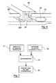
- the invention therefore relates to a roof module, one embodiment of which is illustrated in figure 1 .
- This roof module 10 is intended to be secured to the structure of a vehicle.
- It comprises a roof panel 11, for example metal or plastic. Struts 14 and 15 can be mounted on this panel. An opening 12 has been formed in this panel 11, in order to receive a glazed surface 13.
- this glazed surface has a general U shape, which has areas with weak radii. This is particularly the case inside the U, where the radius r can be less than 5 cm. In this area, a conventional joint often tends to yawn.
- the panes are advantageously tempered glass, for example with a thickness of between 3 and 5 mm.
- the rectangular glazed elements 24, 25, 28 or 29 may be fixed or movable.
- One of the advantages of the invention is that it makes it easy to replace a fixed element with a movable element, and vice versa, without modifying the roof panel.
- worn joints are used, as illustrated on the Figures 3 and 4 .
- the seal 31 has a substantially planar surface 311, and two securing branches 312 and 313 whose bases are parallel and perpendicular to the finishing surface 311. These branches have curved ends 3121, 3131 ' extending in substantially opposite directions.
- the roof panel 11 has a main recess 111 provided to receive the edge of a glazed element and the corresponding glue joint.
- This recess 111 extends substantially parallel to the main surface of the panel at a distance such that the glazed element is in the same plane, when the assembly is completed.
- Another intermediate recess 112 is provided, a few tenths of a millimeter, at the edge of the main surface of the panel. It allows to receive an end 3111 of the finishing surface 311, so that it is in alignment with the roof panel, to obtain a flush appearance.
- the roof panel further comprises, on the main recess 111, a rib 113, provided to cooperate with the securing branches of the seal, and defining a housing for the branch 312, in cooperation with the connecting edge 114.
- the assembly is then as follows: the glazed element 32 is bonded to the recess 111, with the aid of an adhesive joint 33, a few millimeters away from the edge of the glazed element, so as to then allow the placing the peripheral seal 31.
- This seal is then brought back after securing the glazed element on the roof panel. It is a sheathed seal, which is inserted by force, so that the two securing branches 312 and 313 overlap the rib.
- the branch 312 then straddles the periphery of the glazed element, using on the one hand the end 3112 of the flat part, and on the other hand the curved edge 3121. This gives a good seal.
- the thickness of the end 3112 is gradually reduced so that the assembly has a substantially flush appearance.
- the other securing branch 313 is immobilized in the housing defined by the rib and the connecting edge.
- the curved end 3131 forcing against the connecting edge 114, to ensure a locking of the assembly. If necessary, an undercut can be provided for a better connection, if necessary.
- the peripheral seal is provided adapted to a connection between two glazed elements 41 and 42. These elements have, once again, been previously glued on the roof panel using glue joints 43, 44. As before, these glue joints are slightly offset from the edge of the glazed elements, to then allow the establishment of the seal 45, which straddles a rib 46.
- the seal 45 is similar to that presented in figure 3 , except that it is symmetrical, since it acts on each side on a glazed element 41, 42. It therefore differs essentially from the seal already described by its finishing surface 451, which can be flat or on the contrary have two ends gradually decreasing, as the end 3112 in figure 3 .
- all the joints are in the form of a single molded element, also called spider.
- an advantage of the invention is that it allows, easily, to replace fixed glazed elements with movable glass elements, for example by sliding.
- the figure 5 presents the case of a movable glazed element 51, replacing the fixed glazed element 32 of the figure 3 .
- the peripheral seal has been slightly modified compared to the figure 3 . It always has securing branches 312, 313, which overlap the rib 113, and a finishing portion bearing on the intermediate recess 112.
- the peripheral seal 63 overlaps the rib 64.
- the movable member 65 bears on the curved end 631 of the seal.
- the figure 7 summarizes the method of manufacturing a roof module according to the invention, in the form of a simplified flowchart.
- the main components of the module namely the roof panel 71 and the glazed element (s) 72, are obtained or manufactured.
- the glazed elements fixed to the roof panel are then secured (73). These are secured by gluing, using a bonding joint positioned a few millimeters from the edge of the glazed element, so as to leave sufficient space for the peripheral seal.
- peripheral seal (74).
- the installation is guided by the ribs provided for this purpose on the roof panel.
- the peripheral seal is in the form of a set allowing an implementation of all the edges of each of the fixed glazed panels.
- the approach is similar when one or more glazed elements are mobile.
- the movable glass elements are secured to the roof panel using known means to ensure and control their mobility in a conventional manner, for example by sliding and / or tilting.
- the glue joints are replaced by a seal, for example tubular.
- the glue joints between two glazed elements are designed so that the movable element comes to bear against it.
Landscapes
- Engineering & Computer Science (AREA)
- Mechanical Engineering (AREA)
- Body Structure For Vehicles (AREA)
- Automobile Manufacture Line, Endless Track Vehicle, Trailer (AREA)
Claims (10)
- Dachmodul für ein Kraftfahrzeug, das mindestens ein verglastes Element (13, 32) aufweist, welches eine in einem Dachpaneel (11) angebrachte Öffnung (12) verschließt, wobei dieses Dachpaneel so auf dem besagten Fahrzeug anzubringen ist, dass es mindestens einen Teil des Fahrzeugdachs bildet,
dadurch gekennzeichnet, dass mindestens eines der besagten verglasten Elemente mit dem Dachpaneel mit Hilfe eines Kleberstrangs (33) verbunden ist, das dem Rand des besagten verglasten Elementes (13, 32) in einer Entfernung von 2 bis 20 mm des Randes des verglasten Elementes folgt, und
dass es eine umlaufende Dichtung (31) aufweist, die nach Verklebung zwischen dem besagten Rand des verglasten Elementes (13, 32) und dem entsprechenden Rand des besagten Dachpaneels (11) montiert wird, wobei die besagte Dichtung (31) eine in etwa ebene Abschlussfläche (311) und zwei Verbindungszweige (312, 313) aufweist, von denen:- ein erster Zweig (312) derart gestaltet ist, dass dessen Ende in Richtung des besagten Kleberstrangs (33) verläuft und sich auf das besagte verglaste Element (13, 32) abstützt;- ein zweiter Zweig (313) in einer dafür im besagten Dachpaneel vorgesehenen Blockiereinlassung eingelegt wird,wobei das besagte Dachpaneel (11) mindestens eine Führungs- und Halterippe (113) der besagten umlaufenden Dichtung (31) aufweist, die sich in etwa senkrecht zur Ebene des besagten Dachpaneels (11) erstreckt und mit dem zwischen den besagten Verbindungszweigen (312, 313) der umlaufenden Dichtung (31) begrenzten Raum zusammenwirkt. - Dachmodul für ein Kraftfahrzeug nach Anspruch 1, dadurch gekennzeichnet, dass die besagte Öffnung (12) im Allgemeinen U-förmig gestaltet ist, deren innerer und unterer Teil einen Radius von weniger als 5 cm bildet.
- Dachmodul nach einem der Ansprüche 1 und 2, dadurch gekennzeichnet, dass das besagte Dachpaneel (11) einen Rücksprung (111) in der Nähe des Randes der besagten Öffnung (12) aufweist, so dass die besagte Abschlussfläche (311) sich auf dem besagten Rücksprung (111) abstützt und in etwa in der Verlängerung des sichtbaren Teils des besagten Dachpaneels (11) liegt.
- Dachmodul nach einem der Ansprüche 1 bis 3, dadurch gekennzeichnet, dass es mindestens zwei verglaste Elemente (13, 32) aufweist.
- Dachmodul nach Anspruch 4, dadurch gekennzeichnet, dass mindestens eines der besagten verglasten Elemente zwischen einer geschlossenen und mindestens einer offenen Position beweglich ist bzw. sind.
- Dachmodul nach Anspruch 5, dadurch gekennzeichnet, dass für mindestens einen Rand des besagten beweglichen verglasten Elementes (51), der besagte Kleberstrang (33) durch eine mit dem besagten Dachpaneel verbundene rohrförmige Dichtung ersetzt wird.
- Dachmodul nach einem der Ansprüche 5 und 6, dadurch gekennzeichnet, dass für mindestens einen Rand des besagten beweglichen verglasten Elementes (51), der besagte Kleberstrang (33) weggelassen wird, wobei das besagte bewegliche verglaste Element in der geschlossenen Position die besagte umlaufende Dichtung (31) berührt.
- Dachmodul nach einem der Ansprüche 1 bis 7, dadurch gekennzeichnet, dass die besagte umlaufende Dichtung (31) eine einzige geformte Einheit bildet.
- Kraftfahrzeug, dadurch gekennzeichnet, dass es ein Dachmodul aufweist, das mindestens ein verglastes Element (13, 32) aufweist, welches eine in einem Dachpaneel (11) angebrachte Öffnung (12) verschließt, wobei dieses Dachpaneel so auf dem Fahrzeug anzubringen ist, dass es mindestens einen Teil des Fahrzeugdachs bildet,
dadurch gekennzeichnet, dass mindestens eines der besagten verglasten Elemente (13, 32) mit dem Dachpaneel (11) mit Hilfe eines Kleberstrangs (33) verbunden ist, welcher dem Rand des besagten verglasten Elementes (13, 32) in einer Entfernung von 2 bis 20 mm des besagten Randes des verglasten Elementes (13, 32) folgt, und
dass es eine umlaufende Dichtung (31) aufweist, die nach Verklebung zwischen dem besagten Rand des verglasten Elementes (13, 32) und dem entsprechenden Rand des besagten Dachpaneels (11) montiert wird, wobei die besagte Dichtung (31) eine in etwa ebene Abschlussfläche (311) und zwei Verbindungszweige (312, 313) aufweist, von denen:- ein erster Zweig derart gestaltet ist, dass dessen Ende in Richtung des besagten Kleberstrangs (33) verläuft und sich auf das besagte verglaste Element (13, 32) abstützt;- ein zweiter Zweig in einer dafür im besagten Dachpaneel vorgesehenen Blockiereinlassung eingelegt wird,wobei das besagte Dachpaneel (11) mindestens eine Führungs- und Halterippe (113) der besagten umlaufenden Dichtung (31) aufweist, die sich in etwa senkrecht zur Ebene des besagten Dachpaneels (11) erstreckt und mit dem zwischen den besagten Verbindungszweigen (312, 313) der umlaufenden Dichtung (31) begrenzten Raum zusammenwirkt. - Herstellungsverfahren eines Dachmoduls für Kraftfahrzeuge nach einem der Ansprüche 1 bis 8, das mindestens ein verglastes Element (13, 32) aufweist, welches eine in einem Dachpaneel (11) angebrachte Öffnung (12) verschließt, wobei dieses Dachpaneel so auf dem besagten Fahrzeug anzubringen ist, dass es mindestens einen Teil des Fahrzeugdachs bildet,
dadurch gekennzeichnet, dass es die folgenden Schritte umfasst:- Erhalten des besagten Dachpaneels und des verglasten Elementes bzw. der besagten verglasten Elemente;- Verbinden von mindestens einem der besagten verglasten Elemente mit dem besagten Dachpaneel mit Hilfe eines Kleberstrangs (33), der dem Rand des besagten verglasten Elementes in einer Entfernung von 2 bis 20 mm des besagten Randes des verglasten Elementes folgt;- Anbringen einer umlaufenden Dichtung (31) nach dem Verkleben zwischen dem besagten Rand des verglasten Elementes und dem entsprechenden Rand des besagten Dachpaneels, wobei die besagte Dichtung eine in etwa ebene Abschlussfläche und zwei Verbindungszweige aufweist, von denen- ein erster Zweig (312) derart gestaltet ist, dass dessen Ende in Richtung des besagten Kleberstrangs (33) verläuft und sich auf das besagte verglaste Element (13, 32) abstützt;- ein zweiter Zweig (313) in einer dafür im besagten Dachpaneel vorgesehenen Blockiereinlassung eingelegt wird,- wobei die umlaufende Dichtung so angebracht wird, dass eine auf dem besagten Dachpaneel vorgesehene Führungs- und Halterippe (113) der besagten umlaufenden Dichtung (31), die sich in etwa senkrecht zur Ebene des besagten Dachpaneels erstreckt, mit dem zwischen den besagten Verbindungszweigen der umlaufenden Dichtung begrenzten Raum zusammenwirkt.
Applications Claiming Priority (1)
| Application Number | Priority Date | Filing Date | Title |
|---|---|---|---|
| FR0500912A FR2881392B1 (fr) | 2005-01-28 | 2005-01-28 | Module de toit a element vitre pour vehicule automobile, vehicule automobile et procede de fabrication correspondants |
Publications (2)
| Publication Number | Publication Date |
|---|---|
| EP1685998A1 EP1685998A1 (de) | 2006-08-02 |
| EP1685998B1 true EP1685998B1 (de) | 2010-03-10 |
Family
ID=34955457
Family Applications (1)
| Application Number | Title | Priority Date | Filing Date |
|---|---|---|---|
| EP05112674A Expired - Fee Related EP1685998B1 (de) | 2005-01-28 | 2005-12-21 | Dachmodul mit einem Fensterelement für ein Kraftfahrzeug, korrespondierendes Kraftfahrzeug und Verfahren zur Herstellung |
Country Status (3)
| Country | Link |
|---|---|
| EP (1) | EP1685998B1 (de) |
| DE (1) | DE602005019847D1 (de) |
| FR (1) | FR2881392B1 (de) |
Family Cites Families (7)
| Publication number | Priority date | Publication date | Assignee | Title |
|---|---|---|---|---|
| GB702743A (en) * | 1950-09-15 | 1954-01-20 | Thomas John Robert Bright | Improvements in draught excluding strips, beadings, mouldings and the like |
| DE2634717C2 (de) * | 1976-08-02 | 1978-09-21 | Karl Kaessbohrer, Fahrzeugwerke Gmbh, 7900 Ulm | Halterung für Windschutzfenster in Kraftfahrzeugen |
| GB2037354A (en) * | 1978-10-26 | 1980-07-09 | United Carr Ltd | Windscreen Moulding Clip |
| DE2855526A1 (de) * | 1978-12-22 | 1980-07-10 | Porsche Ag | Halterung der scheiben von kraftfahrzeugen |
| FR2581606B1 (fr) * | 1985-05-07 | 1991-01-11 | Renault Vehicules Ind | Profil de protection de jonction collee de vitre sur une paroi de vehicule |
| DE19648330B4 (de) * | 1996-11-22 | 2006-05-11 | Adam Opel Ag | Kraftfahrzeugkarosserie |
| DE10254573B4 (de) * | 2001-11-28 | 2007-08-16 | Daimlerchrysler Ag | Abstandsgenauer Zusammenbau eines Dachmoduls mit einer Fahrzeugkarosserie |
-
2005
- 2005-01-28 FR FR0500912A patent/FR2881392B1/fr not_active Expired - Fee Related
- 2005-12-21 DE DE602005019847T patent/DE602005019847D1/de not_active Expired - Lifetime
- 2005-12-21 EP EP05112674A patent/EP1685998B1/de not_active Expired - Fee Related
Also Published As
| Publication number | Publication date |
|---|---|
| FR2881392A1 (fr) | 2006-08-04 |
| DE602005019847D1 (de) | 2010-04-22 |
| FR2881392B1 (fr) | 2007-03-30 |
| EP1685998A1 (de) | 2006-08-02 |
Similar Documents
| Publication | Publication Date | Title |
|---|---|---|
| EP2512850B1 (de) | Heckklappe eines kraftfahrzeuges | |
| CA2983670A1 (fr) | Vitrage de vehicule comprenant une platine pour la fixation de plusieurs accessoires, platine et procede de fixation | |
| FR2957047A1 (fr) | Structure de carrosserie brute d'un vehicule automobile leger avec module de bequet arriere | |
| EP3647093A1 (de) | Verglaste vorrichtung eines fahrzeugs mit demontierbarem gleitschuh, entsprechende tür, entsprechendes fahrzeug und montageverfahren | |
| WO2008029045A2 (fr) | Agrafe pour fixation de bandeau de portiere de vehicule automobile | |
| FR3070631A1 (fr) | Insert pour une coulisse de vitrage de vehicule | |
| EP2121362A2 (de) | Verfahren zur anordnung einer glasur auf ihrem halter durch verkleben, sowie mittel zur durchführung des verfahrens | |
| EP1975359A1 (de) | Vorrichtung zur Vormontage einer Befestigungsschraube für das Fenster eines Fensterhebers eines Fahrzeugs | |
| EP1685998B1 (de) | Dachmodul mit einem Fensterelement für ein Kraftfahrzeug, korrespondierendes Kraftfahrzeug und Verfahren zur Herstellung | |
| EP3495183A1 (de) | Fahrzeug-öffnungselement, das ein vorspringendes einsatzelement umfasst | |
| EP1827881B1 (de) | Panoramawindschutzschreibe für ein kraftfahrzeug | |
| FR2952995A1 (fr) | Ensemble formant cale | |
| EP4126528B1 (de) | Verbundverglasung für ein kraftfahrzeug, insbesondere seitenverglasung | |
| FR2851204A1 (fr) | Patte de fixation d'un leve-vitre, leve-vitre et carrosserie de vehicule | |
| EP4220008B1 (de) | Kraftfahrzeugpaneel mit integriertem leuchtelement | |
| FR2886614A1 (fr) | Joint peripherique d'un vitrage d'optique d'un vehicule automobile | |
| EP1767438A1 (de) | A-Säule für eine Kraftfahrzeugkarosserie | |
| FR3097489A1 (fr) | Habillage intérieur d’ouvrant de véhicule supportant une caméra. | |
| FR2957556A1 (fr) | Fenestron multifonctionnel et vehicule equipe dudit fenestron. | |
| FR3070942A1 (fr) | Ouvrant arriere de vehicule automobile comprenant un module amovible | |
| EP1477355B1 (de) | Autotür mit Schutztsmitteln des oberen Bereichs einer flachmontierten Scheibe, Erweiterung des Schutzes und Fahrzeug hierzu. | |
| EP0716953B1 (de) | Befestigung einer Scheinwerfereinheit für Kraftfahrzeuge | |
| EP1610005B1 (de) | Klammer für die Befestigung einer Schraube an Teile eines Automobils | |
| EP1741586B1 (de) | Abschlussvorrichtung für eine Fahrzeugöffnung mit innerer Dichtung, Herstellungsverfahren und entsprechendes Fahrzeug | |
| FR2581938A3 (fr) | Porte de vehicule amelioree pouvant etre pre-assemblee. |
Legal Events
| Date | Code | Title | Description |
|---|---|---|---|
| PUAI | Public reference made under article 153(3) epc to a published international application that has entered the european phase |
Free format text: ORIGINAL CODE: 0009012 |
|
| AK | Designated contracting states |
Kind code of ref document: A1 Designated state(s): AT BE BG CH CY CZ DE DK EE ES FI FR GB GR HU IE IS IT LI LT LU LV MC NL PL PT RO SE SI SK TR |
|
| AX | Request for extension of the european patent |
Extension state: AL BA HR MK YU |
|
| 17P | Request for examination filed |
Effective date: 20060907 |
|
| AKX | Designation fees paid |
Designated state(s): DE FR |
|
| 17Q | First examination report despatched |
Effective date: 20090119 |
|
| GRAP | Despatch of communication of intention to grant a patent |
Free format text: ORIGINAL CODE: EPIDOSNIGR1 |
|
| GRAS | Grant fee paid |
Free format text: ORIGINAL CODE: EPIDOSNIGR3 |
|
| GRAA | (expected) grant |
Free format text: ORIGINAL CODE: 0009210 |
|
| AK | Designated contracting states |
Kind code of ref document: B1 Designated state(s): DE FR |
|
| REF | Corresponds to: |
Ref document number: 602005019847 Country of ref document: DE Date of ref document: 20100422 Kind code of ref document: P |
|
| RAP2 | Party data changed (patent owner data changed or rights of a patent transferred) |
Owner name: ADVANCED COMFORT SYSTEMS FRANCE SAS - ACS FRANCE |
|
| PLBE | No opposition filed within time limit |
Free format text: ORIGINAL CODE: 0009261 |
|
| STAA | Information on the status of an ep patent application or granted ep patent |
Free format text: STATUS: NO OPPOSITION FILED WITHIN TIME LIMIT |
|
| 26N | No opposition filed |
Effective date: 20101213 |
|
| PGFP | Annual fee paid to national office [announced via postgrant information from national office to epo] |
Ref country code: FR Payment date: 20120111 Year of fee payment: 7 |
|
| PGFP | Annual fee paid to national office [announced via postgrant information from national office to epo] |
Ref country code: DE Payment date: 20120102 Year of fee payment: 7 |
|
| REG | Reference to a national code |
Ref country code: FR Ref legal event code: ST Effective date: 20130830 |
|
| REG | Reference to a national code |
Ref country code: DE Ref legal event code: R119 Ref document number: 602005019847 Country of ref document: DE Effective date: 20130702 |
|
| PG25 | Lapsed in a contracting state [announced via postgrant information from national office to epo] |
Ref country code: DE Free format text: LAPSE BECAUSE OF NON-PAYMENT OF DUE FEES Effective date: 20130702 |
|
| PG25 | Lapsed in a contracting state [announced via postgrant information from national office to epo] |
Ref country code: FR Free format text: LAPSE BECAUSE OF NON-PAYMENT OF DUE FEES Effective date: 20130102 |