EP1685995B1 - Führungseinrichtung und Schiebedachkonstruktion mit einer solchen Vorrichtung - Google Patents
Führungseinrichtung und Schiebedachkonstruktion mit einer solchen Vorrichtung Download PDFInfo
- Publication number
- EP1685995B1 EP1685995B1 EP05100607A EP05100607A EP1685995B1 EP 1685995 B1 EP1685995 B1 EP 1685995B1 EP 05100607 A EP05100607 A EP 05100607A EP 05100607 A EP05100607 A EP 05100607A EP 1685995 B1 EP1685995 B1 EP 1685995B1
- Authority
- EP
- European Patent Office
- Prior art keywords
- slide shoe
- guide channel
- additional
- guiding assembly
- guide
- Prior art date
- Legal status (The legal status is an assumption and is not a legal conclusion. Google has not performed a legal analysis and makes no representation as to the accuracy of the status listed.)
- Active
Links
- 238000010276 construction Methods 0.000 title claims description 9
- 230000000712 assembly Effects 0.000 claims description 3
- 238000000429 assembly Methods 0.000 claims description 3
- 230000000694 effects Effects 0.000 description 7
- 230000002411 adverse Effects 0.000 description 1
Images

Classifications
-
- B—PERFORMING OPERATIONS; TRANSPORTING
- B60—VEHICLES IN GENERAL
- B60J—WINDOWS, WINDSCREENS, NON-FIXED ROOFS, DOORS, OR SIMILAR DEVICES FOR VEHICLES; REMOVABLE EXTERNAL PROTECTIVE COVERINGS SPECIALLY ADAPTED FOR VEHICLES
- B60J7/00—Non-fixed roofs; Roofs with movable panels, e.g. rotary sunroofs
- B60J7/02—Non-fixed roofs; Roofs with movable panels, e.g. rotary sunroofs of sliding type, e.g. comprising guide shoes
Definitions
- the invention relates to a guiding assembly according to the preamble of the main claim.
- a guiding assembly can be found in an open roof construction for a vehicle, in which a closure means for opening and closing a roof opening is provided with slide shoes positioned in guide channels connected to a stationary roof part of the vehicle: US-A1-2002/0089217 (closest prior art) shows such a guiding assembly with two guide shoes spaced longitudinally from each other.
- Document DE-C-4107129 already shows a state of the art slide shoe for application in such a guiding assembly.
- slide shoes should be positioned in the guide channel in such a manner that a certain amount of friction is generated between said slide shoe and cooperating guide channel.
- such a slide shoe often comprises an internal spring member which should have a certain extent for ensuring a proper operation. This is the reason, why such a slide shoe has an oblong shape.
- the guide channel comprises at least one curved section in which it diverges from its otherwise longitudinal direction.
- a curved section is needed to provide the closure means with a desired trajectory of movement.
- guide channel comprising at least one curved section and a slide shoe having an oblong shape leads, however, to a disadvantage.
- a slide shoe basically comprises two long sides and two short sides (although generally being rounded). Positioned in a straight part of the guide channel said long sides will engage the opposite guide surfaces of the guide channel. The distance between the guide surfaces of the guide channel in such a straight section thereof basically will correspond with the distance between the opposed long sides of the slide shoe.
- a guiding assembly of the type referred to above is provided, which is characterised as set forth in the main claim.
- the additional slide shoe has smaller dimensions than the primary slide shoe and, consequently, the additional guide channel is smaller in cross-section. Because, in this embodiment, the additional slide shoe has smaller dimensions than the primary slide shoe, the above explained negative effects will present itself in a far lesser extent with such an additional slide shoe then in relation to the primary slide shoe.
- One shape of the additional slide shoe which proves to be very effective in eliminating the adverse effects referred to above, is a shape, in which the additional slide shoe has a substantially oblong cross-section with two opposite semi-circular ends.
- the curved section of the guide channel is positioned at one end of the guide channel.
- the guide channel comprises more than one curved section.
- the invention relates also to an open roof construction for a vehicle, comprising a roof opening defined in a stationary roof part of the vehicle and a movable closure means for opening and closing said roof opening, wherein said closure means comprises slide shoes and said stationary roof part comprises guide channels, said slide shoes and guide channels defining guiding assemblies in accordance with the present invention.
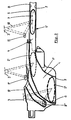
- FIG. 1 shows a vehicle having a stationary roof part 1 in which an open roof construction is provided.
- Said open roof construction basically comprises a roof opening 2 defined in the stationary roof part 1 and a movable closure means 3 for opening and closing said roof opening.
- the operation of the movable closure means 3 may be manually or motor-driven, as is known per se.
- guiding assemblies For defining the trajectory of the movable closure means 3 during its movement between a position for opening the roof opening 2 and a position for closing the roof opening, and vice versa, guiding assemblies are provided comprising guide channels 4 (indicated by broken lines) for cooperation with slide shoes 5 attached to longitudinal sides 6 of the closure means 3.
- such guide channels 4 often comprise at least one curved section which is meant for providing the closure means 3 with a relative vertical movement with respect to the stationary roof part 1, in addition to its relative horizontal movement for opening and closing the roof opening 2.
- a curved section of the guide channel 4 will connect to a basically straight section of the guide channel 4.
- figure 2 in which, on a larger scale and schematically, part of a guide channel 4 is illustrated.
- the right part of figure shows a straight section 4' of a guide channel 4. It comprises two opposite guide surfaces 7 and 8 which cooperate with a slide shoe 5 positioned in the guide channel.
- the slide shoe has an oblong shape and is provided internally with spring means 9 (only indicated schematically) for maintaining the engagement between the slide shoe 5 and the guide surfaces 7 and 8 of the guide channel 4.
- guide channel 4 also could comprise additional guide surfaces, e.g. in parallel to the plane of the drawing.
- a support means 10 (again only indicated purely schematically) defines a connection between the slide shoe 5 and the closure means 3.
- Said support means 10 further is connected to an additional slide shoe 11 which, as can be seen clearly in figure 2 , has smaller dimensions then the primary slide shoe 5.
- the additional slide shoe 11 always maintains a stationary relative position with respect to the primary slide shoe 5.
- a curved section 4" of the guide channel 4 is represented.
- the slide shoe 5 enters this curved section 4" of the guide channel, it will assume positions such as 5' and 5" indicated in dotted lines.
- position 5' the slide shoe has just started entering the curved section 4" of the guide channel and in its position 5" the slide shoe has reached an end position in the curved section 4" of the guide channel.
- the slide shoe now engages the opposite guide surfaces 7 and 8 of the guide channel 4 with its left and right ends (rather than with its upper and lower sides as is the case in the straight section 4' of the guide channel) the internal spring means 9 have expanded the slide shoe towards its non-loaded shape.
- the additional slide shoe 11 has a substantially oblong cross-section with two semi-circular ends. It, however, is conceivable too that it has a different shape, such as for example circular.
Claims (5)
- Führungsanordnung, aufweisend einen Führungskanal (4) mit zwei gegenüberliegenden Führungsflächen (7, 8) und einen Gleitschuh (5), der in dem Führungskanal positioniert ist und mit den beiden Führungsflächen zusammenwirkt, wobei der Führungskanal wenigstens einen gekrümmten Abschnitt (4") aufweist, und wobei der Gleitschuh eine längliche Form hat, wobei die Führungsanordnung wenigstens in der Nähe ihres gekrümmten Abschnitts (4") einen zusätzlichen Führungskanal (12) zum Zusammenwirken mit einem zusätzlichen Gleitschuh (11) aufweist, der mit dem primären Gleitschuh (5) verbunden ist, dadurch gekennzeichnet, dass die Position des zusätzlichen Gleitschuhes (11) relativ zu dem Gleitschuh (5) derart ist, dass, wenn der Gleitschuh (5) in, dem gekrümmten Abschnitt (4") des Führungskanals (4) positioniert ist, der zusätzliche Gleitschuh (11) in dem zusätzlichen Führungskanal (12) und in der Nähe des Gleitschuhes (5) positioniert ist.
- Führungsanordnung nach Anspruch 1, wobei der zusätzliche Gleitschuh (11) kleinere Abmessungen als der primäre Gleitschuh (5) hat, und folglich der zusätzliche Führungskanal (12) im Querschnitt kleiner ist.
- Führungsanordnung nach Anspruch 2, wobei der zusätzliche Gleitschuh (11) einen im Wesentlichen länglichen Querschnitt mit zwei entgegengesetzten halbkreisförmigen Enden hat.
- Führungsanordnung nach einem der vorhergehenden Ansprüche, wobei der gekrümmte Abschnitt (4") des Führungskanals (4) an dem einen Ende des Führungskanals positioniert ist.
- Öffnungsfähige Dachkonstruktion für ein Fahrzeug, aufweisend eine Dachöffnung (2), die in einem ortsfesten Dachteil (1) des Fahrzeuges definiert ist, und ein bewegbares Schließmittel (3) zum Öffnen und Schließen der Dachöffnung, wobei das Schließmittel Gleitschuhe (5) aufweist und das ortsfeste Dachteil Führungskanäle (4) aufweist, wobei die Gleitschuhe und die Führungskanäle Führungsanordnungen nach einem der vorhergehenden Ansprüche definieren.
Priority Applications (4)
| Application Number | Priority Date | Filing Date | Title |
|---|---|---|---|
| DE602005011397T DE602005011397D1 (de) | 2005-01-31 | 2005-01-31 | Führungseinrichtung und Schiebedachkonstruktion mit einer solchen Vorrichtung |
| EP05100607A EP1685995B1 (de) | 2005-01-31 | 2005-01-31 | Führungseinrichtung und Schiebedachkonstruktion mit einer solchen Vorrichtung |
| JP2005355315A JP4855058B2 (ja) | 2005-01-31 | 2005-12-08 | 案内アセンブリおよびそれを備えた開放式屋根構造体 |
| US11/341,811 US7267398B2 (en) | 2005-01-31 | 2006-01-27 | Guiding assembly and open roof construction provided therewith |
Applications Claiming Priority (1)
| Application Number | Priority Date | Filing Date | Title |
|---|---|---|---|
| EP05100607A EP1685995B1 (de) | 2005-01-31 | 2005-01-31 | Führungseinrichtung und Schiebedachkonstruktion mit einer solchen Vorrichtung |
Publications (2)
| Publication Number | Publication Date |
|---|---|
| EP1685995A1 EP1685995A1 (de) | 2006-08-02 |
| EP1685995B1 true EP1685995B1 (de) | 2008-12-03 |
Family
ID=34938600
Family Applications (1)
| Application Number | Title | Priority Date | Filing Date |
|---|---|---|---|
| EP05100607A Active EP1685995B1 (de) | 2005-01-31 | 2005-01-31 | Führungseinrichtung und Schiebedachkonstruktion mit einer solchen Vorrichtung |
Country Status (4)
| Country | Link |
|---|---|
| US (1) | US7267398B2 (de) |
| EP (1) | EP1685995B1 (de) |
| JP (1) | JP4855058B2 (de) |
| DE (1) | DE602005011397D1 (de) |
Families Citing this family (5)
| Publication number | Priority date | Publication date | Assignee | Title |
|---|---|---|---|---|
| DE202005007475U1 (de) * | 2005-05-11 | 2005-07-14 | Arvinmeritor Gmbh | Führungsschiene für ein Kfz-Schiebedachsystem |
| EP2711219B1 (de) * | 2012-09-25 | 2015-07-22 | Inalfa Roof Systems Group B.V. | Antriebsmechanismus und damit ausgestattete offene Dachkonstruktion |
| DE102015201587A1 (de) * | 2015-01-29 | 2016-08-04 | Bos Gmbh & Co. Kg | Antriebssystem für einen beweglichen Dachteil eines Dachmoduls eines Kraftfahrzeugs |
| US10532639B1 (en) * | 2018-09-06 | 2020-01-14 | AISIN Technical Center of America, Inc. | Holding assembly for a sunroof rail system |
| US10618387B2 (en) * | 2018-09-06 | 2020-04-14 | AISIN Technical Center of America, Inc. | Sunroof rail guide assembly |
Family Cites Families (6)
| Publication number | Priority date | Publication date | Assignee | Title |
|---|---|---|---|---|
| US2869923A (en) * | 1955-07-29 | 1959-01-20 | Mulichak Steven | Retractable hard top convertible |
| DE4107129C1 (en) | 1991-03-06 | 1992-06-04 | Webasto Ag Fahrzeugtechnik, 8035 Stockdorf, De | Guide arrangement for adjustable parts of vehicle roof - has lengthwise groove(s) for sliding jaw coated with solid lubricant |
| US6474725B2 (en) * | 2000-07-26 | 2002-11-05 | Meritor Light Vehicle Technology, Llc | Reinforced cargo doors |
| DE10055790B4 (de) * | 2000-11-10 | 2005-03-17 | Webasto Ag | Öffnungsfähiges Fahrzeugdach |
| FR2818931B1 (fr) * | 2001-01-04 | 2003-03-07 | France Design | Toit escamotable pour vehicule a elements coulissants |
| US6419314B1 (en) | 2001-01-05 | 2002-07-16 | Johnson Controls Technology Company | Vehicle accessory with sliding cover |
-
2005
- 2005-01-31 DE DE602005011397T patent/DE602005011397D1/de active Active
- 2005-01-31 EP EP05100607A patent/EP1685995B1/de active Active
- 2005-12-08 JP JP2005355315A patent/JP4855058B2/ja not_active Expired - Fee Related
-
2006
- 2006-01-27 US US11/341,811 patent/US7267398B2/en active Active
Also Published As
| Publication number | Publication date |
|---|---|
| JP4855058B2 (ja) | 2012-01-18 |
| US7267398B2 (en) | 2007-09-11 |
| DE602005011397D1 (de) | 2009-01-15 |
| EP1685995A1 (de) | 2006-08-02 |
| JP2006206033A (ja) | 2006-08-10 |
| US20060170254A1 (en) | 2006-08-03 |
Similar Documents
| Publication | Publication Date | Title |
|---|---|---|
| EP1685995B1 (de) | Führungseinrichtung und Schiebedachkonstruktion mit einer solchen Vorrichtung | |
| EP2017108B1 (de) | Offene Dachkonstruktion für ein Fahrzeug | |
| US8459730B2 (en) | Roof apparatus | |
| EP1777117B1 (de) | Installationsvorrichtung | |
| US9822571B2 (en) | Window clamp and assembly for window regulator | |
| US20080244981A1 (en) | Window clamp assembly for window regulator | |
| EP2048012A1 (de) | Offene Dachkonstruktion | |
| EP2450212A2 (de) | Dachvorrichtung für ein Fahrzeug | |
| EP1424234B1 (de) | Konstruktion eines öffnungsfähigen Fahrzeugdaches | |
| JPH07217604A (ja) | リザーブタンクの取付構造 | |
| US20160185196A1 (en) | Vehicle sunroof device | |
| CN109895609A (zh) | 用于车辆的敞开车顶构造和包括敞开车顶构造的车辆 | |
| US6902245B1 (en) | Drawer slide | |
| EP2711218A1 (de) | Antriebsmechanismus und damit ausgestattete offene Dachkonstruktion | |
| CN109070708B (zh) | 用于车顶的组件 | |
| EP2711219B1 (de) | Antriebsmechanismus und damit ausgestattete offene Dachkonstruktion | |
| US6802560B2 (en) | Sunroof apparatus for vehicle | |
| US7484433B2 (en) | Shift lever apparatus | |
| US20130020838A1 (en) | Roof apparatus for vehicle | |
| US4888916A (en) | Drive arrangement for a window lifting mechanism | |
| US10479174B2 (en) | Opening and closing mechanism and sunroof device having the same | |
| CN111315251B (zh) | 拉链用拉头 | |
| EP1717080A1 (de) | Führungsvorrichtung | |
| US20050001447A1 (en) | Actuating device for open/close member of vehicle | |
| US4659107A (en) | Automatic seat belt system |
Legal Events
| Date | Code | Title | Description |
|---|---|---|---|
| PUAI | Public reference made under article 153(3) epc to a published international application that has entered the european phase |
Free format text: ORIGINAL CODE: 0009012 |
|
| AK | Designated contracting states |
Kind code of ref document: A1 Designated state(s): AT BE BG CH CY CZ DE DK EE ES FI FR GB GR HU IE IS IT LI LT LU MC NL PL PT RO SE SI SK TR |
|
| AX | Request for extension of the european patent |
Extension state: AL BA HR LV MK YU |
|
| 17P | Request for examination filed |
Effective date: 20061222 |
|
| AKX | Designation fees paid |
Designated state(s): DE FR GB |
|
| 17Q | First examination report despatched |
Effective date: 20071023 |
|
| GRAP | Despatch of communication of intention to grant a patent |
Free format text: ORIGINAL CODE: EPIDOSNIGR1 |
|
| GRAS | Grant fee paid |
Free format text: ORIGINAL CODE: EPIDOSNIGR3 |
|
| GRAA | (expected) grant |
Free format text: ORIGINAL CODE: 0009210 |
|
| AK | Designated contracting states |
Kind code of ref document: B1 Designated state(s): DE FR GB |
|
| REG | Reference to a national code |
Ref country code: GB Ref legal event code: FG4D |
|
| REF | Corresponds to: |
Ref document number: 602005011397 Country of ref document: DE Date of ref document: 20090115 Kind code of ref document: P |
|
| PLBE | No opposition filed within time limit |
Free format text: ORIGINAL CODE: 0009261 |
|
| STAA | Information on the status of an ep patent application or granted ep patent |
Free format text: STATUS: NO OPPOSITION FILED WITHIN TIME LIMIT |
|
| 26N | No opposition filed |
Effective date: 20090904 |
|
| GBPC | Gb: european patent ceased through non-payment of renewal fee |
Effective date: 20090303 |
|
| PG25 | Lapsed in a contracting state [announced via postgrant information from national office to epo] |
Ref country code: GB Free format text: LAPSE BECAUSE OF NON-PAYMENT OF DUE FEES Effective date: 20090303 |
|
| REG | Reference to a national code |
Ref country code: FR Ref legal event code: PLFP Year of fee payment: 12 |
|
| REG | Reference to a national code |
Ref country code: FR Ref legal event code: PLFP Year of fee payment: 13 |
|
| REG | Reference to a national code |
Ref country code: FR Ref legal event code: PLFP Year of fee payment: 14 |
|
| PGFP | Annual fee paid to national office [announced via postgrant information from national office to epo] |
Ref country code: FR Payment date: 20230125 Year of fee payment: 19 |
|
| PGFP | Annual fee paid to national office [announced via postgrant information from national office to epo] |
Ref country code: DE Payment date: 20240129 Year of fee payment: 20 |