EP1685907A1 - Method of removing unburned carbon from fly ash - Google Patents
Method of removing unburned carbon from fly ash Download PDFInfo
- Publication number
- EP1685907A1 EP1685907A1 EP04792117A EP04792117A EP1685907A1 EP 1685907 A1 EP1685907 A1 EP 1685907A1 EP 04792117 A EP04792117 A EP 04792117A EP 04792117 A EP04792117 A EP 04792117A EP 1685907 A1 EP1685907 A1 EP 1685907A1
- Authority
- EP
- European Patent Office
- Prior art keywords
- fly ash
- unburned carbon
- slurry
- collector
- flotation
- Prior art date
- Legal status (The legal status is an assumption and is not a legal conclusion. Google has not performed a legal analysis and makes no representation as to the accuracy of the status listed.)
- Granted
Links
Images
Classifications
-
- B—PERFORMING OPERATIONS; TRANSPORTING
- B03—SEPARATION OF SOLID MATERIALS USING LIQUIDS OR USING PNEUMATIC TABLES OR JIGS; MAGNETIC OR ELECTROSTATIC SEPARATION OF SOLID MATERIALS FROM SOLID MATERIALS OR FLUIDS; SEPARATION BY HIGH-VOLTAGE ELECTRIC FIELDS
- B03D—FLOTATION; DIFFERENTIAL SEDIMENTATION
- B03D1/00—Flotation
- B03D1/02—Froth-flotation processes
-
- B—PERFORMING OPERATIONS; TRANSPORTING
- B03—SEPARATION OF SOLID MATERIALS USING LIQUIDS OR USING PNEUMATIC TABLES OR JIGS; MAGNETIC OR ELECTROSTATIC SEPARATION OF SOLID MATERIALS FROM SOLID MATERIALS OR FLUIDS; SEPARATION BY HIGH-VOLTAGE ELECTRIC FIELDS
- B03D—FLOTATION; DIFFERENTIAL SEDIMENTATION
- B03D1/00—Flotation
- B03D1/08—Subsequent treatment of concentrated product
- B03D1/10—Removing adhering liquid from separated materials
-
- B—PERFORMING OPERATIONS; TRANSPORTING
- B03—SEPARATION OF SOLID MATERIALS USING LIQUIDS OR USING PNEUMATIC TABLES OR JIGS; MAGNETIC OR ELECTROSTATIC SEPARATION OF SOLID MATERIALS FROM SOLID MATERIALS OR FLUIDS; SEPARATION BY HIGH-VOLTAGE ELECTRIC FIELDS
- B03D—FLOTATION; DIFFERENTIAL SEDIMENTATION
- B03D1/00—Flotation
- B03D1/12—Agent recovery
-
- C—CHEMISTRY; METALLURGY
- C04—CEMENTS; CONCRETE; ARTIFICIAL STONE; CERAMICS; REFRACTORIES
- C04B—LIME, MAGNESIA; SLAG; CEMENTS; COMPOSITIONS THEREOF, e.g. MORTARS, CONCRETE OR LIKE BUILDING MATERIALS; ARTIFICIAL STONE; CERAMICS; REFRACTORIES; TREATMENT OF NATURAL STONE
- C04B18/00—Use of agglomerated or waste materials or refuse as fillers for mortars, concrete or artificial stone; Treatment of agglomerated or waste materials or refuse, specially adapted to enhance their filling properties in mortars, concrete or artificial stone
- C04B18/04—Waste materials; Refuse
- C04B18/06—Combustion residues, e.g. purification products of smoke, fumes or exhaust gases
- C04B18/08—Flue dust, i.e. fly ash
-
- Y—GENERAL TAGGING OF NEW TECHNOLOGICAL DEVELOPMENTS; GENERAL TAGGING OF CROSS-SECTIONAL TECHNOLOGIES SPANNING OVER SEVERAL SECTIONS OF THE IPC; TECHNICAL SUBJECTS COVERED BY FORMER USPC CROSS-REFERENCE ART COLLECTIONS [XRACs] AND DIGESTS
- Y02—TECHNOLOGIES OR APPLICATIONS FOR MITIGATION OR ADAPTATION AGAINST CLIMATE CHANGE
- Y02W—CLIMATE CHANGE MITIGATION TECHNOLOGIES RELATED TO WASTEWATER TREATMENT OR WASTE MANAGEMENT
- Y02W30/00—Technologies for solid waste management
- Y02W30/50—Reuse, recycling or recovery technologies
- Y02W30/91—Use of waste materials as fillers for mortars or concrete
Definitions
- the present invention relates to a method of removing unburned carbon from fly ash, and more particularly to a method of efficiently removing unburned carbon from the fly ash generated in coal firing power plants and so on and efficiently using the fly ash and the removed unburned carbon.
- Fly ash generated in coal firing power plants etc. is used for materials for cement and artificial lightweight aggregates, concrete admixture, etc.
- unburned carbon of fly ash will absorb AE water reducing agent etc., and will reduce the workability of the concrete.
- unburned carbon comes floating and there is harmful influence of a black part occurring in the connecting portion of the concrete.
- there was much unburned carbon of fly ash there was also a problem that the quality of an artificial lightweight aggregate deteriorated. Therefore, only fly ash with little unburned carbon was used for the materials of cement etc., the fly ash with high unburned carbon content could not be used effectively and was processed for reclamation as industrial waste.
- a technology for removing unburned carbon of coal ash is disclosed.
- this technology after powdery coal ash is agitated and mixed with nonaqueous solvent of a low specific gravity rather than water and water, the mixture is settled and is separated into water layer including coal ash and nonaqueous solvent including unburned carbon.
- the second patent document discloses a method of improving recovery rate and efficiently removing unburned carbon of coal ash by adding ionicity collector as a collector after adding acid to water slurry of coal ash in the process of coal ash processing with a hydrophobic process, in which collector is added to the water slurry of coal ash to make the unburned carbon hydrophobic, and flotation separation process, in which frother is added to the water slurry to generate air bubbles and the unburned carbon is adhered to the bubbles for flotation.
- the present invention has been made in consideration of the above problems, and the object thereof is to provide a method of efficiently removing unburned carbon from fly ash without special chemicals, and efficiently using fly ash and removed unburned carbon.
- the present invention is characterized in a method of removing unburned carbon from fly ash comprising the step of; adding water to fly ash to produce slurry; adding collector to the slurry; feeding the slurry and the collector to a submerged agitator having a rotation shaft penetrating a cylindrical main body in an axial direction thereof, plurality of chambers formed by dividing an inside of the main body in the axial direction thereof and an agitating vane fixed to the rotation shaft and rotating in each chamber, and adding shearing force to the slurry and collector; adding frother to the slurry and collector to which the sharing force is added; agitating the slurry and collector to generate air bubbles; and adhering unburned carbon of the fly ash to the air bubbles to rise the unburned carbon.
- each of the unburned carbon in slurry, true fly ash, and the collector can not only raise the distributed effect but transitionally generate activity energy (surface energy) on the surface of each distributed particle.
- unburned carbon can efficiently be removed from the original fly ash slurry.
- fly ash with 5.0% of unburned carbon can be reduced its unburned carbon content to only approximately 2%.
- by adding shearing force and performing surface modification unburned carbon of the fly ash can considerably reduced, and fly ash with approximately 0.5% of unburned carbon can be obtained.
- generally used collector such as kerosene can be used, and a small amount (about 15%) is sufficient for the collector to the quantity of unburned carbon. This makes it possible to reduce the amount of collector used, to allow little kerosene etc. to remain in the fly ash as a product and to make post-processing after the flotation process easy.
- agitation power In applying shearing force through the submerged agitator to the slurry and the collector, it is preferred to apply 0.7 kWh/m 3 or more and 10 kWh/m 3 or less of agitation power per amount of unit quantity of slurry. If the agitation power does not reach 0.7 kWh/m 3 , shearing force applied to the slurry and the collector is inadequate and unburned carbon cannot be removed efficiently, but the agitation power exceeds 10 kWh/m 3 , the energy consumed to the removal efficiency of unburned carbon becomes excessive and is not preferred.
- the fly ash concentration of the slurry is preferably adjusted to be 3 weight percent or more and 50 weight percent or less. If the fly ash concentration is lower than 3 weight percent, it is not preferable since the quantity of slurry increases too much to the fly ash, which should be processed. On the contrary, if the fly ash concentration exceeds 50 weight percent, it is not desirable since it may not form slurry.
- the amount of the collector added is 5 weight percent or more and 100 weight percent or less of the amount of unburned carbon.
- the amount of the collector added is less than 5 weight percent, the effect of adsorbing unburned carbon of fly ash falls and flotation separation performance cannot be raised, and when the amount of the collector added exceeds 100 weight percent of the amount of unburned carbon of fly ash, the effect as a collector may approach a limit, even if it makes the amount of addition increase, the cost of a collector only increases and it is not desirable.
- Water of the fly ash slurry after flotation separation is separated with a solid/liquid separator and can be reused to add to new fly ash slurry, and/or can be reused to erase bubbles when adhering unburned carbon to air bubbles, which lessens drainage out of the system as little as possible.
- the unburned carbon of the fly ash that was separated through flotation can be used as fuel.
- the utilization of the unburned carbon as fuel allows kerosene or the like used as a collector to efficiently be burned simultaneously.
- the unburned carbon of the fly ash which was separated through flotation, can be made into 1 weight percent or less, and it can be use as a mixing material for cement. This can suppress absorption of AE water reducing agent by unburned carbon etc. to the minimum and can prevent the fall of the workability of concrete. Moreover, it can also prevent floating up of the unburned carbon at the time of placing concrete, and a black part generated in the connecting portion of the concrete.
- the unburned carbon of the fly ash, which was separated through flotation, can be made into 1 weight percent or less, and it can be used as a material for lightweight aggregate. This makes it possible to produce precise lightweight artificial aggregate of high strength.
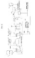
- Figure 1 shows an example of the system composition for enforcing a method of removing an unburned carbon from fly ash according to the present invention
- the system roughly comprises a slurry tank 2 for adding water to fly ash to generate slurry, a submerged agitator 4 which applies shearing force to the slurry and a collector after adding the collector to slurry to modify the surface of unburned carbon, a flotation machine 11 which separates the unburned carbon by adding a frother to the slurry, generating air bubbles, making the unburned carbon of fly ash adhere to these air bubbles, and making it rise, a solid/liquid separator 13 which carries out solid/liquid separation of the tailing from the flotation machine 11, a drier 14 for obtaining fly ash (product) which is made to dry the cake from solid/liquid separator 13, a filter press 18 for solid/liquid separating the froth from flotation machine 11 to obtain unburned carbon and so on.
- the slurry tank 2 is installed to produce slurry with adding water and fly ash, and is provided with an agitating vane to agitate the slurry therein.
- a fly ash tank 1 and water supply equipment are installed, and a pump 3 is arranged to send slurry to the submerged agitator 4 at the down stage of the slurry tank 2.
- the submerged agitator 4 is installed to add shearing force to the slurry and the collector and to modify the surface of the unburned carbon.
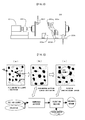
- a high-speed shearing mixer 20 shown in Fig. 2.
- the high-speed shearing mixer 20 is provided with a cylindrical main body 20a, plurality of partition walls 20c which divide main body 20a into plurality of chambers, and plurality of agitating vanes 20e radially fixed to a rotation shaft 20d, and the rotation shaft 20d and the agitating vanes 20e rotate through a motor 21 and a reduction gear 22.
- a kerosene tank 6, which stores kerosene as a collector, and a pump 5 for supplying the kerosene to the submerged agitator 4 are installed in the upper stage of the submerged agitator 4.
- An adjustment tub 7 is installed to add frother supplied through a pump 8 from a frother tank 9 to the slurry and the collector from the submerged agitator 4, and to mix those with each other.
- the adjustment tub 7 is provided with an agitating vane therein.
- a pump 10 is arranged to send the slurry to the flotation machine 11.
- the flotation machine 11 is installed to make the unburned carbon of fly ash adhere to air bubbles, to separate into unburned carbon and the fly ash from which unburned carbon was removed. Above the flotation machine 11, an air supplying equipment is installed to generate air bubbles. At the rear stage of the flotation machine 11, a pump 12 is arranged to send tailing to the solid/liquid separator 13.
- the solid/liquid separator 13 is installed to solid/liquid separate the tailing containing the fly ash discharged from the flotation machine 11 and to divide the tailing into cake and water.
- the drier 14 is installed to dry the cake supplied from the solid/liquid separator 13 with hot wind from a hot blast stove 16, and the dried cake, that is fly ash as product is used as a cement mixing material etc.
- a bag filter 15 is installed to collect fine dust from the drier 14, and the collected fine dust is also used as a cement mixing material etc.
- the filter press 18 is installed to solid/liquid separate the froth containing the unburned carbon from the flotation machine 11, and the unburned carbon contained in the separated cake can be used as a fuel. Water discharged from the filter press 18 can be reused in the slurry tank 2 etc. through a pump 17.
- the hot blast stove 16 is installed to generates hot wind by using the unburned carbon discharged from the filter press 18 as fuel, and the hot wind is used in drier 14.
- Fly ash is supplied to the slurry tank 2 from the slurry tank 1 and is mixed with water to produce slurry.
- the fly ash concentration in slurry is adjusted in the range from 3 to 50 weight percent.
- the slurry containing fly ash in the slurry tank 2 is supplied to the submerged agitator 4 through the pump 3.
- kerosene as a collector is supplied to the submerged agitator 4 through the pump 5 from the kerosene tank 6.
- generally used collectors such as light oil and heavy oil can be used. The amount of the collector added is adjusted from 5 to 100 weight percent of the amount of unburned carbon of fly ash.
- shearing force in the submerged agitator 4 is added shearing force in the submerged agitator 4.
- adding of shearing force can be performed using the high-speed shearing mixer 20 shown in Fig. 2.
- shearing force is added to the slurry and the collector supplied from the entrance 20f is added through rotating agitating vane 20e in each chamber divided from the partition walls 20c. With the partition walls 20c, the short pass of slurry can be prevented and shearing force can be added to the slurry and collector certainly.
- the slurry and the collector, to which shearing force is added are discharged from the exit 20b, and are supplied to the adjustment tub 7.
- the froth containing the unburned carbon discharged from the flotation machine 11 is solid/liquid separated by the filter press 18 to collect unburned carbon.
- Water departed from the filter press 18 can be supplied to the slurry tank 2 through the pump 17 to add to new fly ash, or can be reused for erasing bubbles at the time of making unburned carbon adhere to air bubbles in the flotation machine 11.
- the tailing containing the fly ash from the flotation machine 11 is solid/liquid separated by the solid/liquid separator 13, when much water is contained in the cake, with the hot wind obtained by burning the unburned carbon discharged from the filter press 18 in the hot blast stove 16, the cake is dried in drier 14, and fly ash as product becoming 1 weight percent or less can be used as cement mixing material etc. Further, the fine dust collected by the bag filter 15 can also be used as cement mixing material etc.
- the slurry is supplied to a flotation machine, and 0.5mg of MIBC (methyl isobutyl carbinol) as a frother is added to the slurry to make the unburned carbon adhere to air bubbles and rise. These floating air bubbles are taken out as overflow. This process has been performed for 5 minutes.
- MIBC methyl isobutyl carbinol
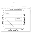
- FIG. 4 The relation of the rotational frequency of the high-speed shearing mixer and the unburned carbon of fly ash (product) and fly ash (product) remaining inside of a flotation tub is shown in Fig. 4. Showing this graph, without agitation (the rotational frequency of the high-speed shearing mixer is 0), the unburned carbon of fly ash (product) is 3 weight percent, but with the increase in the rotational frequency of the high-speed shearing mixer, the unburned carbon content of fly ash (product) falls, and the graph shows that the unburned carbon of the fly ash (product) reaches to 0.5 weight percent or less at about 750rpm in the rotational frequency of the high-speed shearing mixer.
- the slurry is supplied to a flotation machine, and 0.5mg of MIBC as a frother is added to the slurry to make the unburned carbon adhere to air bubbles and rise. These floating air bubbles are taken out as overflow. This process has been performed for 5 minutes.
- FIG. 1 A flowchart showing an embodiment of the method of removing unburned carbon from fly ash according to the present invention.
Landscapes
- Engineering & Computer Science (AREA)
- Chemical & Material Sciences (AREA)
- Environmental & Geological Engineering (AREA)
- Ceramic Engineering (AREA)
- Combustion & Propulsion (AREA)
- Civil Engineering (AREA)
- Materials Engineering (AREA)
- Structural Engineering (AREA)
- Organic Chemistry (AREA)
- Dispersion Chemistry (AREA)
- Processing Of Solid Wastes (AREA)
Abstract
Description
- The present invention relates to a method of removing unburned carbon from fly ash, and more particularly to a method of efficiently removing unburned carbon from the fly ash generated in coal firing power plants and so on and efficiently using the fly ash and the removed unburned carbon.
- Fly ash generated in coal firing power plants etc. is used for materials for cement and artificial lightweight aggregates, concrete admixture, etc. However, when fly ash is used as concrete admixture, unburned carbon of fly ash will absorb AE water reducing agent etc., and will reduce the workability of the concrete. And, at the time of placing of the concrete, unburned carbon comes floating and there is harmful influence of a black part occurring in the connecting portion of the concrete. Further, when there was much unburned carbon of fly ash, there was also a problem that the quality of an artificial lightweight aggregate deteriorated. Therefore, only fly ash with little unburned carbon was used for the materials of cement etc., the fly ash with high unburned carbon content could not be used effectively and was processed for reclamation as industrial waste.
- In order to solve such a problem, in the first patent document, a technology for removing unburned carbon of coal ash is disclosed. In this technology, after powdery coal ash is agitated and mixed with nonaqueous solvent of a low specific gravity rather than water and water, the mixture is settled and is separated into water layer including coal ash and nonaqueous solvent including unburned carbon.
- Further, the second patent document discloses a method of improving recovery rate and efficiently removing unburned carbon of coal ash by adding ionicity collector as a collector after adding acid to water slurry of coal ash in the process of coal ash processing with a hydrophobic process, in which collector is added to the water slurry of coal ash to make the unburned carbon hydrophobic, and flotation separation process, in which frother is added to the water slurry to generate air bubbles and the unburned carbon is adhered to the bubbles for flotation.
- Patent document 1: Japanese patent No.3060665 gazette
- Patent document 2: Japanese Patent Publication Heisei 8-252484 gazette
- However, since it is necessary by the method given in the above-mentioned
patent documents 1 to settle powdered coal ash after agitating mixture with the nonaqueous solvent of a low specific gravity rather than water and water, long time was needed for removal of the unburned carbon of coal ash, also after that, from the water layer containing coal ash and the nonaqueous solvent layer containing unburned carbon, each of coal ash and unburned carbon needed to be collected and there was a problem that the unburned carbon of coal ash was efficiently unremovable. - And, the method given in the
patent documents 2, in order to efficiently remove the unburned carbon of coal ash using flotation, the acid added to the water slurry of coal ash and the ionicity collector as a collector were needed, so that there was a problem that the cost required to remove the unburned carbon is increased. - The present invention has been made in consideration of the above problems, and the object thereof is to provide a method of efficiently removing unburned carbon from fly ash without special chemicals, and efficiently using fly ash and removed unburned carbon.
- To achieve the above object, the present invention is characterized in a method of removing unburned carbon from fly ash comprising the step of; adding water to fly ash to produce slurry; adding collector to the slurry; feeding the slurry and the collector to a submerged agitator having a rotation shaft penetrating a cylindrical main body in an axial direction thereof, plurality of chambers formed by dividing an inside of the main body in the axial direction thereof and an agitating vane fixed to the rotation shaft and rotating in each chamber, and adding shearing force to the slurry and collector; adding frother to the slurry and collector to which the sharing force is added; agitating the slurry and collector to generate air bubbles; and adhering unburned carbon of the fly ash to the air bubbles to rise the unburned carbon.
- With this invention, by adding shearing force to original fly ash slurry, which contains the unburned carbon and to which collector is added before flotation process, through a submerged agitator having a rotation shaft, which penetrates a cylindrical main body in the axial direction thereof, plurality of chambers divided and formed in the axial direction thereof in the inside of the main body, and an agitating vane, which is fixed to the rotation shaft and rotates in each chamber, each of the unburned carbon in slurry, true fly ash, and the collector can not only raise the distributed effect but transitionally generate activity energy (surface energy) on the surface of each distributed particle. In the process which makes this transitional surface energy calm down, the surface of unburned carbon particles, which becomes more oleophilicitized, and the surface of collector particles stick with each other, and mutual surface energy is lowered. The surface of true fly ash particles, which becomes more hydrophilicitized, adapts itself to water further, it distributes in water and the particles concerned lower the surface energy. As a result, the fly ash particles, to which the collector is adhered on the surface thereof and of which surface is modified, stably raise its oleophilicity and its flotation separation performance is raised in a latter flotation process, so that the fly ash particles distribute in water, and are efficiently separated with the true fly ash which becomes a flotation tailing. As a result, unburned carbon can efficiently be removed from the original fly ash slurry. When shearing force is not applied to the fly ash slurry and the collector and surface modification is not performed to the slurry and the collector, fly ash with 5.0% of unburned carbon can be reduced its unburned carbon content to only approximately 2%. On the other hand, by adding shearing force and performing surface modification, unburned carbon of the fly ash can considerably reduced, and fly ash with approximately 0.5% of unburned carbon can be obtained. In addition, in this case, generally used collector such as kerosene can be used, and a small amount (about 15%) is sufficient for the collector to the quantity of unburned carbon. This makes it possible to reduce the amount of collector used, to allow little kerosene etc. to remain in the fly ash as a product and to make post-processing after the flotation process easy.
- In applying shearing force through the submerged agitator to the slurry and the collector, it is preferred to apply 0.7 kWh/m3 or more and 10 kWh/m3 or less of agitation power per amount of unit quantity of slurry. If the agitation power does not reach 0.7 kWh/m3, shearing force applied to the slurry and the collector is inadequate and unburned carbon cannot be removed efficiently, but the agitation power exceeds 10 kWh/m3, the energy consumed to the removal efficiency of unburned carbon becomes excessive and is not preferred.
- The fly ash concentration of the slurry is preferably adjusted to be 3 weight percent or more and 50 weight percent or less. If the fly ash concentration is lower than 3 weight percent, it is not preferable since the quantity of slurry increases too much to the fly ash, which should be processed. On the contrary, if the fly ash concentration exceeds 50 weight percent, it is not desirable since it may not form slurry.
- It is preferred that the amount of the collector added is 5 weight percent or more and 100 weight percent or less of the amount of unburned carbon. When the amount of the collector added is less than 5 weight percent, the effect of adsorbing unburned carbon of fly ash falls and flotation separation performance cannot be raised, and when the amount of the collector added exceeds 100 weight percent of the amount of unburned carbon of fly ash, the effect as a collector may approach a limit, even if it makes the amount of addition increase, the cost of a collector only increases and it is not desirable.
- Water of the fly ash slurry after flotation separation is separated with a solid/liquid separator and can be reused to add to new fly ash slurry, and/or can be reused to erase bubbles when adhering unburned carbon to air bubbles, which lessens drainage out of the system as little as possible.
- The unburned carbon of the fly ash that was separated through flotation can be used as fuel. The utilization of the unburned carbon as fuel allows kerosene or the like used as a collector to efficiently be burned simultaneously.
- The unburned carbon of the fly ash, which was separated through flotation, can be made into 1 weight percent or less, and it can be use as a mixing material for cement. This can suppress absorption of AE water reducing agent by unburned carbon etc. to the minimum and can prevent the fall of the workability of concrete. Moreover, it can also prevent floating up of the unburned carbon at the time of placing concrete, and a black part generated in the connecting portion of the concrete.
- The unburned carbon of the fly ash, which was separated through flotation, can be made into 1 weight percent or less, and it can be used as a material for lightweight aggregate. This makes it possible to produce precise lightweight artificial aggregate of high strength.
- As described above, according to this invention, it is offered a method of removing unburned carbon from fly ash which can mechanically and efficiently remove unburned carbon even if it does not use special chemicals etc., and can use fly ash and the removed unburned carbon effectively.
- Figure 1 shows an example of the system composition for enforcing a method of removing an unburned carbon from fly ash according to the present invention, and the system roughly comprises a
slurry tank 2 for adding water to fly ash to generate slurry, a submerged agitator 4 which applies shearing force to the slurry and a collector after adding the collector to slurry to modify the surface of unburned carbon, aflotation machine 11 which separates the unburned carbon by adding a frother to the slurry, generating air bubbles, making the unburned carbon of fly ash adhere to these air bubbles, and making it rise, a solid/liquid separator 13 which carries out solid/liquid separation of the tailing from theflotation machine 11, adrier 14 for obtaining fly ash (product) which is made to dry the cake from solid/liquid separator 13, afilter press 18 for solid/liquid separating the froth fromflotation machine 11 to obtain unburned carbon and so on. - The
slurry tank 2 is installed to produce slurry with adding water and fly ash, and is provided with an agitating vane to agitate the slurry therein. At the upper stage of theslurry tank 2, afly ash tank 1 and water supply equipment are installed, and apump 3 is arranged to send slurry to the submerged agitator 4 at the down stage of theslurry tank 2. - The submerged agitator 4 is installed to add shearing force to the slurry and the collector and to modify the surface of the unburned carbon. As an example of the submerged agitator 4, there is a high-
speed shearing mixer 20 shown in Fig. 2. The high-speed shearing mixer 20 is provided with a cylindricalmain body 20a, plurality of partition walls 20c which dividemain body 20a into plurality of chambers, and plurality of agitating vanes 20e radially fixed to arotation shaft 20d, and therotation shaft 20d and the agitating vanes 20e rotate through amotor 21 and areduction gear 22. As shown in Fig. 1, a kerosene tank 6, which stores kerosene as a collector, and apump 5 for supplying the kerosene to the submerged agitator 4, are installed in the upper stage of the submerged agitator 4. - An adjustment tub 7 is installed to add frother supplied through a
pump 8 from afrother tank 9 to the slurry and the collector from the submerged agitator 4, and to mix those with each other. The adjustment tub 7 is provided with an agitating vane therein. At the down stage of the adjustment tub 7, apump 10 is arranged to send the slurry to theflotation machine 11. - The
flotation machine 11 is installed to make the unburned carbon of fly ash adhere to air bubbles, to separate into unburned carbon and the fly ash from which unburned carbon was removed. Above theflotation machine 11, an air supplying equipment is installed to generate air bubbles. At the rear stage of theflotation machine 11, apump 12 is arranged to send tailing to the solid/liquid separator 13. - The solid/
liquid separator 13 is installed to solid/liquid separate the tailing containing the fly ash discharged from theflotation machine 11 and to divide the tailing into cake and water. - The
drier 14 is installed to dry the cake supplied from the solid/liquid separator 13 with hot wind from ahot blast stove 16, and the dried cake, that is fly ash as product is used as a cement mixing material etc. - A
bag filter 15 is installed to collect fine dust from thedrier 14, and the collected fine dust is also used as a cement mixing material etc. - The
filter press 18 is installed to solid/liquid separate the froth containing the unburned carbon from theflotation machine 11, and the unburned carbon contained in the separated cake can be used as a fuel. Water discharged from thefilter press 18 can be reused in theslurry tank 2 etc. through apump 17. - The
hot blast stove 16 is installed to generates hot wind by using the unburned carbon discharged from thefilter press 18 as fuel, and the hot wind is used indrier 14. - Next, a method of removing unburned carbon from fly ash with the above-mentioned system according to the present invention will be explained with reference to Fig. 1 as a main drawing.
- Fly ash is supplied to the
slurry tank 2 from theslurry tank 1 and is mixed with water to produce slurry. Here, the fly ash concentration in slurry is adjusted in the range from 3 to 50 weight percent. - Next, the slurry containing fly ash in the
slurry tank 2 is supplied to the submerged agitator 4 through thepump 3. On the other hand, kerosene as a collector is supplied to the submerged agitator 4 through thepump 5 from the kerosene tank 6. Other than kerosene, generally used collectors such as light oil and heavy oil can be used. The amount of the collector added is adjusted from 5 to 100 weight percent of the amount of unburned carbon of fly ash. - Next, to the slurry and the collector is added shearing force in the submerged agitator 4. The adding process of this shearing force is a characterizing portion of this invention. For example, adding of shearing force can be performed using the high-
speed shearing mixer 20 shown in Fig. 2. In the high-speed shearing mixer 20, shearing force is added to the slurry and the collector supplied from the entrance 20f is added through rotating agitating vane 20e in each chamber divided from the partition walls 20c. With the partition walls 20c, the short pass of slurry can be prevented and shearing force can be added to the slurry and collector certainly. The slurry and the collector, to which shearing force is added, are discharged from theexit 20b, and are supplied to the adjustment tub 7. - As described above, adding of shearing force to the fly ash slurry and the collector is for rise of flotation separation performance by modifying the surface of unburned carbon, this point will be explained in detail referring to Fig.3.
- Only by mixing the collector to the slurry containing fly ash, as shown in Fig.3(a), it is only in the state where coal ash, unburned carbon and the collector are respectively and separately mixed in water. Even if the slurry is supplied to flotation machine in such state, there is little quantity of the unburned carbon that adheres to air bubbles together with the collector. Therefore, the unburned carbon of fly ash is efficiently unremovable with flotation separation.
- On the other hand, as shown in Fig. 3(a), when shearing force is added to the slurry and the collector to modify the surfaces thereof, as shown in Fig.3(b), unburned carbon is adsorbed to the collector. Then, when performing flotation separation with a flotation machine, as shown in Fig. 3(c), the unburned carbon adsorbed to the collector is adhered to air bubbles and rises together with the bubbles. Thus, the flotation separation performance of the unburned carbon can be improved. Meanwhile, when applying shearing force to the slurry and the collector through the high-
speed shearing mixer 20, 0.7-10kWh/m3 more preferably 0.9-1.8kWh/m3 of agitating force per unit quantity of slurry is added. - Next, as illustrated in Fig. 1, the froth containing the unburned carbon discharged from the
flotation machine 11 is solid/liquid separated by thefilter press 18 to collect unburned carbon. Water departed from thefilter press 18 can be supplied to theslurry tank 2 through thepump 17 to add to new fly ash, or can be reused for erasing bubbles at the time of making unburned carbon adhere to air bubbles in theflotation machine 11. - On the other hand, the tailing containing the fly ash from the
flotation machine 11 is solid/liquid separated by the solid/liquid separator 13, when much water is contained in the cake, with the hot wind obtained by burning the unburned carbon discharged from thefilter press 18 in thehot blast stove 16, the cake is dried in drier 14, and fly ash as product becoming 1 weight percent or less can be used as cement mixing material etc. Further, the fine dust collected by thebag filter 15 can also be used as cement mixing material etc. - 1000ml of water and 200g of fly ash (containing 5.0 weight percent of unburned carbon) are mixed while being agitated to produce slurry. To the slurry is added kerosene in the range of 0.6-8.0ml and is agitated at 0-1164rpm by the high-speed shearing mixer showing in Fig.2 to add shearing force to the slurry and the kerosene, and unburned carbon of the fly ash is made to be hydrophobic.
- After the process of hydrophobic, the slurry is supplied to a flotation machine, and 0.5mg of MIBC (methyl isobutyl carbinol) as a frother is added to the slurry to make the unburned carbon adhere to air bubbles and rise. These floating air bubbles are taken out as overflow. This process has been performed for 5 minutes.
- The relation of the rotational frequency of the high-speed shearing mixer and the unburned carbon of fly ash (product) and fly ash (product) remaining inside of a flotation tub is shown in Fig. 4. Showing this graph, without agitation (the rotational frequency of the high-speed shearing mixer is 0), the unburned carbon of fly ash (product) is 3 weight percent, but with the increase in the rotational frequency of the high-speed shearing mixer, the unburned carbon content of fly ash (product) falls, and the graph shows that the unburned carbon of the fly ash (product) reaches to 0.5 weight percent or less at about 750rpm in the rotational frequency of the high-speed shearing mixer.
- 1000ml of water and 200g of fly ash (containing 5.0 weight percent of unburned carbon) are mixed while being agitated to produce slurry. To the slurry is added kerosene in the range of 0.6-8.0ml and is agitated at 873rpm by the high-speed shearing mixer showing in Fig.2 to add shearing force to the slurry and the kerosene, and unburned carbon of the fly ash is made to be hydrophobic.
- After the process of hydrophobic, the slurry is supplied to a flotation machine, and 0.5mg of MIBC as a frother is added to the slurry to make the unburned carbon adhere to air bubbles and rise. These floating air bubbles are taken out as overflow. This process has been performed for 5 minutes.
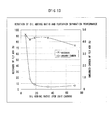
- The relation of the amount of kerosene added and the unburned carbon of fly ash (product) and fly ash (product) remaining inside of a flotation tub that is shown in Fig. 5. This graph shows that the unburned carbon of fly ash (product) reaches to 0.5% or less in the oil-adding ratio of about 15% to unburned carbon.
- [Figure 1]
A flowchart showing an embodiment of the method of removing unburned carbon from fly ash according to the present invention. - [Figure 2]
A fracture schematic diagram in part showing an embodiment for a high-speed shearing mixer as a submerged agitator of the system shown in Fig. 1. - [Figure 3]
Drawings for explaining the effect of the surface modification of unburned carbon, in which (a) is a schematic diagram showing the state before the surface modification, (b) the state after the surface modification and (c) the state in a flotation process. - [Figure 4]
A graph showing the relation of flotation separation performance and rotational frequency of high-speed sharing mixer in theEmbodiment 1 of the present invention. - [Figure 5]
A graph showing the relation of flotation separation performance and oil adding ration in theEmbodiment 2 of the present invention. -
- 1
- Fly ash tank
- 2
- Slurry tank
- 3
- Pump
- 4
- Submerged agitator
- 5
- Pump
- 6
- Kerosene tank
- 7
- Adjustment tub
- 8
- Pump
- 9
- Frother tank
- 10
- Pump
- 11
- Flotation machine
- 12
- Pump
- 13
- Solid/liquid separator
- 14
- Drier
- 15
- Bag filter
- 16
- Hot blast stove
- 17
- Pump
- 18
- Filter press
- 20
- High-speed shearing mixer
- 20a
- Main body
- 20b
- Exit
- 20c
- Partition wall
- 20d
- Rotation shaft
- 20e
- Agitating vane
- 20f
- Entrance
- 21
- Motor
- 22
- Reduction gear
Claims (8)
- A method of removing unburned carbon from fly ash comprising the steps of:adding water to fly ash to produce slurry;adding collector to said slurry;feeding said slurry and collector to a submerged agitator having a rotation shaft penetrating a cylindrical main body in an axial direction thereof, plurality of chambers formed by dividing an inside of the main body in the axial direction thereof and an agitating vane fixed to the rotation shaft and rotating in each chamber, and adding shearing force to said slurry and collector;adding frother to said slurry and collector to which the sharing force is added;agitating said slurry and collector to generate air bubbles; andadhering unburned carbon of said fly ash to the air bubbles to rise said unburned carbon.
- The method of removing unburned carbon from fly ash as claimed in claim 1,wherein said agitating force when the submerged agitator add sharing force to said slurry and said collector is 0.7 kWh/m3 or more and 10 kWh/m3 or less per unit quantity of slurry.
- The method of removing unburned carbon from fly ash as claimed in claim 1 or 2, wherein concentration of said fly ash in the slurry is 3 weight percent or more and 50 weight percent or less.
- The method of removing unburned carbon from fly ash as claimed in claim 1, 2 or 3, wherein amount of said collector added is 5 weight percent or more, and 100 weight percent or less of amount of said unburned carbon of said fly ash.
- The method of removing unburned carbon from fly ash as claimed in one of claims 1 to 4, further comprising the steps of separating with a solid/liquid separation device water of fly ash slurry that is separated through flotation, and water separated is added to new fly ash or/and the water is used to erase bubbles when adhering unburned carbon to air bubbles, for purpose of reuse.
- The method of removing unburned carbon from fly ash as claimed in one of claims 1 to 5, wherein said unburned carbon of said fly ash separated through flotation is used as fuel.
- The method of removing unburned carbon from fly ash as claimed in one of claims 1 to 6, wherein said unburned carbon content in said fly ash separated through flotation is 1 weight percent or less and is used as a mixing material for cement.
- The method of removing unburned carbon from fly ash as claimed one of claims 1 to 6, wherein said unburned carbon content of fly ash separated through flotation is 1 weight percent or less and used as a material for manufacturing lightweight aggregate.
Applications Claiming Priority (2)
| Application Number | Priority Date | Filing Date | Title |
|---|---|---|---|
| JP2003350449A JP3613347B1 (en) | 2003-10-09 | 2003-10-09 | How to remove unburned carbon in fly ash |
| PCT/JP2004/014819 WO2005035134A1 (en) | 2003-10-09 | 2004-10-07 | Method of removing unburned carbon from fly ash |
Publications (3)
| Publication Number | Publication Date |
|---|---|
| EP1685907A1 true EP1685907A1 (en) | 2006-08-02 |
| EP1685907A4 EP1685907A4 (en) | 2008-10-22 |
| EP1685907B1 EP1685907B1 (en) | 2015-12-23 |
Family
ID=34191605
Family Applications (1)
| Application Number | Title | Priority Date | Filing Date |
|---|---|---|---|
| EP04792117.6A Expired - Lifetime EP1685907B1 (en) | 2003-10-09 | 2004-10-07 | Method of removing unburned carbon from fly ash |
Country Status (10)
| Country | Link |
|---|---|
| US (1) | US8551223B2 (en) |
| EP (1) | EP1685907B1 (en) |
| JP (1) | JP3613347B1 (en) |
| KR (1) | KR101123662B1 (en) |
| CN (1) | CN100455357C (en) |
| DK (1) | DK1685907T3 (en) |
| ES (1) | ES2561130T3 (en) |
| RU (1) | RU2343984C2 (en) |
| TW (1) | TWI243711B (en) |
| WO (1) | WO2005035134A1 (en) |
Cited By (3)
| Publication number | Priority date | Publication date | Assignee | Title |
|---|---|---|---|---|
| CN101797575A (en) * | 2010-03-09 | 2010-08-11 | 天津城市建设学院 | Flyash treatment method for waste incineration |
| EP1970125A4 (en) * | 2005-12-22 | 2011-08-17 | Mitsui Shipbuilding Eng | METHOD FOR REMOVING CARBON DAMAGED FROM VOLATILE ASHES |
| EP2116308A4 (en) * | 2006-12-26 | 2012-01-18 | Mitsui Shipbuilding Eng | Apparatus for removing unburned carbon in fly ash |
Families Citing this family (32)
| Publication number | Priority date | Publication date | Assignee | Title |
|---|---|---|---|---|
| JP2007054773A (en) * | 2005-08-26 | 2007-03-08 | Mitsui Eng & Shipbuild Co Ltd | Method for removing unburned carbon from coal ash |
| JP4751139B2 (en) * | 2005-08-26 | 2011-08-17 | 三井造船株式会社 | Equipment for removing unburned carbon in fly ash |
| EP1944278A4 (en) * | 2005-10-31 | 2013-12-25 | Taiheiyo Cement Corp | Apparatus for adding wet ash to cement and addition method |
| TW200730251A (en) * | 2005-12-07 | 2007-08-16 | Mitsui Shipbuilding Eng | Apparatus and method for removing unburned carbon from fly ash |
| JP4917309B2 (en) * | 2005-12-26 | 2012-04-18 | 三井造船株式会社 | How to remove unburned carbon in fly ash |
| JP4859459B2 (en) | 2005-12-29 | 2012-01-25 | 三井造船株式会社 | How to remove unburned carbon in fly ash |
| CN100586590C (en) * | 2006-11-16 | 2010-02-03 | 廖昌禧 | Coal ash recycling treatment method |
| JP5270370B2 (en) * | 2006-12-05 | 2013-08-21 | 太平洋セメント株式会社 | Cement manufacturing apparatus and manufacturing method |
| CN101583578A (en) * | 2006-12-05 | 2009-11-18 | 太平洋水泥株式会社 | Method and apparatus for treating coal ash |
| CN101547754B (en) * | 2006-12-11 | 2012-04-25 | 三井造船株式会社 | Method of removing unburned carbon from coal ash |
| JP5301189B2 (en) * | 2008-03-31 | 2013-09-25 | 太平洋セメント株式会社 | Chemical management method in wet decarburization of fly ash |
| JP5319973B2 (en) * | 2008-07-08 | 2013-10-16 | 三井造船株式会社 | Method and apparatus for removing unburned carbon in fly ash |
| JP2010017619A (en) * | 2008-07-08 | 2010-01-28 | Mitsui Eng & Shipbuild Co Ltd | Method of separating unburned carbon in fly ash |
| EP2347998B1 (en) * | 2008-11-12 | 2019-10-16 | Taiheiyo Cement Corporation | Apparatus and process for producing industrial salt |
| JP2010227769A (en) * | 2009-03-26 | 2010-10-14 | Taiheiyo Cement Corp | Apparatus and method for producing modified ash |
| JP5393220B2 (en) * | 2009-03-27 | 2014-01-22 | 太平洋セメント株式会社 | Method and system for removing impurities from limestone |
| JP5562057B2 (en) * | 2010-02-04 | 2014-07-30 | 太平洋セメント株式会社 | Method and apparatus for removing unburned carbon in fly ash |
| FI124422B (en) * | 2011-03-14 | 2014-08-29 | Valmet Power Oy | Process for ash treatment and ash treatment plant |
| RU2500480C2 (en) * | 2012-02-20 | 2013-12-10 | Федеральное государственное бюджетное образовательное учреждение высшего профессионального образования "Иркутский государственный технический университет" (ФГБОУ ВПО "ИрГТУ") | Method for extraction of nano-sized particles from man-made wastes by flotation |
| JP6157057B2 (en) * | 2012-03-23 | 2017-07-05 | 太平洋セメント株式会社 | How to treat fly ash |
| JP5989480B2 (en) * | 2012-09-21 | 2016-09-07 | 太平洋セメント株式会社 | Production method of adsorbent |
| JP6061289B2 (en) * | 2012-10-31 | 2017-01-18 | 太平洋セメント株式会社 | Construction material manufacturing apparatus and manufacturing method |
| WO2014112222A1 (en) * | 2013-01-16 | 2014-07-24 | 太平洋セメント株式会社 | Use method for byproduct ash from blast furnace |
| JP2015199006A (en) * | 2014-04-04 | 2015-11-12 | 松藤 泰典 | Production method and production facility of fly ash powder |
| JP2015199005A (en) * | 2014-04-04 | 2015-11-12 | 松藤 泰典 | Method and apparatus for production of concentrated fly ash slurry |
| CN105149101B (en) * | 2015-10-26 | 2018-03-09 | 天津城建大学 | A kind of processing method of the step flotation of medical refuse burning flyash two |
| CN107309239A (en) * | 2017-05-18 | 2017-11-03 | 潍坊鑫山环保重工科技有限公司 | A kind of coal ash separation method of coal chemical industry gasifier slag |
| US20210032163A1 (en) * | 2018-03-19 | 2021-02-04 | Tokuyama Corporation | Process for reforming the fly ash |
| RU2692334C1 (en) * | 2018-04-27 | 2019-06-24 | Федеральное государственное бюджетное учреждение науки Объединенный институт высоких температур Российской академии наук (ОИВТ РАН) | Method of extracting unburned carbon from tpp fly ash |
| JP7372829B2 (en) * | 2019-12-18 | 2023-11-01 | 株式会社トクヤマ | Method for producing modified fly ash |
| JP7534174B2 (en) | 2020-09-30 | 2024-08-14 | 株式会社トクヤマ | Method for determining manufacturing conditions for modified fly ash and manufacturing method thereof |
| CN112237786B (en) * | 2020-10-14 | 2022-02-22 | 华东理工大学 | Method for separating residual carbon from coal gasification fine slag |
Family Cites Families (28)
| Publication number | Priority date | Publication date | Assignee | Title |
|---|---|---|---|---|
| US2142207A (en) * | 1935-10-29 | 1939-01-03 | Colorado Fuel & Iron Corp | Flotation process |
| US4483624A (en) * | 1982-08-25 | 1984-11-20 | Freeport Kaolin Company | High intensity conditioning mill and method |
| SU1176952A1 (en) * | 1984-03-26 | 1985-09-07 | Научно-Исследовательская Лаборатория Физико-Химической Механики Материалов И Технологических Процессов Ордена Ленина Главмоспромстройматериалов | Method of extraction of unburnt fuel from ash |
| JPS6125651A (en) | 1984-07-17 | 1986-02-04 | Mitsui Eng & Shipbuild Co Ltd | Floating and recovering method of pulverized coal |
| SU1321469A1 (en) * | 1984-10-22 | 1987-07-07 | Днепропетровский горный институт им.Артема | Method of separating coal-containing product |
| JPS61103992A (en) | 1984-10-26 | 1986-05-22 | Tokyo Electric Power Co Inc:The | Deashing recovery of coal |
| JPS61106698A (en) | 1984-10-31 | 1986-05-24 | Mitsui Eng & Shipbuild Co Ltd | Recovery of finely granulated coal by cyclone |
| JPS63143928A (en) * | 1986-12-08 | 1988-06-16 | Mitsui Eng & Shipbuild Co Ltd | Solid and fluid blending device |
| SU1717238A1 (en) * | 1988-03-09 | 1992-03-07 | Уральский филиал Всесоюзного научно-исследовательского и проектного института галургии | Suspension conditioner |
| CN1036342A (en) * | 1988-07-18 | 1989-10-18 | 福建省沙县园木厂 | Classification of hollow glass corpuscles from powder coal ash |
| US5066388A (en) * | 1990-02-27 | 1991-11-19 | Lena Ross | Process and apparatus for disengaging and separating bitumen from pulverized tar sands using selective cohesion |
| JPH044032A (en) | 1990-04-20 | 1992-01-08 | Hitachi Ltd | Sealing device for continuous vacuum treating device |
| JPH0583468A (en) | 1991-09-25 | 1993-04-02 | Rohm Co Ltd | Image sensor |
| JP3243568B2 (en) | 1991-08-07 | 2002-01-07 | 太平洋セメント株式会社 | Processing method of coal ash |
| JP3060665B2 (en) | 1991-11-18 | 2000-07-10 | 三菱マテリアル株式会社 | Removal method of unburned carbon in coal ash |
| CN1098425A (en) * | 1993-08-04 | 1995-02-08 | 邓端云 | Utilize coal ash to produce the method for carbon black and white carbon black |
| JP3411649B2 (en) * | 1993-11-22 | 2003-06-03 | 太平洋セメント株式会社 | Processing method of coal ash |
| JP3411651B2 (en) * | 1993-12-24 | 2003-06-03 | 太平洋セメント株式会社 | Processing method of coal ash |
| JP3580868B2 (en) | 1994-08-18 | 2004-10-27 | 太平洋セメント株式会社 | Coal ash treatment method |
| JP3505000B2 (en) * | 1995-03-17 | 2004-03-08 | 太平洋セメント株式会社 | Coal ash treatment method |
| JPH09225441A (en) | 1996-02-26 | 1997-09-02 | Chichibu Onoda Cement Corp | Processing method of fly ash and its applications |
| DE19810650A1 (en) * | 1998-03-12 | 1999-09-23 | Fan Separator Gmbh | Removal of small particles from process water |
| WO2000002662A1 (en) * | 1998-07-13 | 2000-01-20 | Board Of Control For Michigan Technological University | Method of removing carbon from fly ash |
| US6126014A (en) * | 1998-09-29 | 2000-10-03 | The United States Of America As Represented By The Department Of Energy | Continuous air agglomeration method for high carbon fly ash beneficiation |
| US5936216A (en) * | 1998-12-01 | 1999-08-10 | Wu; Chiung-Hsin | Froth floatation process for separating carbon from coal ash |
| JP4346299B2 (en) | 2002-10-25 | 2009-10-21 | 三井造船株式会社 | Pulverized coal flotation method, pulverized coal surface reformer, and pulverized coal flotation system |
| JP2003284973A (en) | 2003-01-24 | 2003-10-07 | Taiheiyo Cement Corp | Coal ash treatment method |
| JP3581707B2 (en) | 2003-01-24 | 2004-10-27 | 太平洋セメント株式会社 | Coal ash treatment method |
-
2003
- 2003-10-09 JP JP2003350449A patent/JP3613347B1/en not_active Expired - Lifetime
-
2004
- 2004-10-07 KR KR1020067006553A patent/KR101123662B1/en not_active Expired - Fee Related
- 2004-10-07 CN CNB2004800294298A patent/CN100455357C/en not_active Expired - Lifetime
- 2004-10-07 DK DK04792117.6T patent/DK1685907T3/en active
- 2004-10-07 EP EP04792117.6A patent/EP1685907B1/en not_active Expired - Lifetime
- 2004-10-07 RU RU2006115700A patent/RU2343984C2/en not_active IP Right Cessation
- 2004-10-07 WO PCT/JP2004/014819 patent/WO2005035134A1/en not_active Ceased
- 2004-10-07 US US10/574,762 patent/US8551223B2/en not_active Expired - Fee Related
- 2004-10-07 ES ES04792117.6T patent/ES2561130T3/en not_active Expired - Lifetime
- 2004-10-08 TW TW93130586A patent/TWI243711B/en not_active IP Right Cessation
Cited By (3)
| Publication number | Priority date | Publication date | Assignee | Title |
|---|---|---|---|---|
| EP1970125A4 (en) * | 2005-12-22 | 2011-08-17 | Mitsui Shipbuilding Eng | METHOD FOR REMOVING CARBON DAMAGED FROM VOLATILE ASHES |
| EP2116308A4 (en) * | 2006-12-26 | 2012-01-18 | Mitsui Shipbuilding Eng | Apparatus for removing unburned carbon in fly ash |
| CN101797575A (en) * | 2010-03-09 | 2010-08-11 | 天津城市建设学院 | Flyash treatment method for waste incineration |
Also Published As
| Publication number | Publication date |
|---|---|
| KR101123662B1 (en) | 2012-03-20 |
| JP2007007485A (en) | 2007-01-18 |
| DK1685907T3 (en) | 2016-03-14 |
| US8551223B2 (en) | 2013-10-08 |
| TW200517185A (en) | 2005-06-01 |
| ES2561130T3 (en) | 2016-02-24 |
| WO2005035134A1 (en) | 2005-04-21 |
| EP1685907B1 (en) | 2015-12-23 |
| EP1685907A4 (en) | 2008-10-22 |
| CN100455357C (en) | 2009-01-28 |
| US20070199486A1 (en) | 2007-08-30 |
| RU2006115700A (en) | 2007-11-27 |
| TWI243711B (en) | 2005-11-21 |
| RU2343984C2 (en) | 2009-01-20 |
| KR20060120003A (en) | 2006-11-24 |
| JP3613347B1 (en) | 2005-01-26 |
| CN1863604A (en) | 2006-11-15 |
Similar Documents
| Publication | Publication Date | Title |
|---|---|---|
| US8551223B2 (en) | Method of removing unburned carbon from fly ash | |
| US8051985B2 (en) | Method of removing unburned carbon from coal ash | |
| US8893892B2 (en) | Apparatus and method for removing unburned carbon from fly ash | |
| JP2007054773A (en) | Method for removing unburned carbon from coal ash | |
| US7993450B2 (en) | Method for removal of unburned carbon in fly ash | |
| US7918344B2 (en) | Method for removal of unburned carbon from fly ash | |
| US7703610B2 (en) | Method for removal of unburned carbon contained in fly ash | |
| CN101185933A (en) | Coal ash recycling treatment method | |
| HK1098099A (en) | Method of removing unburned carbon from fly ash | |
| JP4751139B2 (en) | Equipment for removing unburned carbon in fly ash | |
| HK1126160B (en) | Method for removal of unburned carbon contained fly ash |
Legal Events
| Date | Code | Title | Description |
|---|---|---|---|
| PUAI | Public reference made under article 153(3) epc to a published international application that has entered the european phase |
Free format text: ORIGINAL CODE: 0009012 |
|
| 17P | Request for examination filed |
Effective date: 20060419 |
|
| AK | Designated contracting states |
Kind code of ref document: A1 Designated state(s): AT BE BG CH CY CZ DE DK EE ES FI FR GB GR HU IE IT LI LU MC NL PL PT RO SE SI SK TR |
|
| DAX | Request for extension of the european patent (deleted) | ||
| REG | Reference to a national code |
Ref country code: HK Ref legal event code: DE Ref document number: 1098099 Country of ref document: HK |
|
| RIC1 | Information provided on ipc code assigned before grant |
Ipc: B03D 103/08 20060101ALN20080910BHEP Ipc: B03D 1/02 20060101AFI20050425BHEP Ipc: C04B 7/36 20060101ALI20080910BHEP |
|
| A4 | Supplementary search report drawn up and despatched |
Effective date: 20080918 |
|
| 17Q | First examination report despatched |
Effective date: 20110713 |
|
| GRAP | Despatch of communication of intention to grant a patent |
Free format text: ORIGINAL CODE: EPIDOSNIGR1 |
|
| RAP1 | Party data changed (applicant data changed or rights of an application transferred) |
Owner name: MITSUI ENGINEERING & SHIPBUILDING CO., LTD. Owner name: TAIHEIYO CEMENT CORPORATION |
|
| RIN1 | Information on inventor provided before grant (corrected) |
Inventor name: ABE, KAZUO, MITSUI ENGINEERING & SHIPBUILDING CO., Inventor name: MURATA, TOSHIAKI, MITSUI ENGINEERING & SHIPBUILDIN Inventor name: SAITO, SHINICHIRO, TAIHEIYO CEMENT CORPORATION Inventor name: KIMOTO, KOSUKE, MITSUI ENGINEERING & SHIPBUILDING |
|
| INTG | Intention to grant announced |
Effective date: 20150805 |
|
| GRAS | Grant fee paid |
Free format text: ORIGINAL CODE: EPIDOSNIGR3 |
|
| RAP1 | Party data changed (applicant data changed or rights of an application transferred) |
Owner name: TAIHEIYO CEMENT CORPORATION |
|
| GRAA | (expected) grant |
Free format text: ORIGINAL CODE: 0009210 |
|
| AK | Designated contracting states |
Kind code of ref document: B1 Designated state(s): AT BE BG CH CY CZ DE DK EE ES FI FR GB GR HU IE IT LI LU MC NL PL PT RO SE SI SK TR |
|
| REG | Reference to a national code |
Ref country code: GB Ref legal event code: FG4D |
|
| REG | Reference to a national code |
Ref country code: CH Ref legal event code: EP |
|
| REG | Reference to a national code |
Ref country code: IE Ref legal event code: FG4D |
|
| REG | Reference to a national code |
Ref country code: AT Ref legal event code: REF Ref document number: 766294 Country of ref document: AT Kind code of ref document: T Effective date: 20160115 |
|
| REG | Reference to a national code |
Ref country code: DE Ref legal event code: R096 Ref document number: 602004048401 Country of ref document: DE |
|
| REG | Reference to a national code |
Ref country code: ES Ref legal event code: FG2A Ref document number: 2561130 Country of ref document: ES Kind code of ref document: T3 Effective date: 20160224 |
|
| REG | Reference to a national code |
Ref country code: CH Ref legal event code: NV Representative=s name: HEPP WENGER RYFFEL AG, CH |
|
| REG | Reference to a national code |
Ref country code: DK Ref legal event code: T3 Effective date: 20160307 |
|
| REG | Reference to a national code |
Ref country code: NL Ref legal event code: MP Effective date: 20151223 |
|
| REG | Reference to a national code |
Ref country code: AT Ref legal event code: MK05 Ref document number: 766294 Country of ref document: AT Kind code of ref document: T Effective date: 20151223 |
|
| PG25 | Lapsed in a contracting state [announced via postgrant information from national office to epo] |
Ref country code: SE Free format text: LAPSE BECAUSE OF FAILURE TO SUBMIT A TRANSLATION OF THE DESCRIPTION OR TO PAY THE FEE WITHIN THE PRESCRIBED TIME-LIMIT Effective date: 20151223 Ref country code: NL Free format text: LAPSE BECAUSE OF FAILURE TO SUBMIT A TRANSLATION OF THE DESCRIPTION OR TO PAY THE FEE WITHIN THE PRESCRIBED TIME-LIMIT Effective date: 20151223 Ref country code: GR Free format text: LAPSE BECAUSE OF FAILURE TO SUBMIT A TRANSLATION OF THE DESCRIPTION OR TO PAY THE FEE WITHIN THE PRESCRIBED TIME-LIMIT Effective date: 20160324 Ref country code: FI Free format text: LAPSE BECAUSE OF FAILURE TO SUBMIT A TRANSLATION OF THE DESCRIPTION OR TO PAY THE FEE WITHIN THE PRESCRIBED TIME-LIMIT Effective date: 20151223 |
|
| PG25 | Lapsed in a contracting state [announced via postgrant information from national office to epo] |
Ref country code: CZ Free format text: LAPSE BECAUSE OF FAILURE TO SUBMIT A TRANSLATION OF THE DESCRIPTION OR TO PAY THE FEE WITHIN THE PRESCRIBED TIME-LIMIT Effective date: 20151223 Ref country code: IT Free format text: LAPSE BECAUSE OF FAILURE TO SUBMIT A TRANSLATION OF THE DESCRIPTION OR TO PAY THE FEE WITHIN THE PRESCRIBED TIME-LIMIT Effective date: 20151223 |
|
| PG25 | Lapsed in a contracting state [announced via postgrant information from national office to epo] |
Ref country code: SK Free format text: LAPSE BECAUSE OF FAILURE TO SUBMIT A TRANSLATION OF THE DESCRIPTION OR TO PAY THE FEE WITHIN THE PRESCRIBED TIME-LIMIT Effective date: 20151223 Ref country code: PL Free format text: LAPSE BECAUSE OF FAILURE TO SUBMIT A TRANSLATION OF THE DESCRIPTION OR TO PAY THE FEE WITHIN THE PRESCRIBED TIME-LIMIT Effective date: 20151223 Ref country code: PT Free format text: LAPSE BECAUSE OF FAILURE TO SUBMIT A TRANSLATION OF THE DESCRIPTION OR TO PAY THE FEE WITHIN THE PRESCRIBED TIME-LIMIT Effective date: 20160426 Ref country code: EE Free format text: LAPSE BECAUSE OF FAILURE TO SUBMIT A TRANSLATION OF THE DESCRIPTION OR TO PAY THE FEE WITHIN THE PRESCRIBED TIME-LIMIT Effective date: 20151223 Ref country code: RO Free format text: LAPSE BECAUSE OF FAILURE TO SUBMIT A TRANSLATION OF THE DESCRIPTION OR TO PAY THE FEE WITHIN THE PRESCRIBED TIME-LIMIT Effective date: 20151223 Ref country code: AT Free format text: LAPSE BECAUSE OF FAILURE TO SUBMIT A TRANSLATION OF THE DESCRIPTION OR TO PAY THE FEE WITHIN THE PRESCRIBED TIME-LIMIT Effective date: 20151223 |
|
| REG | Reference to a national code |
Ref country code: DE Ref legal event code: R097 Ref document number: 602004048401 Country of ref document: DE |
|
| PLBE | No opposition filed within time limit |
Free format text: ORIGINAL CODE: 0009261 |
|
| STAA | Information on the status of an ep patent application or granted ep patent |
Free format text: STATUS: NO OPPOSITION FILED WITHIN TIME LIMIT |
|
| 26N | No opposition filed |
Effective date: 20160926 |
|
| PG25 | Lapsed in a contracting state [announced via postgrant information from national office to epo] |
Ref country code: BE Free format text: LAPSE BECAUSE OF FAILURE TO SUBMIT A TRANSLATION OF THE DESCRIPTION OR TO PAY THE FEE WITHIN THE PRESCRIBED TIME-LIMIT Effective date: 20151223 |
|
| PG25 | Lapsed in a contracting state [announced via postgrant information from national office to epo] |
Ref country code: SI Free format text: LAPSE BECAUSE OF FAILURE TO SUBMIT A TRANSLATION OF THE DESCRIPTION OR TO PAY THE FEE WITHIN THE PRESCRIBED TIME-LIMIT Effective date: 20151223 |
|
| REG | Reference to a national code |
Ref country code: DE Ref legal event code: R119 Ref document number: 602004048401 Country of ref document: DE |
|
| REG | Reference to a national code |
Ref country code: HK Ref legal event code: WD Ref document number: 1098099 Country of ref document: HK |
|
| REG | Reference to a national code |
Ref country code: DK Ref legal event code: EBP Effective date: 20161031 |
|
| REG | Reference to a national code |
Ref country code: CH Ref legal event code: PL |
|
| GBPC | Gb: european patent ceased through non-payment of renewal fee |
Effective date: 20161007 |
|
| REG | Reference to a national code |
Ref country code: IE Ref legal event code: MM4A |
|
| REG | Reference to a national code |
Ref country code: FR Ref legal event code: ST Effective date: 20170630 |
|
| PG25 | Lapsed in a contracting state [announced via postgrant information from national office to epo] |
Ref country code: FR Free format text: LAPSE BECAUSE OF NON-PAYMENT OF DUE FEES Effective date: 20161102 Ref country code: DE Free format text: LAPSE BECAUSE OF NON-PAYMENT OF DUE FEES Effective date: 20170503 Ref country code: GB Free format text: LAPSE BECAUSE OF NON-PAYMENT OF DUE FEES Effective date: 20161007 Ref country code: CH Free format text: LAPSE BECAUSE OF NON-PAYMENT OF DUE FEES Effective date: 20161031 Ref country code: LI Free format text: LAPSE BECAUSE OF NON-PAYMENT OF DUE FEES Effective date: 20161031 |
|
| PG25 | Lapsed in a contracting state [announced via postgrant information from national office to epo] |
Ref country code: LU Free format text: LAPSE BECAUSE OF NON-PAYMENT OF DUE FEES Effective date: 20161007 |
|
| PG25 | Lapsed in a contracting state [announced via postgrant information from national office to epo] |
Ref country code: IE Free format text: LAPSE BECAUSE OF NON-PAYMENT OF DUE FEES Effective date: 20161007 Ref country code: DK Free format text: LAPSE BECAUSE OF NON-PAYMENT OF DUE FEES Effective date: 20161031 |
|
| PG25 | Lapsed in a contracting state [announced via postgrant information from national office to epo] |
Ref country code: HU Free format text: LAPSE BECAUSE OF FAILURE TO SUBMIT A TRANSLATION OF THE DESCRIPTION OR TO PAY THE FEE WITHIN THE PRESCRIBED TIME-LIMIT; INVALID AB INITIO Effective date: 20041007 Ref country code: CY Free format text: LAPSE BECAUSE OF FAILURE TO SUBMIT A TRANSLATION OF THE DESCRIPTION OR TO PAY THE FEE WITHIN THE PRESCRIBED TIME-LIMIT Effective date: 20151223 Ref country code: ES Free format text: LAPSE BECAUSE OF NON-PAYMENT OF DUE FEES Effective date: 20161008 |
|
| PG25 | Lapsed in a contracting state [announced via postgrant information from national office to epo] |
Ref country code: TR Free format text: LAPSE BECAUSE OF FAILURE TO SUBMIT A TRANSLATION OF THE DESCRIPTION OR TO PAY THE FEE WITHIN THE PRESCRIBED TIME-LIMIT Effective date: 20151223 Ref country code: MC Free format text: LAPSE BECAUSE OF FAILURE TO SUBMIT A TRANSLATION OF THE DESCRIPTION OR TO PAY THE FEE WITHIN THE PRESCRIBED TIME-LIMIT Effective date: 20151223 |
|
| PG25 | Lapsed in a contracting state [announced via postgrant information from national office to epo] |
Ref country code: BG Free format text: LAPSE BECAUSE OF FAILURE TO SUBMIT A TRANSLATION OF THE DESCRIPTION OR TO PAY THE FEE WITHIN THE PRESCRIBED TIME-LIMIT Effective date: 20151223 |
|
| REG | Reference to a national code |
Ref country code: ES Ref legal event code: FD2A Effective date: 20181126 |