EP1684945B1 - Element de pon age - Google Patents
Element de pon age Download PDFInfo
- Publication number
- EP1684945B1 EP1684945B1 EP05708934A EP05708934A EP1684945B1 EP 1684945 B1 EP1684945 B1 EP 1684945B1 EP 05708934 A EP05708934 A EP 05708934A EP 05708934 A EP05708934 A EP 05708934A EP 1684945 B1 EP1684945 B1 EP 1684945B1
- Authority
- EP
- European Patent Office
- Prior art keywords
- sanding
- lamellas
- compressible
- element according
- lamella
- Prior art date
- Legal status (The legal status is an assumption and is not a legal conclusion. Google has not performed a legal analysis and makes no representation as to the accuracy of the status listed.)
- Active
Links
- 241000446313 Lamella Species 0.000 claims description 97
- 229920003002 synthetic resin Polymers 0.000 claims description 7
- 239000000057 synthetic resin Substances 0.000 claims description 7
- 239000000835 fiber Substances 0.000 claims description 6
- 239000004744 fabric Substances 0.000 claims description 4
- 229920002994 synthetic fiber Polymers 0.000 claims description 4
- 238000005498 polishing Methods 0.000 abstract description 4
- 239000002245 particle Substances 0.000 abstract 1
- 239000010410 layer Substances 0.000 description 4
- PNEYBMLMFCGWSK-UHFFFAOYSA-N Alumina Chemical compound [O-2].[O-2].[O-2].[Al+3].[Al+3] PNEYBMLMFCGWSK-UHFFFAOYSA-N 0.000 description 3
- 239000000463 material Substances 0.000 description 3
- 229910052751 metal Inorganic materials 0.000 description 3
- 239000002184 metal Substances 0.000 description 3
- 229920000728 polyester Polymers 0.000 description 3
- 229920000742 Cotton Polymers 0.000 description 2
- 229910000640 Fe alloy Inorganic materials 0.000 description 2
- 239000010935 stainless steel Substances 0.000 description 2
- 229910001220 stainless steel Inorganic materials 0.000 description 2
- CWYNVVGOOAEACU-UHFFFAOYSA-N Fe2+ Chemical compound [Fe+2] CWYNVVGOOAEACU-UHFFFAOYSA-N 0.000 description 1
- 239000004952 Polyamide Substances 0.000 description 1
- 239000000654 additive Substances 0.000 description 1
- 238000004026 adhesive bonding Methods 0.000 description 1
- 239000000919 ceramic Substances 0.000 description 1
- 238000007730 finishing process Methods 0.000 description 1
- 239000003292 glue Substances 0.000 description 1
- 238000010438 heat treatment Methods 0.000 description 1
- 239000000314 lubricant Substances 0.000 description 1
- 229910021652 non-ferrous alloy Inorganic materials 0.000 description 1
- RVTZCBVAJQQJTK-UHFFFAOYSA-N oxygen(2-);zirconium(4+) Chemical compound [O-2].[O-2].[Zr+4] RVTZCBVAJQQJTK-UHFFFAOYSA-N 0.000 description 1
- 230000002093 peripheral effect Effects 0.000 description 1
- 239000004033 plastic Substances 0.000 description 1
- 229920003023 plastic Polymers 0.000 description 1
- 229920002647 polyamide Polymers 0.000 description 1
- 239000000843 powder Substances 0.000 description 1
- 239000004576 sand Substances 0.000 description 1
- HBMJWWWQQXIZIP-UHFFFAOYSA-N silicon carbide Chemical compound [Si+]#[C-] HBMJWWWQQXIZIP-UHFFFAOYSA-N 0.000 description 1
- 229910010271 silicon carbide Inorganic materials 0.000 description 1
- 239000004575 stone Substances 0.000 description 1
- 239000002344 surface layer Substances 0.000 description 1
- 230000003746 surface roughness Effects 0.000 description 1
- 239000004753 textile Substances 0.000 description 1
- 229920001187 thermosetting polymer Polymers 0.000 description 1
- 238000009966 trimming Methods 0.000 description 1
- 229910001928 zirconium oxide Inorganic materials 0.000 description 1
Images
Classifications
-
- B—PERFORMING OPERATIONS; TRANSPORTING
- B24—GRINDING; POLISHING
- B24D—TOOLS FOR GRINDING, BUFFING OR SHARPENING
- B24D13/00—Wheels having flexibly-acting working parts, e.g. buffing wheels; Mountings therefor
- B24D13/14—Wheels having flexibly-acting working parts, e.g. buffing wheels; Mountings therefor acting by the front face
- B24D13/16—Wheels having flexibly-acting working parts, e.g. buffing wheels; Mountings therefor acting by the front face comprising pleated flaps or strips
Definitions
- the present invention concerns a sanding element with a succession of overlapping lamellas containing sanding grains, as per the preamble of claim 1.
- a sanding element with a succession of overlapping lamellas containing sanding grains, as per the preamble of claim 1.
- An example of such a sanding element is disclosed in EP-A-1 093 885
- Such sanding elements are usually made in the form of what is called a laminated disc, whereby successive lamellas are arranged according to the peripheral direction of the disc and overlap. These sanding elements are used for example for sanding en finishing, more particularly for polishing welds on metal workpieces.
- the existing sanding elements are disadvantageous in that they get into a relatively hard contact with the surface of a workpiece to be treated, such that it is difficult to exert a constant pressure between the workpiece and the sanding element.
- the existing sanding elements have a relatively short life and, after a metal surface has been sanded with such an aggressive sanding element, this surface must be further treated with what is called a finishing disc in order to obtain a smooth and aesthetically acceptable surface.
- the invention aims to remedy these disadvantages by providing a sanding element with a much longer life than the present sanding elements, while it allows to finish a workpiece almost to perfection in a very fast manner, as a result of which the use of two different discs is no longer necessary.
- the sanding element according to the invention has the features of claim 1, and makes it possible to remove material from the workpiece as well as to perfectly finish the workpiece, both from an aesthetic and a technical point of view. More particularly, with the sanding element according to the invention, very low roughness values of the surface of a workpiece can be obtained in a single step.
- said lamellas are alternately formed of sanding lamellas and compressible lamellas, such that every sanding lamella rests on a compressible lamella.
- said compressible lamellas contain non-woven fibres, more particularly non-woven synthetic fibres.
- sanding grains are provided on said fibres.
- said fibres are joined together by means of gluing, for example by means of a synthetic resin, and thus have a three-dimensional open fibre structure.
- said lamellas are fixed on a round, disc-shaped support, whereby the free edges of these lamellas extend practically radially, such that the sanding element forms what is called a laminated disc.
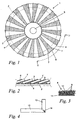
- Figure 1 is a schematic view from above of the sanding element according to the invention.
- Figure 2 is a schematic side-view according to line II-II of the sanding element from figure 1.
- Figure 3 is a schematic cross section to a larger scale of a compressible lamella according to the invention, represented in greater detail.
- Figure 4 schematically represents a view from above of two pipes which are welded together at an angle of 90°.
- the invention generally concerns a sanding element, more particularly a laminated disc, which contains successive overlapping lamellas. These lamellas are alternately formed of sanding lamellas, whose outer surface or free surface is provided with sanding grains, and compressible lamellas upon which the sanding lamellas rest.
- Figure 1 represents such a sanding element in the form of a laminated disc 1.
- the latter contains an almost non-deformable round, disc-shaped support 2 upon which a sanding lamella 3 and a compressible lamella 4 are alternately fixed, in such a manner that each lamella 4 overlaps with a sanding lamella 3.
- the sanding lamella 3 hereby each time rests with its operational part on a corresponding compressible lamella 4.
- Said support 2 has a central opening 5 via which the laminated disc 1 can be mounted on a drive in a manner known as such.
- This drive which is not represented in the figures, makes it possible to rotate the laminated disc 1 at high speed around its axis, whereas the disc 1 is pressed against a workpiece, such that the lamellas 3 and 4 make contact with a surface of said workpiece to be finished.
- the disc according to the invention hereby makes an even contact with the surface of the workpiece with an almost uniform pressure, thanks to the compressibility of the lamellas 4.
- the sanding lamellas 3 are formed for example of a cotton or polyester textile fabric onto which are fixed sanding grains by means of a bonding layer.
- lamellas 3 are formed for example of abrasive cloth.
- these lamellas may also be formed of a paper, a polyester or a mixed support such as polyester cotton onto which are provided sanding grains.
- the compressible lamellas 4 mainly consist of fibres 10. More particularly, these compressible lamellas 4 are formed of non-woven synthetic fibres 10 which are joined together by means of a synthetic resin and thus have a three-dimensional open fibre structure. This fibre structure is glued onto a woven base 11, or anchored thereto in another manner.
- thermosetting synthetic resin is preferably used as said synthetic resin.
- the synthetic fibres 10 are formed for example of polyamide yarns having a diameter between 0.75 and 0.85 mm.
- each sanding lamella 3 is at least partly supported by a compressible lamella 4.
- a practically homogenous pressure will be exerted in the contact surface between said workpiece and the laminated disc 1, as already mentioned above.
- the thickness of the compressible lamellas 4 is preferably at least equal to three times the thickness of said sanding lamellas 3.
- the thickness of the sanding lamellas 3 is almost 0.5 mm to 1 mm, whereas the thickness of the compressible lamellas 4 is for example in the order of magnitude of 3 to 8 mm.
- Every lamella 3 and 4 forms a rectangle with a short side 6 having a length of almost 20 mm and a long side 7 of some 30 mm.
- the long side 7 of the top side of the lamellas 3 and 4, or in other words the free edge thereof, extends practically radially onto the support 2, whereas the short side 6 is situated in a tangent plane on the circumference of the lamellas.
- the lamellas 3 and 4 overlap in the direction of their short side 6, over a distance which is practically equal to 2/3 to 5/6 of the length of this short side 6.
- the lamellas 3 and 4 preferably overlap over a distance of 3/4 of the length of the short side 6.
- the lamellas 3 and 4 are fixed tightly to said support 2 by means of a layer of glue 8.
- the laminated disc 1 according to the invention is particularly interesting when it is used in order to remove a surface layer on metal surfaces.
- Figure 4 schematically represents a workpiece consisting of two pipes 12 and 13 made of stainless steel with a diameter of 40 mm which are welded together at right angles.
- the formed weld 14 extends at an angle of 45° in relation to the axis of the pipes 12 and 13.
- a conventional aggressive sanding instrument such as a fibre disc, a lamella sanding disc, a trimming disc, etc.
- a weld 14 of the workpiece is smoothened by means of what is called a conventional finishing disc, which mainly has a three-dimensional open fibre structure in which are provided sanding grains.
- the finishing disc will be entirely worn after smoothening the surface of five workpieces.
- the same finishing process is carried out by means of the laminated disc 1 according to the invention, it is found that one and the same disc can treat sixteen of such workpieces before the disc has worn out.
- the sanding lamellas and the compressible lamellas may contain all sorts of sanding grains, such as for example ceramic sanding grains or aluminium oxide grains, zirconium oxide grains, silicon carbide or an agglomerate of these grains.
- sanding grains such as for example ceramic sanding grains or aluminium oxide grains, zirconium oxide grains, silicon carbide or an agglomerate of these grains.
- structured sanding grains which are described for example in European patent EP 1 011 924 and which are provided for example according to a regular pattern and with a specific orientation on the lamellas of the sanding element.
- Such structured grains are formed for example of conventional sanding grains whose surface is coated with what are called functional powders, such as very fine sanding grains, antistatic additives, lubricants, etc.
- the sanding lamellas 3 and/or the compressible lamellas 4 may be composed of several lamellas of the same type.
- the sanding element contains a succession of overlapping groups of lamellas, whereby these groups are alternately formed of at least one sanding lamella 3 and at least one compressible lamella 4.
- Each group of sanding lamellas 3 hereby rests on a group of compressible lamellas 4.
- a group of sanding lamellas containing for example two or more sanding lamellas 3 can rest on only one compressible lamella 4 or that for example each sanding lamella 3 can rest on a group of compressible lamellas 4.
- the lamellas of each group of lamellas preferably overlap.
- the lamellas 3 and 4 shoud not necessarily be fixed onto a disc-shaped support, but they could also be fixed for example onto a closed belt.
- the sanding element according to the invention cannot only be applied to finish welded joints made of stainless steel, but it can also be used to improve the surface roughness in general of any material whatsoever, such as for example, iron alloys, ferrous and non-ferrous alloys, stone, plastics, etc.
Claims (15)
- Elément de ponçage comprenant une succession de lamelles chevauchantes (3, 4) contenant des grains de ponçage (9), lesdites lamelles (3, 4) étant alternativement constituées de lamelles de ponçage (3) et de lamelles compressibles (4), caractérisé en ce que la partie opérationnelle de chaque lamelle de ponçage (3) repose sur une lamelle compressible (4) et est supportée par cette lamelle compressible (4).
- Elément de ponçage selon la revendication 1, caractérisé en ce que lesdites lamelles compressibles (4) contiennent des grains de ponçage (9) .
- Elément de ponçage selon la revendication 1 ou 2, caractérisé en ce que lesdites lamelles de ponçage (3) et/ou les lamelles compressibles (4) forment un groupe de plusieurs lamelles du type concerné.
- Elément de ponçage selon l'une quelconque des revendications 1 à 3, caractérisé en ce que lesdites lamelles compressibles (4) sont élastiquement compressibles.
- Elément de ponçage selon l'une quelconque des revendications 1 à 4, caractérisé en ce que lesdites lamelles compressibles (4) présentent une structure ouverte.
- Elément de ponçage selon l'une quelconque des revendications 1 à 5, caractérisé en ce que lesdites lamelles compressibles (4) contiennent des fibres non tissées (10), plus particulièrement des fibres synthétiques non tissées (10) .
- Elément de ponçage selon la revendication 6, caractérisé en ce que des grains de ponçage (9) sont prévus sur lesdites fibres (10).
- Elément de ponçage selon la revendication 6 ou 7, caractérisé en ce que lesdites fibres (10) sont jointes les unes aux autres au moyen d'une résine synthétique et forment ainsi une structure fibreuse ouverte tridimensionnelle.
- Elément de ponçage selon la revendication 8, caractérisé en ce que les grains de ponçage (9) adhèrent auxdites fibres (10) au moyen de la résine synthétique mentionnée ci-dessus.
- Elément de ponçage selon l'une quelconque des revendications 1 à 9, caractérisé en ce que lesdites lamelles de ponçage (3) sont constituées d'une toile abrasive.
- Elément de ponçage selon l'une quelconque des revendications 1 à 10, caractérisé en ce que l'épaisseur desdits lamelles compressibles (4) est au moins égale au triple de l'épaisseur desdites lamelles de ponçage (3).
- Elément de ponçage selon l'une quelconque des revendications 1 à 11, caractérisé en ce que lesdites lamelles (3, 4) sont fixées sur un support rond en forme de disque (2), dans lequel les bords libres (7) de ces lamelles (3, 4) s'étendent presque radialement.
- Elément de ponçage selon la revendication 3, caractérisé en ce que chaque groupe de lamelles de ponçage (3) repose sur un groupe de lamelles compressibles (4), et la partie opérationnelle d'une lamelle de ponçage (3) de chaque groupe de lamelles de ponçage (3) repose sur une lamelle compressible (4).
- Elément de ponçage selon la revendication 13, caractérisé en ce que les lamelles de chaque groupe de lamelles se chevauchent mutuellement.
- Elément de ponçage selon la revendication 13 ou 14, caractérisé en ce que ledit groupe de lamelles de ponçage (3) contient deux lamelles de ponçage (3) et repose sur une seule lamelle compressible (4).
Priority Applications (2)
| Application Number | Priority Date | Filing Date | Title |
|---|---|---|---|
| SI200530077T SI1684945T1 (sl) | 2004-03-03 | 2005-03-03 | Brusilni element |
| PL05708934T PL1684945T3 (pl) | 2004-03-03 | 2005-03-03 | Element ścierny |
Applications Claiming Priority (2)
| Application Number | Priority Date | Filing Date | Title |
|---|---|---|---|
| BE2004/0116A BE1015278B3 (nl) | 2004-03-03 | 2004-03-03 | Schuurelement. |
| PCT/IB2005/050799 WO2005087436A1 (fr) | 2004-03-03 | 2005-03-03 | Element de ponçage |
Publications (2)
| Publication Number | Publication Date |
|---|---|
| EP1684945A1 EP1684945A1 (fr) | 2006-08-02 |
| EP1684945B1 true EP1684945B1 (fr) | 2007-08-01 |
Family
ID=33480077
Family Applications (1)
| Application Number | Title | Priority Date | Filing Date |
|---|---|---|---|
| EP05708934A Active EP1684945B1 (fr) | 2004-03-03 | 2005-03-03 | Element de pon age |
Country Status (19)
| Country | Link |
|---|---|
| US (3) | US7727056B2 (fr) |
| EP (1) | EP1684945B1 (fr) |
| AT (1) | ATE368549T1 (fr) |
| AU (1) | AU2005221411B2 (fr) |
| BE (1) | BE1015278B3 (fr) |
| BR (1) | BRPI0508394B1 (fr) |
| CA (1) | CA2546320C (fr) |
| DE (1) | DE602005001842T2 (fr) |
| DK (1) | DK1684945T3 (fr) |
| EG (1) | EG24846A (fr) |
| ES (1) | ES2290889T3 (fr) |
| HR (1) | HRP20070483T3 (fr) |
| IL (1) | IL177846A (fr) |
| NO (1) | NO328916B1 (fr) |
| PL (1) | PL1684945T3 (fr) |
| PT (1) | PT1684945E (fr) |
| RS (1) | RS50513B (fr) |
| RU (1) | RU2357850C2 (fr) |
| WO (1) | WO2005087436A1 (fr) |
Cited By (4)
| Publication number | Priority date | Publication date | Assignee | Title |
|---|---|---|---|---|
| US7727056B2 (en) | 2004-03-03 | 2010-06-01 | Cibo N.V. | Sanding element |
| DE202020000786U1 (de) | 2020-02-28 | 2021-05-31 | Wendt Poliertechnik Gmbh & Co. Kg | Polierwerkzeug |
| WO2021170298A1 (fr) | 2020-02-28 | 2021-09-02 | Wendt Poliertechnik Gmbh & Co. Kg | Outil de polissage |
| DE102020001283A1 (de) | 2020-02-28 | 2021-09-02 | Wendt Poliertechnik Gmbh & Co. Kg | Polierwerkzeug |
Families Citing this family (10)
| Publication number | Priority date | Publication date | Assignee | Title |
|---|---|---|---|---|
| US7690970B2 (en) * | 2007-01-19 | 2010-04-06 | Epoxy-Tech, Inc. | Abrasive preparation device with an improved abrasion element assembly |
| DE202009016981U1 (de) * | 2009-12-16 | 2011-04-28 | Rhodius Schleifwerkzeuge Gmbh & Co. Kg | Fächerschleifscheibe |
| DE202010008898U1 (de) * | 2010-10-26 | 2010-12-30 | Lukas-Erzett Vereinigte Schleif- Und Fräswerkzeugfabriken Gmbh & Co. Kg | Schleiflamelle zum Anordnen auf einer um eine Drehachse rotierend antreibbaren Schleifscheibe |
| ES2361346A1 (es) * | 2011-02-21 | 2011-06-16 | Salinas E Hijos S.L. | Disco de láminas para pulir vidrio. |
| ITRE20120015A1 (it) * | 2012-03-07 | 2013-09-08 | Manuel Mazzoni | Utensile a lamelle abrasive per la lavorazione di superfici |
| EP2866974B1 (fr) * | 2012-06-27 | 2017-07-26 | 3M Innovative Properties Company | Article abrasif |
| EP2708326B8 (fr) | 2012-09-18 | 2016-03-09 | PPR GmbH | Disque à surfacer à lamelles |
| ITMI20130734A1 (it) * | 2013-05-07 | 2014-11-08 | Ren S R L | Utensile abrasivo |
| JP7083848B2 (ja) * | 2017-02-22 | 2022-06-13 | エーシーエス インダストリーズ、インク. | セグメント化された回転式フロア用剥離パッド |
| CA3054036A1 (fr) * | 2018-12-28 | 2020-06-28 | Virtual Machines Inc. | Procede et systeme de production de substances a polir |
Family Cites Families (20)
| Publication number | Priority date | Publication date | Assignee | Title |
|---|---|---|---|---|
| DE1694594C3 (de) * | 1960-01-11 | 1975-05-28 | Minnesota Mining And Manufacturing Co., Saint Paul, Minn. (V.St.A.) | Reinigungs- und Polierkörper |
| US3529385A (en) * | 1968-11-12 | 1970-09-22 | Norton Co | Abrasive brush |
| US3706167A (en) * | 1970-10-13 | 1972-12-19 | Schaffner Mfg Co Inc | Finishing apparatus |
| US4078340A (en) * | 1973-12-07 | 1978-03-14 | Minnesota Mining And Manufacturing Company | Low density abrasive pad having different abrasive surfaces |
| US4275529A (en) * | 1979-08-28 | 1981-06-30 | Minnesota Mining And Manufacturing Company | High flap density abrasive flap wheel |
| US4715150A (en) * | 1986-04-29 | 1987-12-29 | Seiken Co., Ltd. | Nonwoven fiber abrasive disk |
| US4659609A (en) * | 1986-05-02 | 1987-04-21 | Kimberly-Clark Corporation | Abrasive web and method of making same |
| US5082720A (en) * | 1988-05-06 | 1992-01-21 | Minnesota Mining And Manufacturing Company | Melt-bondable fibers for use in nonwoven web |
| US4872292A (en) * | 1988-06-22 | 1989-10-10 | Aleck Block | Flap wheel |
| US4991362A (en) * | 1988-09-13 | 1991-02-12 | Minnesota Mining And Manufacturing Company | Hand scouring pad |
| US5025596A (en) * | 1988-09-13 | 1991-06-25 | Minnesota Mining And Manufacturing Company | Hand scouring pad |
| US5752876A (en) * | 1995-10-23 | 1998-05-19 | Weiler Brush Company, Inc. | Flap disc abrasive tool |
| US5996167A (en) * | 1995-11-16 | 1999-12-07 | 3M Innovative Properties Company | Surface treating articles and method of making same |
| WO1997042003A1 (fr) * | 1996-05-03 | 1997-11-13 | Minnesota Mining And Manufacturing Company | Procede et appareil de fabrication d'articles abrasifs |
| US5725876A (en) * | 1996-05-17 | 1998-03-10 | Noven Pharmaceuticals Inc., | Compositions and methods for using low-swell clays in nicotine containing dermal compositions |
| DE19853550C1 (de) * | 1998-11-20 | 2000-03-09 | Ver Schmirgel & Maschf | Fächerschleifscheibe |
| EP1093885A1 (fr) * | 1999-10-18 | 2001-04-25 | Botech AG | Outil de meulage |
| JP2002046073A (ja) * | 2000-08-04 | 2002-02-12 | Kanto Seito Kk | 研磨用軟質孔あきディスク及びその製造方法 |
| BE1015278B3 (nl) | 2004-03-03 | 2005-11-08 | Cibo N V | Schuurelement. |
| DE202004004027U1 (de) * | 2004-03-12 | 2005-07-28 | RHODIUS Oualitätsschleifmittel GmbH & Co KG | Fächerschleifscheibe |
-
2004
- 2004-03-03 BE BE2004/0116A patent/BE1015278B3/nl not_active IP Right Cessation
-
2005
- 2005-03-03 AU AU2005221411A patent/AU2005221411B2/en not_active Ceased
- 2005-03-03 CA CA2546320A patent/CA2546320C/fr active Active
- 2005-03-03 PL PL05708934T patent/PL1684945T3/pl unknown
- 2005-03-03 ES ES05708934T patent/ES2290889T3/es active Active
- 2005-03-03 WO PCT/IB2005/050799 patent/WO2005087436A1/fr active Application Filing
- 2005-03-03 PT PT05708934T patent/PT1684945E/pt unknown
- 2005-03-03 DK DK05708934T patent/DK1684945T3/da active
- 2005-03-03 RS RSP-2007/0418A patent/RS50513B/sr unknown
- 2005-03-03 RU RU2006134726/02A patent/RU2357850C2/ru active
- 2005-03-03 DE DE602005001842T patent/DE602005001842T2/de active Active
- 2005-03-03 BR BRPI0508394-0A patent/BRPI0508394B1/pt active IP Right Grant
- 2005-03-03 US US10/578,256 patent/US7727056B2/en active Active - Reinstated
- 2005-03-03 EP EP05708934A patent/EP1684945B1/fr active Active
- 2005-03-03 AT AT05708934T patent/ATE368549T1/de active
-
2006
- 2006-08-30 EG EGNA2006000807 patent/EG24846A/xx active
- 2006-08-31 IL IL177846A patent/IL177846A/en active IP Right Grant
- 2006-09-29 NO NO20064419A patent/NO328916B1/no not_active IP Right Cessation
-
2007
- 2007-10-17 HR HR20070483T patent/HRP20070483T3/xx unknown
-
2010
- 2010-03-29 US US12/749,506 patent/US7922564B2/en active Active
- 2010-08-23 US US12/861,827 patent/US7828633B1/en active Active - Reinstated
Cited By (6)
| Publication number | Priority date | Publication date | Assignee | Title |
|---|---|---|---|---|
| US7727056B2 (en) | 2004-03-03 | 2010-06-01 | Cibo N.V. | Sanding element |
| US7828633B1 (en) | 2004-03-03 | 2010-11-09 | Cibo N.V. | Sanding element |
| US7922564B2 (en) | 2004-03-03 | 2011-04-12 | Cibo N.V. | Sanding element |
| DE202020000786U1 (de) | 2020-02-28 | 2021-05-31 | Wendt Poliertechnik Gmbh & Co. Kg | Polierwerkzeug |
| WO2021170298A1 (fr) | 2020-02-28 | 2021-09-02 | Wendt Poliertechnik Gmbh & Co. Kg | Outil de polissage |
| DE102020001283A1 (de) | 2020-02-28 | 2021-09-02 | Wendt Poliertechnik Gmbh & Co. Kg | Polierwerkzeug |
Also Published As
| Publication number | Publication date |
|---|---|
| PT1684945E (pt) | 2007-11-09 |
| BE1015278B3 (nl) | 2005-11-08 |
| HRP20070483T3 (en) | 2007-12-31 |
| DE602005001842T2 (de) | 2008-05-29 |
| ATE368549T1 (de) | 2007-08-15 |
| IL177846A0 (en) | 2006-12-31 |
| BRPI0508394A (pt) | 2007-08-07 |
| NO20064419L (no) | 2006-09-29 |
| EP1684945A1 (fr) | 2006-08-02 |
| BRPI0508394B1 (pt) | 2018-06-12 |
| CA2546320A1 (fr) | 2005-09-22 |
| IL177846A (en) | 2010-05-31 |
| AU2005221411B2 (en) | 2010-08-12 |
| ES2290889T3 (es) | 2008-02-16 |
| PL1684945T3 (pl) | 2007-12-31 |
| EG24846A (en) | 2010-10-24 |
| RU2357850C2 (ru) | 2009-06-10 |
| DK1684945T3 (da) | 2007-10-29 |
| US7828633B1 (en) | 2010-11-09 |
| RU2006134726A (ru) | 2008-04-10 |
| US20090088054A1 (en) | 2009-04-02 |
| US7727056B2 (en) | 2010-06-01 |
| NO328916B1 (no) | 2010-06-14 |
| AU2005221411A1 (en) | 2005-09-22 |
| BE1015278A0 (nl) | 2004-12-07 |
| US20100184358A1 (en) | 2010-07-22 |
| RS50513B (sr) | 2010-03-02 |
| WO2005087436A1 (fr) | 2005-09-22 |
| US7922564B2 (en) | 2011-04-12 |
| DE602005001842D1 (de) | 2007-09-13 |
| CA2546320C (fr) | 2012-11-20 |
Similar Documents
| Publication | Publication Date | Title |
|---|---|---|
| EP1684945B1 (fr) | Element de pon age | |
| US7108587B2 (en) | Backup shoe for microfinishing and methods | |
| US6234886B1 (en) | Multiple abrasive assembly and method | |
| US5454751A (en) | Marble, granite and stone finishing and abrasive pads therefor | |
| KR100210409B1 (ko) | 기재에 패턴화된 표면을 제공하는 방법 | |
| US6261164B1 (en) | Multiple abrasive assembly and method | |
| US5910041A (en) | Lapping apparatus and process with raised edge on platen | |
| US5993298A (en) | Lapping apparatus and process with controlled liquid flow across the lapping surface | |
| US6120352A (en) | Lapping apparatus and lapping method using abrasive sheets | |
| CA1128320A (fr) | Outil de meulage pour l'usinage par enlevement de metal | |
| US20130324021A1 (en) | Diamond impregnated polishing pad with diamond pucks | |
| US6066034A (en) | V-shaped flap disc abrasive tool | |
| US6506100B2 (en) | Grinding tool, processing machine with a grinding tool, use of a grinding tool and method for processing a work piece | |
| US5871399A (en) | Flap wheel | |
| US6589106B1 (en) | Consumable polishing element, particularly for finishing optical glass | |
| JP7274499B2 (ja) | 含浸織布及び研磨粒子を含む研磨製品 | |
| US20230136260A1 (en) | Polishing tool | |
| US20220080555A1 (en) | Bilateral abrasive disc pad | |
| EP1203635A1 (fr) | Article en bois présentant une surface particulièrement lisse et procédé de réalisation | |
| JPH0511963Y2 (fr) |
Legal Events
| Date | Code | Title | Description |
|---|---|---|---|
| PUAI | Public reference made under article 153(3) epc to a published international application that has entered the european phase |
Free format text: ORIGINAL CODE: 0009012 |
|
| 17P | Request for examination filed |
Effective date: 20060428 |
|
| AK | Designated contracting states |
Kind code of ref document: A1 Designated state(s): AT BE BG CH CY CZ DE DK EE ES FI FR GB GR HU IE IS IT LI LT LU MC NL PL PT RO SE SI SK TR |
|
| AX | Request for extension of the european patent |
Extension state: AL BA HR LV MK YU |
|
| GRAP | Despatch of communication of intention to grant a patent |
Free format text: ORIGINAL CODE: EPIDOSNIGR1 |
|
| GRAS | Grant fee paid |
Free format text: ORIGINAL CODE: EPIDOSNIGR3 |
|
| GRAA | (expected) grant |
Free format text: ORIGINAL CODE: 0009210 |
|
| AK | Designated contracting states |
Kind code of ref document: B1 Designated state(s): AT BE BG CH CY CZ DE DK EE ES FI FR GB GR HU IE IS IT LI LT LU MC NL PL PT RO SE SI SK TR |
|
| AX | Request for extension of the european patent |
Extension state: AL BA HR LV MK YU |
|
| REG | Reference to a national code |
Ref country code: GB Ref legal event code: FG4D |
|
| REG | Reference to a national code |
Ref country code: CH Ref legal event code: EP |
|
| REG | Reference to a national code |
Ref country code: IE Ref legal event code: FG4D |
|
| REF | Corresponds to: |
Ref document number: 602005001842 Country of ref document: DE Date of ref document: 20070913 Kind code of ref document: P |
|
| REG | Reference to a national code |
Ref country code: RO Ref legal event code: EPE |
|
| REG | Reference to a national code |
Ref country code: HR Ref legal event code: TUEP Ref document number: P20070483 Country of ref document: HR |
|
| REG | Reference to a national code |
Ref country code: DK Ref legal event code: T3 |
|
| REG | Reference to a national code |
Ref country code: CH Ref legal event code: NV Representative=s name: ISLER & PEDRAZZINI AG |
|
| REG | Reference to a national code |
Ref country code: SE Ref legal event code: TRGR |
|
| REG | Reference to a national code |
Ref country code: PT Ref legal event code: SC4A Free format text: AVAILABILITY OF NATIONAL TRANSLATION Effective date: 20071026 |
|
| REG | Reference to a national code |
Ref country code: GR Ref legal event code: EP Ref document number: 20070403162 Country of ref document: GR |
|
| REG | Reference to a national code |
Ref country code: EE Ref legal event code: FG4A Ref document number: E001481 Country of ref document: EE Effective date: 20071101 |
|
| ET | Fr: translation filed | ||
| REG | Reference to a national code |
Ref country code: HR Ref legal event code: T1PR Ref document number: P20070483 Country of ref document: HR Ref country code: PL Ref legal event code: T3 |
|
| PG25 | Lapsed in a contracting state [announced via postgrant information from national office to epo] |
Ref country code: BG Free format text: LAPSE BECAUSE OF FAILURE TO SUBMIT A TRANSLATION OF THE DESCRIPTION OR TO PAY THE FEE WITHIN THE PRESCRIBED TIME-LIMIT Effective date: 20071101 Ref country code: IS Free format text: LAPSE BECAUSE OF FAILURE TO SUBMIT A TRANSLATION OF THE DESCRIPTION OR TO PAY THE FEE WITHIN THE PRESCRIBED TIME-LIMIT Effective date: 20071201 |
|
| REG | Reference to a national code |
Ref country code: ES Ref legal event code: FG2A Ref document number: 2290889 Country of ref document: ES Kind code of ref document: T3 |
|
| REG | Reference to a national code |
Ref country code: HU Ref legal event code: AG4A Ref document number: E002348 Country of ref document: HU |
|
| PG25 | Lapsed in a contracting state [announced via postgrant information from national office to epo] |
Ref country code: SK Free format text: LAPSE BECAUSE OF FAILURE TO SUBMIT A TRANSLATION OF THE DESCRIPTION OR TO PAY THE FEE WITHIN THE PRESCRIBED TIME-LIMIT Effective date: 20070801 |
|
| PLBE | No opposition filed within time limit |
Free format text: ORIGINAL CODE: 0009261 |
|
| STAA | Information on the status of an ep patent application or granted ep patent |
Free format text: STATUS: NO OPPOSITION FILED WITHIN TIME LIMIT |
|
| 26N | No opposition filed |
Effective date: 20080506 |
|
| PG25 | Lapsed in a contracting state [announced via postgrant information from national office to epo] |
Ref country code: MC Free format text: LAPSE BECAUSE OF NON-PAYMENT OF DUE FEES Effective date: 20080331 |
|
| REG | Reference to a national code |
Ref country code: EE Ref legal event code: HC1A Ref document number: E001481 Country of ref document: EE |
|
| PG25 | Lapsed in a contracting state [announced via postgrant information from national office to epo] |
Ref country code: CY Free format text: LAPSE BECAUSE OF FAILURE TO SUBMIT A TRANSLATION OF THE DESCRIPTION OR TO PAY THE FEE WITHIN THE PRESCRIBED TIME-LIMIT Effective date: 20070801 |
|
| PG25 | Lapsed in a contracting state [announced via postgrant information from national office to epo] |
Ref country code: LU Free format text: LAPSE BECAUSE OF NON-PAYMENT OF DUE FEES Effective date: 20080303 |
|
| REG | Reference to a national code |
Ref country code: FR Ref legal event code: PLFP Year of fee payment: 12 |
|
| REG | Reference to a national code |
Ref country code: FR Ref legal event code: PLFP Year of fee payment: 13 |
|
| REG | Reference to a national code |
Ref country code: FR Ref legal event code: PLFP Year of fee payment: 14 |
|
| REG | Reference to a national code |
Ref country code: HR Ref legal event code: ODRP Ref document number: P20070483 Country of ref document: HR Payment date: 20190304 Year of fee payment: 15 |
|
| PGFP | Annual fee paid to national office [announced via postgrant information from national office to epo] |
Ref country code: FI Payment date: 20190327 Year of fee payment: 15 Ref country code: RO Payment date: 20190308 Year of fee payment: 15 |
|
| PGFP | Annual fee paid to national office [announced via postgrant information from national office to epo] |
Ref country code: EE Payment date: 20190305 Year of fee payment: 15 Ref country code: HU Payment date: 20190312 Year of fee payment: 15 |
|
| REG | Reference to a national code |
Ref country code: HR Ref legal event code: PBON Ref document number: P20070483 Country of ref document: HR Effective date: 20200303 |
|
| REG | Reference to a national code |
Ref country code: FI Ref legal event code: MAE |
|
| REG | Reference to a national code |
Ref country code: EE Ref legal event code: MM4A Ref document number: E001481 Country of ref document: EE Effective date: 20200331 |
|
| PG25 | Lapsed in a contracting state [announced via postgrant information from national office to epo] |
Ref country code: FI Free format text: LAPSE BECAUSE OF NON-PAYMENT OF DUE FEES Effective date: 20200303 Ref country code: RO Free format text: LAPSE BECAUSE OF NON-PAYMENT OF DUE FEES Effective date: 20200303 |
|
| REG | Reference to a national code |
Ref country code: LT Ref legal event code: MM4D Effective date: 20201127 |
|
| PG25 | Lapsed in a contracting state [announced via postgrant information from national office to epo] |
Ref country code: SE Free format text: LAPSE BECAUSE OF NON-PAYMENT OF DUE FEES Effective date: 20200304 Ref country code: HU Free format text: LAPSE BECAUSE OF NON-PAYMENT OF DUE FEES Effective date: 20200304 Ref country code: LT Free format text: LAPSE BECAUSE OF NON-PAYMENT OF DUE FEES Effective date: 20201127 Ref country code: EE Free format text: LAPSE BECAUSE OF NON-PAYMENT OF DUE FEES Effective date: 20200331 |
|
| PGFP | Annual fee paid to national office [announced via postgrant information from national office to epo] |
Ref country code: IE Payment date: 20230327 Year of fee payment: 19 Ref country code: FR Payment date: 20230328 Year of fee payment: 19 Ref country code: DK Payment date: 20230329 Year of fee payment: 19 Ref country code: CZ Payment date: 20230223 Year of fee payment: 19 Ref country code: AT Payment date: 20230221 Year of fee payment: 19 |
|
| PGFP | Annual fee paid to national office [announced via postgrant information from national office to epo] |
Ref country code: TR Payment date: 20230222 Year of fee payment: 19 Ref country code: SI Payment date: 20230221 Year of fee payment: 19 Ref country code: PT Payment date: 20230220 Year of fee payment: 19 Ref country code: PL Payment date: 20230221 Year of fee payment: 19 Ref country code: IT Payment date: 20230321 Year of fee payment: 19 Ref country code: GR Payment date: 20230331 Year of fee payment: 19 Ref country code: GB Payment date: 20230327 Year of fee payment: 19 Ref country code: DE Payment date: 20230329 Year of fee payment: 19 Ref country code: BE Payment date: 20230328 Year of fee payment: 19 |
|
| PGFP | Annual fee paid to national office [announced via postgrant information from national office to epo] |
Ref country code: NL Payment date: 20230326 Year of fee payment: 19 |
|
| PGFP | Annual fee paid to national office [announced via postgrant information from national office to epo] |
Ref country code: ES Payment date: 20230403 Year of fee payment: 19 Ref country code: CH Payment date: 20230402 Year of fee payment: 19 |
|
| PGFP | Annual fee paid to national office [announced via postgrant information from national office to epo] |
Ref country code: GR Payment date: 20240326 Year of fee payment: 20 |
|
| PGFP | Annual fee paid to national office [announced via postgrant information from national office to epo] |
Ref country code: NL Payment date: 20240326 Year of fee payment: 20 Ref country code: IE Payment date: 20240327 Year of fee payment: 20 |