EP1684133A2 - Uhrwerk - Google Patents
Uhrwerk Download PDFInfo
- Publication number
- EP1684133A2 EP1684133A2 EP05028472A EP05028472A EP1684133A2 EP 1684133 A2 EP1684133 A2 EP 1684133A2 EP 05028472 A EP05028472 A EP 05028472A EP 05028472 A EP05028472 A EP 05028472A EP 1684133 A2 EP1684133 A2 EP 1684133A2
- Authority
- EP
- European Patent Office
- Prior art keywords
- rotation
- toothing
- rotary member
- movement according
- control
- Prior art date
- Legal status (The legal status is an assumption and is not a legal conclusion. Google has not performed a legal analysis and makes no representation as to the accuracy of the status listed.)
- Withdrawn
Links
Images


Classifications
-
- G—PHYSICS
- G04—HOROLOGY
- G04B—MECHANICALLY-DRIVEN CLOCKS OR WATCHES; MECHANICAL PARTS OF CLOCKS OR WATCHES IN GENERAL; TIME PIECES USING THE POSITION OF THE SUN, MOON OR STARS
- G04B3/00—Normal winding of clockworks by hand or mechanically; Winding up several mainsprings or driving weights simultaneously
- G04B3/04—Rigidly-mounted keys, knobs or crowns
-
- G—PHYSICS
- G04—HOROLOGY
- G04B—MECHANICALLY-DRIVEN CLOCKS OR WATCHES; MECHANICAL PARTS OF CLOCKS OR WATCHES IN GENERAL; TIME PIECES USING THE POSITION OF THE SUN, MOON OR STARS
- G04B27/00—Mechanical devices for setting the time indicating means
- G04B27/002—The setting apparatus being crown shaped
Definitions
- the present invention relates to a watch movement comprising a rotary member for an external manual control connected by at least one connecting member to at least one element of the movement and capable of being rotated in two opposite directions.
- Rotating members of the aforementioned type are well known and are most often in the form of a crown that the user can rotate in two opposite directions to control one or two features, such as setting the time or date. winding a barrel.
- the present invention aims to improve the known crowns and allow to drive safely and independently at least two functions with the ring in the same axial position pulled or not pulled.
- the movement according to the invention is characterized for this purpose by the fact that it comprises at least one selection device associated with the rotary member and arranged to occupy at least two different positions comprising a first position in which it authorizes the rotation of the connecting member in a first direction and makes it impossible to rotate the connecting member in a second direction, and a second position in which it makes impossible the rotation of the connecting member in the first direction and allows the rotation of the connecting member in the second direction.
- the direction of rotation of the crown is secure because the selection device only allows the direction of rotation of the crown chosen by the user by its prior action on the selection device.
- the selection device comprises a locking device arranged to lock in said first position the rotation of the rotary member and the connecting member in said second direction and so as to lock in said second position rotates the rotary member and the connecting member in said first direction.
- the selection device is arranged to occupy an additional position in which it makes impossible the rotation of the connecting member in both directions of rotation.
- the locking device comprises at least two locking members capable of cooperating with at least one toothing integral with the rotary member and at least one control member arranged so as to establish or interrupt the contact of said toothing with the one or other of the locking members.
- the two locking members are constituted by a first and second spring blades arranged to cooperate by their free end with the toothing so as to oppose for the first spring blade to a rotation of the organ rotating in the second direction and to allow a rotation of this rotary member in the first direction, and so as to oppose for the second leaf rotates the rotary member in the first direction and to allow a rotation of this rotating member in the second direction, said control member being provided with at least one piece arranged to move one or the other spring blades of the toothing according to the position of the control member selected by a user .
- control member is constituted by a rocker rotatably mounted around a ring constituting said rotary member, said rocker being provided with a protuberance in the form of a semi-cylindrical sector intended to cooperate with one or the other blades spring to separate them from the toothing according to the position of the latch chosen by the user.
- the two locking members are constituted by blockers mounted sliding in cylinders each biased by a spring towards a rest position, and each comprising at least one projection capable of cooperating with a toothing integral with the rotary member.
- these blockers being mounted on at least one movable control part movable to put one and / or the other of the blockers in contact with said toothing to lock the rotary member in one or the other both directions of rotation.
- This variant allows a very high build strength and reliable operation.
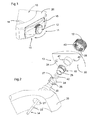
- the first embodiment comprises a movement 10 with a rotary member 11, such as a ring 12, intended to serve as an external manual control connected by at least one connecting member 14 to at least an element of the movement and capable of being rotated in two opposite directions.
- This crown can thus serve as a winding and / or organ for controlling functions such as time setting, time zones, the date, the moon phase, a repetition or a ring, etc.
- the rotary member 11 is provided with a selection device 13 for actuating particular functions of the movement and comprising at least one locking device 15 arranged to occupy at least two different positions comprising a first position in which it blocks the rotation of the ring 12 in a first counterclockwise direction and allows the rotation of the rotary member in a second clockwise direction, and a second position in which it blocks the rotation of the crown in the second clockwise direction and allows its rotation in the first anticlockwise direction.
- a middle part 20 of the movement housing comprises a bore 21 into which a tube to be chased 22 is driven and glued.
- the latter is traversed by a rod 23 serving as connecting member 14 secured to the ring 12 by driving-gluing or screwing.
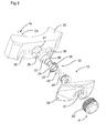
- the locking device 15 comprises a spring ring 24 mounted on a support tube 25 which is screwed onto the tube to be driven 22.
- the spring ring 24 has two leaf springs 26, 27 protruding on its periphery to cooperate with an internal toothing 28 of the crown 12.
- the locking device 15 is further provided with a control lever 30 rotatably mounted around the ring 12 on the tube to be driven 22 and the support tube 25.
- This rocker 30 has a protuberance 31 in the form of a semi-circular sector. cylindrical disposed between the spring ring 24 and the internal toothing 28 of the ring 12.
- This control lever 30 comprises a stop 34 intended to cooperate with two recesses 35, 36 provided in the middle part 20 to limit the rotation of the latch 30 to 180 °.
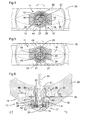
- the protrusion 31 is interposed between the leaf spring 26 and the internal toothing 28 to move the leaf spring 26 of the toothing, which allows a rotation of the ring 12 in a clockwise direction.
- the leaf spring 27, which is oriented in a substantially tangential direction of the spring ring 24 enters at its end between the teeth of the toothing 28 to oppose a rotation of the ring 12 in a counterclockwise direction to the figure 4.
- Two ball pawls 38, 39 are mounted in the middle part 20 (FIG. 6) and cooperate with two recesses 40, 41 provided on the control lever 30 to hold the latter in this position.
- control lever When it is desired to control another function, the control lever is rotated 180 ° in a clockwise direction (FIG 4, 5) to occupy a second position illustrated in FIG.
- the control lever 30 is again held in position by the two ball pawls 38, 39.
- the protuberance 31 does not separate the spring blade 26 or the spring blade 27 from the toothing so that the ring 12 is locked in both sense of rotation.
- the protrusion 31 could occupy a larger sector, for example 210 °, so that it allows to separate the two spring blades 26 and 27 of the toothing 28 in said intermediate position to allow rotations clockwise and counterclockwise.
- the locking device 15 is provided with a seal 42 disposed between a central portion 43 of the ring 12 and the support tube 25.
- Markings 44 (FIG 4, 5) on the flip-flop 30 or the middle 20 could make it possible to visualize the direction in which the crown can be rotated by the user and / or the function that it will be possible to control.
- the blocking device 15 allows in particular a dual control function with the ring in the same drawn position, for example to control either a time zone function when the ring is turned in one direction, an update function when the crown is turned in the other direction.
- the selection and locking devices are independent of the movement and its features. They may also be adapted to select more than two possible functions by pulling the ring axially on two or more predetermined longitudinal positions.
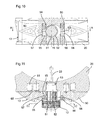
- the selection device 13 also comprises a locking device 15, but instead of presenting a rotary control lever, the locking device comprises a sliding control part 50 mounted on the middle part of the movement.
- the ring 12 is extended by a cylindrical portion 51 having a toothing 52 and connected to a connecting rod 23.
- a seal 53 seals the crown.
- the control part 50 is provided with two blockers 55, 56 slidably mounted in cylinders 57, 58 on both sides of the cylindrical part 51.
- the rib 63 of the right blocker 56 is engaged with the toothing 52 to block a clockwise rotation, but allow a counterclockwise rotation against the effect of the spring 60.
- the selection device 13 further comprises four ball pawls 61 mounted in the caseband 20 and capable of cooperating with four recesses 65 provided in the control part 50 so as to maintain this control part in the median position (FIG. one or the other of the locking positions (Fig. 11).
- the selection device 13 has a locking device 15 comprising two control flip-flops 70, 71 pivotally articulated to the middle part 20 by means of a screw 73 acting as an axis. pivoting.
- Each flip-flop is provided with a slider 74 cooperating with a slider 75 (FIG 15) in which it is introduced.
- Two ball pawls 76 are mounted in the middle part 20 and cooperate with recesses 77 provided on the latches to maintain the latter in a rest position.
- Each latch 70, 71 further comprises a blocker 78, 79 slidably mounted in a cylinder 80, 81 provided in the rockers on both sides of the ring 12 which is provided with an external toothing 82.
- the two blockers are solicited by springs 83 to 84 to a rest position and each comprise an annular rib 86 capable of cooperating with the outer toothing 82 of the crown.
- the ring 12 can be rotated in a clockwise or counterclockwise direction. If one of the latches 70,71 is pivoted, the other latch is brought to its rest position. For example if you turn the latch 70 in Figure 14, the flip-flop 71 is returned to the rest position with its blocker 79 engaged with the ring 12.
- the fourth embodiment is illustrated in Figures 16 to 18. It has a selection device 13 integrated in the ring 12.
- the latter comprises an inner ring 90 integral with a connecting member 14 connected to at least one element of the movement .
- This inner ring 90 is rotatably mounted in a tube 91 driven into a bore of the middle part.
- the crown further comprises an outer ring 92 that can be actuated manually by a user.
- This outer ring is connected to the inner part by the selection device 13, comprising a coupling mechanism 104.
- the latter has a latch 93 pivotally mounted about an axis 94 and having a right toothing 95 and a left toothing 96 for to selectively cooperate with an internal toothing 97 of the outer ring 92 (Fig 18).
- a control part 98 is pivotally mounted on the inner ring 90 and carries an actuating finger 99 biased by a spring 100 against the latch 93.
- the crown could occupy several axial positions and thus drive twice as many features.
- the scales and other control parts may have another shape.
- the movement could have several rotating control members, each equipped with a selection device.
Applications Claiming Priority (1)
| Application Number | Priority Date | Filing Date | Title |
|---|---|---|---|
| CH00078/05A CH695470A5 (fr) | 2005-01-19 | 2005-01-19 | Dispositif de commande manuelle pour un mouvement d'horlogerie. |
Publications (2)
| Publication Number | Publication Date |
|---|---|
| EP1684133A2 true EP1684133A2 (de) | 2006-07-26 |
| EP1684133A3 EP1684133A3 (de) | 2010-05-26 |
Family
ID=36293936
Family Applications (1)
| Application Number | Title | Priority Date | Filing Date |
|---|---|---|---|
| EP05028472A Withdrawn EP1684133A3 (de) | 2005-01-19 | 2005-12-24 | Uhrwerk |
Country Status (5)
| Country | Link |
|---|---|
| US (1) | US7404669B2 (de) |
| EP (1) | EP1684133A3 (de) |
| JP (1) | JP2006201168A (de) |
| CN (1) | CN1808310A (de) |
| CH (1) | CH695470A5 (de) |
Cited By (1)
| Publication number | Priority date | Publication date | Assignee | Title |
|---|---|---|---|---|
| CN112433459A (zh) * | 2020-11-26 | 2021-03-02 | 歌尔科技有限公司 | 一种表冠及具有该表冠的腕戴设备 |
Families Citing this family (13)
| Publication number | Priority date | Publication date | Assignee | Title |
|---|---|---|---|---|
| JP5285546B2 (ja) * | 2009-08-28 | 2013-09-11 | セイコーインスツル株式会社 | 手巻き式携帯時計及びこの時計が備える竜頭の操作方法 |
| US8783944B2 (en) * | 2011-07-22 | 2014-07-22 | Casio Computer Co., Ltd. | Switch device and wristwatch |
| EP2746873B1 (de) * | 2012-12-21 | 2017-11-15 | Meco S.A. | Modularer Zusammenbau eines Druckknopfs |
| ITFI20130090A1 (it) * | 2013-04-23 | 2014-10-24 | Hi Tek Office S R L | Dispositivo estrai-corona per orologi. |
| CH708356A1 (fr) * | 2013-07-17 | 2015-01-30 | Société Anonyme De La Manufacture D Horlogerie Audemars Piguet & Cie | Dispositif de commande pour pièce d'horlogerie. |
| AU201811022S (en) * | 2017-10-17 | 2018-03-15 | Omega Sa Omega Ag Omega Ltd | Watch |
| EP3495896A1 (de) * | 2017-12-11 | 2019-06-12 | Barigna SA | Armbanduhr, die mit einem steuerorgan des innenmechanismus ausgestattet ist |
| EP3605243A1 (de) * | 2018-07-31 | 2020-02-05 | Montres Breguet S.A. | Uhr-anzeigemechanismus mit variabler geometrie und elastischem zeiger |
| EP3805869A1 (de) * | 2019-10-09 | 2021-04-14 | Meco S.A. | Geschraubte krone |
| JP7457627B2 (ja) | 2019-11-08 | 2024-03-28 | シチズン時計株式会社 | ムーブメント及びこのムーブメントを備えた時計 |
| EP3825778B1 (de) * | 2019-11-21 | 2023-07-12 | The Swatch Group Research and Development Ltd | Steuerkranz für uhr |
| EP4198638A1 (de) | 2021-12-16 | 2023-06-21 | ETA SA Manufacture Horlogère Suisse | Multifunktionelle korrekturvorrichtung für eine uhr und werkzeug zum betätigen einer solchen vorrichtung |
| CN218446386U (zh) * | 2022-10-28 | 2023-02-03 | 乳圆数字科技(深圳)有限公司 | 一种金属轮转动装置 |
Citations (3)
| Publication number | Priority date | Publication date | Assignee | Title |
|---|---|---|---|---|
| US5319617A (en) * | 1991-06-07 | 1994-06-07 | Casio Computer Co., Ltd. | Apparatus case with a rotatable member |
| EP1045298A2 (de) * | 1999-04-15 | 2000-10-18 | Svend Andersen | Aufzugkrone im Uhrengehäuseboden |
| WO2004053599A2 (de) * | 2002-12-06 | 2004-06-24 | Powermike.Com L.P. | Weltzeituhr |
Family Cites Families (8)
| Publication number | Priority date | Publication date | Assignee | Title |
|---|---|---|---|---|
| US3618312A (en) * | 1969-04-29 | 1971-11-09 | Timex Corp | Watch crown |
| US4536095A (en) * | 1984-09-13 | 1985-08-20 | Timex Corporation | Crown setting switch for a wristwatch |
| JP2814068B2 (ja) * | 1994-10-25 | 1998-10-22 | セイコークロック株式会社 | 秒針停止装置付き時計機械体 |
| US6146010A (en) * | 1999-03-08 | 2000-11-14 | Timex Corporation | Combined crown and pusher electro mechanism |
| WO2002044818A1 (fr) * | 2000-12-01 | 2002-06-06 | Tag-Heuer Sa | Boîte de montre |
| US7066301B2 (en) * | 2002-03-20 | 2006-06-27 | Invensys Building Systems, Inc. | Linear actuator having manual override and locking mechanism |
| EP1353245B1 (de) * | 2002-04-09 | 2008-07-16 | Girard-Perregaux S.A. | Betätigungsmechanismus für eine Uhr |
| JP4393837B2 (ja) * | 2003-10-23 | 2010-01-06 | セイコーインスツル株式会社 | 携帯時計 |
-
2005
- 2005-01-19 CH CH00078/05A patent/CH695470A5/fr not_active IP Right Cessation
- 2005-12-24 EP EP05028472A patent/EP1684133A3/de not_active Withdrawn
-
2006
- 2006-01-12 US US11/330,144 patent/US7404669B2/en not_active Expired - Fee Related
- 2006-01-17 JP JP2006008873A patent/JP2006201168A/ja active Pending
- 2006-01-18 CN CN200610006305.9A patent/CN1808310A/zh active Pending
Patent Citations (3)
| Publication number | Priority date | Publication date | Assignee | Title |
|---|---|---|---|---|
| US5319617A (en) * | 1991-06-07 | 1994-06-07 | Casio Computer Co., Ltd. | Apparatus case with a rotatable member |
| EP1045298A2 (de) * | 1999-04-15 | 2000-10-18 | Svend Andersen | Aufzugkrone im Uhrengehäuseboden |
| WO2004053599A2 (de) * | 2002-12-06 | 2004-06-24 | Powermike.Com L.P. | Weltzeituhr |
Cited By (1)
| Publication number | Priority date | Publication date | Assignee | Title |
|---|---|---|---|---|
| CN112433459A (zh) * | 2020-11-26 | 2021-03-02 | 歌尔科技有限公司 | 一种表冠及具有该表冠的腕戴设备 |
Also Published As
| Publication number | Publication date |
|---|---|
| EP1684133A3 (de) | 2010-05-26 |
| CN1808310A (zh) | 2006-07-26 |
| US20060184159A1 (en) | 2006-08-17 |
| CH695470A5 (fr) | 2006-05-31 |
| US7404669B2 (en) | 2008-07-29 |
| JP2006201168A (ja) | 2006-08-03 |
Similar Documents
| Publication | Publication Date | Title |
|---|---|---|
| EP1684133A2 (de) | Uhrwerk | |
| EP1933212B1 (de) | Uhr mit einem Schlagwerk, die einen Sperrhebel umfasst | |
| EP1748330B1 (de) | Vorrichtung mit Spindel zum Aufziehen und zur Zeiteinstellung von Uhren | |
| EP3407144B1 (de) | Uhr, die eine verriegelungsvorrichtung für eine drucktaste umfasst | |
| EP2365407B1 (de) | Vorrichtung zum Aufziehen und zur Zeiteinstellung für ein Uhrwerk | |
| EP1676177A1 (de) | Armbanduhr-drückstück-aufzieh-knopf-steuereinrichtung | |
| EP1933211A1 (de) | Uhr mit Schlagwerk, die einen Sperrhebel mit doppelter Funktion umfasst | |
| EP2984526A2 (de) | Vorrichtung zur auswahl und betätigung der funktionen eines uhrwerks | |
| CH709654B1 (fr) | Bascule d'horlogerie et mécanisme de correction rapide comportant une telle bacule. | |
| FR2781437A1 (fr) | Articulation destinee notamment a un siege de vehicule automobile | |
| CH704250B1 (fr) | Mécanisme de transmission de mouvements axiaux et rotatifs entre deux axes décalés et pièce d'horlogerie comportant un tel mécanisme. | |
| EP1978419A1 (de) | Unidirektionale Kupplung und Korrekturvorrichtung, die eine solche Kupplung umfasst | |
| CH706232B1 (fr) | Pièce d'horlogerie comportant un dispositif de commande et de réglage comportant une couronne et un poussoir coaxial. | |
| WO2001088633A1 (fr) | Dispositif de commande a poussoir pour montre | |
| CH706888B1 (fr) | Ensemble de couronne de montre à verrouillage central. | |
| EP2765463B1 (de) | Mechanismus zur Übertragung von Achsen- und Drehbewegungen zwischen zwei verschobenen Achsen, und Uhr, die mit einem solchen Mechanismus ausgestattet ist | |
| CH714602B1 (fr) | Mécanisme d'une montre pourvue d'une tige de remontoir. | |
| EP1676176A1 (de) | Steuerungseinrichtung mit ausklinkbarer krone für eine armbanduhr | |
| EP3584644A1 (de) | Aufzieh- und korrekturmechanismus mit wippe für uhrwerk | |
| CH706893B1 (fr) | Ensemble de couronne télescopique à effet d'effacement dans le boîtier d'une montre. | |
| FR2525724A1 (fr) | Mecanisme d'activation d'une vanne | |
| CH698141B1 (fr) | Mouvement d'horlogerie mécanique. | |
| CH711524A2 (fr) | Mouvement horloger comprenant un mécanisme de correction de la date. | |
| EP4148503A1 (de) | Vorrichtung zur manuellen steuerung eines mechanismus für eine uhr | |
| CH702802B1 (fr) | Dispositif de commande de remontage et de mise à l'heure pour un mouvement d'horlogerie. |
Legal Events
| Date | Code | Title | Description |
|---|---|---|---|
| PUAI | Public reference made under article 153(3) epc to a published international application that has entered the european phase |
Free format text: ORIGINAL CODE: 0009012 |
|
| AK | Designated contracting states |
Kind code of ref document: A2 Designated state(s): AT BE BG CH CY CZ DE DK EE ES FI FR GB GR HU IE IS IT LI LT LU LV MC NL PL PT RO SE SI SK TR |
|
| AX | Request for extension of the european patent |
Extension state: AL BA HR MK YU |
|
| PUAL | Search report despatched |
Free format text: ORIGINAL CODE: 0009013 |
|
| AK | Designated contracting states |
Kind code of ref document: A3 Designated state(s): AT BE BG CH CY CZ DE DK EE ES FI FR GB GR HU IE IS IT LI LT LU LV MC NL PL PT RO SE SI SK TR |
|
| AX | Request for extension of the european patent |
Extension state: AL BA HR MK YU |
|
| RIC1 | Information provided on ipc code assigned before grant |
Ipc: G04B 3/04 20060101ALI20100421BHEP Ipc: G04B 27/00 20060101AFI20060601BHEP |
|
| STAA | Information on the status of an ep patent application or granted ep patent |
Free format text: STATUS: THE APPLICATION IS DEEMED TO BE WITHDRAWN |
|
| 18D | Application deemed to be withdrawn |
Effective date: 20100701 |