EP1684031A2 - Thermoelectric heat transfer system - Google Patents
Thermoelectric heat transfer system Download PDFInfo
- Publication number
- EP1684031A2 EP1684031A2 EP06075051A EP06075051A EP1684031A2 EP 1684031 A2 EP1684031 A2 EP 1684031A2 EP 06075051 A EP06075051 A EP 06075051A EP 06075051 A EP06075051 A EP 06075051A EP 1684031 A2 EP1684031 A2 EP 1684031A2
- Authority
- EP
- European Patent Office
- Prior art keywords
- thermoelectric
- transfer system
- heat transfer
- coolant
- set forth
- Prior art date
- Legal status (The legal status is an assumption and is not a legal conclusion. Google has not performed a legal analysis and makes no representation as to the accuracy of the status listed.)
- Withdrawn
Links
Images


Classifications
-
- F—MECHANICAL ENGINEERING; LIGHTING; HEATING; WEAPONS; BLASTING
- F25—REFRIGERATION OR COOLING; COMBINED HEATING AND REFRIGERATION SYSTEMS; HEAT PUMP SYSTEMS; MANUFACTURE OR STORAGE OF ICE; LIQUEFACTION SOLIDIFICATION OF GASES
- F25D—REFRIGERATORS; COLD ROOMS; ICE-BOXES; COOLING OR FREEZING APPARATUS NOT OTHERWISE PROVIDED FOR
- F25D31/00—Other cooling or freezing apparatus
- F25D31/006—Other cooling or freezing apparatus specially adapted for cooling receptacles, e.g. tanks
- F25D31/007—Bottles or cans
-
- F—MECHANICAL ENGINEERING; LIGHTING; HEATING; WEAPONS; BLASTING
- F25—REFRIGERATION OR COOLING; COMBINED HEATING AND REFRIGERATION SYSTEMS; HEAT PUMP SYSTEMS; MANUFACTURE OR STORAGE OF ICE; LIQUEFACTION SOLIDIFICATION OF GASES
- F25B—REFRIGERATION MACHINES, PLANTS OR SYSTEMS; COMBINED HEATING AND REFRIGERATION SYSTEMS; HEAT PUMP SYSTEMS
- F25B21/00—Machines, plants or systems, using electric or magnetic effects
- F25B21/02—Machines, plants or systems, using electric or magnetic effects using Peltier effect; using Nernst-Ettinghausen effect
-
- F—MECHANICAL ENGINEERING; LIGHTING; HEATING; WEAPONS; BLASTING
- F25—REFRIGERATION OR COOLING; COMBINED HEATING AND REFRIGERATION SYSTEMS; HEAT PUMP SYSTEMS; MANUFACTURE OR STORAGE OF ICE; LIQUEFACTION SOLIDIFICATION OF GASES
- F25B—REFRIGERATION MACHINES, PLANTS OR SYSTEMS; COMBINED HEATING AND REFRIGERATION SYSTEMS; HEAT PUMP SYSTEMS
- F25B25/00—Machines, plants or systems, using a combination of modes of operation covered by two or more of the groups F25B1/00 - F25B23/00
-
- F—MECHANICAL ENGINEERING; LIGHTING; HEATING; WEAPONS; BLASTING
- F25—REFRIGERATION OR COOLING; COMBINED HEATING AND REFRIGERATION SYSTEMS; HEAT PUMP SYSTEMS; MANUFACTURE OR STORAGE OF ICE; LIQUEFACTION SOLIDIFICATION OF GASES
- F25D—REFRIGERATORS; COLD ROOMS; ICE-BOXES; COOLING OR FREEZING APPARATUS NOT OTHERWISE PROVIDED FOR
- F25D11/00—Self-contained movable devices, e.g. domestic refrigerators
-
- F—MECHANICAL ENGINEERING; LIGHTING; HEATING; WEAPONS; BLASTING
- F28—HEAT EXCHANGE IN GENERAL
- F28D—HEAT-EXCHANGE APPARATUS, NOT PROVIDED FOR IN ANOTHER SUBCLASS, IN WHICH THE HEAT-EXCHANGE MEDIA DO NOT COME INTO DIRECT CONTACT
- F28D1/00—Heat-exchange apparatus having stationary conduit assemblies for one heat-exchange medium only, the media being in contact with different sides of the conduit wall, in which the other heat-exchange medium is a large body of fluid, e.g. domestic or motor car radiators
- F28D1/02—Heat-exchange apparatus having stationary conduit assemblies for one heat-exchange medium only, the media being in contact with different sides of the conduit wall, in which the other heat-exchange medium is a large body of fluid, e.g. domestic or motor car radiators with heat-exchange conduits immersed in the body of fluid
- F28D1/04—Heat-exchange apparatus having stationary conduit assemblies for one heat-exchange medium only, the media being in contact with different sides of the conduit wall, in which the other heat-exchange medium is a large body of fluid, e.g. domestic or motor car radiators with heat-exchange conduits immersed in the body of fluid with tubular conduits
- F28D1/053—Heat-exchange apparatus having stationary conduit assemblies for one heat-exchange medium only, the media being in contact with different sides of the conduit wall, in which the other heat-exchange medium is a large body of fluid, e.g. domestic or motor car radiators with heat-exchange conduits immersed in the body of fluid with tubular conduits the conduits being straight
- F28D1/0535—Heat-exchange apparatus having stationary conduit assemblies for one heat-exchange medium only, the media being in contact with different sides of the conduit wall, in which the other heat-exchange medium is a large body of fluid, e.g. domestic or motor car radiators with heat-exchange conduits immersed in the body of fluid with tubular conduits the conduits being straight the conduits having a non-circular cross-section
- F28D1/05366—Assemblies of conduits connected to common headers, e.g. core type radiators
-
- F—MECHANICAL ENGINEERING; LIGHTING; HEATING; WEAPONS; BLASTING
- F28—HEAT EXCHANGE IN GENERAL
- F28D—HEAT-EXCHANGE APPARATUS, NOT PROVIDED FOR IN ANOTHER SUBCLASS, IN WHICH THE HEAT-EXCHANGE MEDIA DO NOT COME INTO DIRECT CONTACT
- F28D7/00—Heat-exchange apparatus having stationary tubular conduit assemblies for both heat-exchange media, the media being in contact with different sides of a conduit wall
- F28D7/10—Heat-exchange apparatus having stationary tubular conduit assemblies for both heat-exchange media, the media being in contact with different sides of a conduit wall the conduits being arranged one within the other, e.g. concentrically
- F28D7/106—Heat-exchange apparatus having stationary tubular conduit assemblies for both heat-exchange media, the media being in contact with different sides of a conduit wall the conduits being arranged one within the other, e.g. concentrically consisting of two coaxial conduits or modules of two coaxial conduits
-
- F—MECHANICAL ENGINEERING; LIGHTING; HEATING; WEAPONS; BLASTING
- F28—HEAT EXCHANGE IN GENERAL
- F28F—DETAILS OF HEAT-EXCHANGE AND HEAT-TRANSFER APPARATUS, OF GENERAL APPLICATION
- F28F1/00—Tubular elements; Assemblies of tubular elements
- F28F1/10—Tubular elements and assemblies thereof with means for increasing heat-transfer area, e.g. with fins, with projections, with recesses
- F28F1/12—Tubular elements and assemblies thereof with means for increasing heat-transfer area, e.g. with fins, with projections, with recesses the means being only outside the tubular element
- F28F1/34—Tubular elements and assemblies thereof with means for increasing heat-transfer area, e.g. with fins, with projections, with recesses the means being only outside the tubular element and extending obliquely
- F28F1/36—Tubular elements and assemblies thereof with means for increasing heat-transfer area, e.g. with fins, with projections, with recesses the means being only outside the tubular element and extending obliquely the means being helically wound fins or wire spirals
-
- F—MECHANICAL ENGINEERING; LIGHTING; HEATING; WEAPONS; BLASTING
- F25—REFRIGERATION OR COOLING; COMBINED HEATING AND REFRIGERATION SYSTEMS; HEAT PUMP SYSTEMS; MANUFACTURE OR STORAGE OF ICE; LIQUEFACTION SOLIDIFICATION OF GASES
- F25D—REFRIGERATORS; COLD ROOMS; ICE-BOXES; COOLING OR FREEZING APPARATUS NOT OTHERWISE PROVIDED FOR
- F25D17/00—Arrangements for circulating cooling fluids; Arrangements for circulating gas, e.g. air, within refrigerated spaces
- F25D17/04—Arrangements for circulating cooling fluids; Arrangements for circulating gas, e.g. air, within refrigerated spaces for circulating air, e.g. by convection
- F25D17/06—Arrangements for circulating cooling fluids; Arrangements for circulating gas, e.g. air, within refrigerated spaces for circulating air, e.g. by convection by forced circulation
- F25D17/062—Arrangements for circulating cooling fluids; Arrangements for circulating gas, e.g. air, within refrigerated spaces for circulating air, e.g. by convection by forced circulation in household refrigerators
-
- F—MECHANICAL ENGINEERING; LIGHTING; HEATING; WEAPONS; BLASTING
- F25—REFRIGERATION OR COOLING; COMBINED HEATING AND REFRIGERATION SYSTEMS; HEAT PUMP SYSTEMS; MANUFACTURE OR STORAGE OF ICE; LIQUEFACTION SOLIDIFICATION OF GASES
- F25D—REFRIGERATORS; COLD ROOMS; ICE-BOXES; COOLING OR FREEZING APPARATUS NOT OTHERWISE PROVIDED FOR
- F25D2317/00—Details or arrangements for circulating cooling fluids; Details or arrangements for circulating gas, e.g. air, within refrigerated spaces, not provided for in other groups of this subclass
- F25D2317/06—Details or arrangements for circulating cooling fluids; Details or arrangements for circulating gas, e.g. air, within refrigerated spaces, not provided for in other groups of this subclass with forced air circulation
- F25D2317/065—Details or arrangements for circulating cooling fluids; Details or arrangements for circulating gas, e.g. air, within refrigerated spaces, not provided for in other groups of this subclass with forced air circulation characterised by the air return
- F25D2317/0651—Details or arrangements for circulating cooling fluids; Details or arrangements for circulating gas, e.g. air, within refrigerated spaces, not provided for in other groups of this subclass with forced air circulation characterised by the air return through the bottom
-
- F—MECHANICAL ENGINEERING; LIGHTING; HEATING; WEAPONS; BLASTING
- F25—REFRIGERATION OR COOLING; COMBINED HEATING AND REFRIGERATION SYSTEMS; HEAT PUMP SYSTEMS; MANUFACTURE OR STORAGE OF ICE; LIQUEFACTION SOLIDIFICATION OF GASES
- F25D—REFRIGERATORS; COLD ROOMS; ICE-BOXES; COOLING OR FREEZING APPARATUS NOT OTHERWISE PROVIDED FOR
- F25D2317/00—Details or arrangements for circulating cooling fluids; Details or arrangements for circulating gas, e.g. air, within refrigerated spaces, not provided for in other groups of this subclass
- F25D2317/06—Details or arrangements for circulating cooling fluids; Details or arrangements for circulating gas, e.g. air, within refrigerated spaces, not provided for in other groups of this subclass with forced air circulation
- F25D2317/066—Details or arrangements for circulating cooling fluids; Details or arrangements for circulating gas, e.g. air, within refrigerated spaces, not provided for in other groups of this subclass with forced air circulation characterised by the air supply
- F25D2317/0661—Details or arrangements for circulating cooling fluids; Details or arrangements for circulating gas, e.g. air, within refrigerated spaces, not provided for in other groups of this subclass with forced air circulation characterised by the air supply from the bottom
-
- F—MECHANICAL ENGINEERING; LIGHTING; HEATING; WEAPONS; BLASTING
- F25—REFRIGERATION OR COOLING; COMBINED HEATING AND REFRIGERATION SYSTEMS; HEAT PUMP SYSTEMS; MANUFACTURE OR STORAGE OF ICE; LIQUEFACTION SOLIDIFICATION OF GASES
- F25D—REFRIGERATORS; COLD ROOMS; ICE-BOXES; COOLING OR FREEZING APPARATUS NOT OTHERWISE PROVIDED FOR
- F25D2331/00—Details or arrangements of other cooling or freezing apparatus not provided for in other groups of this subclass
- F25D2331/80—Type of cooled receptacles
- F25D2331/805—Cans
-
- F—MECHANICAL ENGINEERING; LIGHTING; HEATING; WEAPONS; BLASTING
- F25—REFRIGERATION OR COOLING; COMBINED HEATING AND REFRIGERATION SYSTEMS; HEAT PUMP SYSTEMS; MANUFACTURE OR STORAGE OF ICE; LIQUEFACTION SOLIDIFICATION OF GASES
- F25D—REFRIGERATORS; COLD ROOMS; ICE-BOXES; COOLING OR FREEZING APPARATUS NOT OTHERWISE PROVIDED FOR
- F25D2331/00—Details or arrangements of other cooling or freezing apparatus not provided for in other groups of this subclass
- F25D2331/80—Type of cooled receptacles
- F25D2331/809—Holders
Definitions
- the present invention relates to a thermoelectric heat transfer system for use in establishing a desired temperature in a climate-controlled area. More specifically, the present invention relates to the use of the thermoelectric heat transfer system for refrigeration of items such as beverage containers in coolers, vending machines, and the like.
- each of the TEMs 42 comprises a pair of plates, a first plate 43 presenting the hot surface 46 and a second plate 45 presenting the cold surface 48.
- a plurality of thermoelectric elements 50 i.e., N-type and P-type thermoelectric semiconductor elements 50, are arranged in an alternating N-element and P-element configuration between the plates 43, 45, as is well known to those skilled in the art.
- the thermoelectric elements 50 are coupled electrically in series and thermally in parallel.
- the Peltier effect occurs when voltage is applied to the N-type and the P-type elements 50 (a DC power source and switch shown in FIG. 1 are used to energize the TEMs 42 ) resulting in current flow through the serial electrical coupling.
- the serial current flow results in heat transfer across the N-type and P-type elements and across the plates 43, 45.
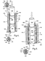
- thermoelectric module 142 is disposed within the sleeve 170 to create a temperature differential between the manifold 172 and the beverage container 168 to establish the desired temperature of the beverage container 168.
- the thermoelectric module 142 is annular in shape with the first surface 146 being in thermal contact with the inner wall 174 and the second surface 148 contacting the beverage container 168.
- the first surface 146 e.g., the hot surface 146, contacts the inner wall 174 to transfer heat from the first surface 146 to the coolant that is circulating through the annulus 178 of the manifold 172.
- the second surface 148 e.g., the cold surface 148, contacts the beverage container 168 to cool the beverage container 168, i.e., the second surface 148 is in thermal contact with the beverage container 168.
Abstract
Description
- The present invention relates to a thermoelectric heat transfer system for use in establishing a desired temperature in a climate-controlled area. More specifically, the present invention relates to the use of the thermoelectric heat transfer system for refrigeration of items such as beverage containers in coolers, vending machines, and the like.
- Thermoelectric heat transfer systems are well known for use in refrigeration. A typical thermoelectric heat transfer system includes at least one thermoelectric module to create a temperature differential. More specifically, when energized, heat moves across the thermoelectric module to form a hot surface and a cold surface. The cold surface provides the cooling needed for refrigeration.
- In recent years, improvements have been made to utilize coolant circuits to draw heat off of the hot surface of the thermoelectric module to further improve the efficiency of refrigeration. Referring to United States Patent No. 5,653,111 to Attey et al., a thermoelectric heat transfer system utilizing a coolant circuit for this purpose is shown. In Attey et al., the thermoelectric heat transfer system includes a pump in fluid communication with the coolant circuit to circulate coolant. A first heat exchanger is disposed in fluid communication with the coolant circuit to remove heat from the coolant being circulated. At the same time, a manifold is in fluid communication with the coolant circuit. An outer surface of the manifold is in contact with a hot surface of a thermoelectric module. By thermally connecting the coolant circuit with the hot surface of the thermoelectric module, the coolant can draw heat from the hot surface to improve the cooling efficiency of the thermoelectric module. The cold surface of the thermoelectric module is in contact with an outer surface of a second manifold to cool fluid flowing through the second manifold.
- Thermoelectric heat transfer systems for cooling beverage containers are also well known in the art. A typical heat transfer system for cooling a beverage container includes a sleeve adapted to receive the beverage container. In these systems, the thermoelectric module is disposed within the sleeve to create a temperature differential between the sleeve and the beverage container. More specifically, a hot surface of the thermoelectric module is in contact with the sleeve, while a cold surface of the thermoelectric module is in contact with the beverage container thereby drawing heat from the beverage container. A fan assembly draws heat away from the sleeve. An example of such a system is shown in United States Patent No. 6,530,232 to Kitchens.
- A thermoelectric heat transfer system is provided for establishing a desired temperature in a climate-controlled area. The system comprises a coolant circuit with a pump in fluid communication with the coolant circuit to circulate coolant. A first heat exchanger is in fluid communication with the coolant circuit to remove heat from the coolant. A second heat exchanger includes at least one thermally conductive conduit in fluid communication with the coolant circuit and at least one thermally conductive fin disposed outside of the coolant circuit. A thermoelectric module is disposed between the at least one conduit and the at least one fin to create a temperature differential between the at least one conduit and the at least one fin. A fan assembly is provided to convey air through the at least one fin into the climate-controlled area to establish the desired temperature within the climate-controlled area.
- One advantage of this thermoelectric heat transfer system is the integration of the thermoelectric module into the second heat exchanger. By integrating the thermoelectric module into the second heat exchanger, the fan assembly can simply convey ambient air through the second heat exchanger across the cooled fin into the climate-controlled area to cool the climate-controlled area.
- A thermoelectric heat transfer system for establishing a desired temperature of at least one item is also provided. This system also includes a coolant circuit with a pump in fluid communication with the coolant circuit to circulate coolant and a first heat exchanger in fluid communication with the coolant circuit to remove heat from the coolant. However, in this system, a sleeve is adapted to receive the at least one item. The sleeve includes a manifold in fluid communication with the coolant circuit. Here, a thermoelectric module is disposed within the sleeve to create a temperature differential between the manifold and the at least one item to establish the desired temperature of the at least one item.
- One advantage of this thermoelectric heat transfer system is the addition of the coolant circuit in a sleeve-type cooler. By using the coolant circuit with the first heat exchanger, greater cooling efficiency can be obtained for the system.
- Other advantages of the present invention will be readily appreciated, as the same becomes better understood by reference to the following detailed description when considered in connection with the accompanying drawings wherein:
- Figure 1 is a schematic view of a thermoelectric heat transfer system of the present invention;
- Figure 1A is a partial, cross-sectional perspective view of a heat exchanger of Fig. 1;
- Figure 2 is a cross-sectional view of a cooler incorporating the thermoelectric heat transfer system of Fig. 1 therein;
- Figure 3 is a schematic view of an alternative heat transfer system of the present invention;
- Figure 4 is a cross-sectional perspective view of a sleeve of the alternative heat transfer system; and
- Figure 5 is a cross-sectional perspective view of an alternative sleeve of the alternative heat transfer system; and
- Figure 6 is a cross-sectional view of a cooler incorporating the alternative heat transfer system.
- Referring to the Figures, wherein like numerals indicate like or corresponding parts throughout the several views, a thermoelectric heat transfer system for use in establishing a desired temperature in a climate-controlled area is shown generally at 10.
- Referring to the schematic view of FIG. 1, the thermoelectric
heat transfer system 10 comprises acoolant circuit 14 andpump 16 in fluid communication with thecoolant circuit 14 to circulate coolant. Preferably, the coolant being circulated is an environmentally friendly coolant such as a water-glycol solution. Of course, other coolants capable of heat transfer, including water, could also be used. - A
first heat exchanger 18 is in fluid communication with thecoolant circuit 14 to remove heat from the coolant being circulated. Thefirst heat exchanger 18 is a conventional air-cooledheat exchanger 18 similar to condensers found in automotive HVAC systems. Thefirst heat exchanger 18 includes aninlet tank 22 and anoutlet tank 24 in fluid communication with thecoolant circuit 14 and a plurality of flat, thermallyconductive conduits 25 or tubes fluidly interconnecting thetanks conductive fins 31 are disposed outside of thecoolant circuit 14. Each of theconvolutions 33 of thefins 31 includes a plurality of louvers (not shown). Preferably, theconduits 25 andfins 31 are alternately arranged in a stacked configuration. Thefins 31, which are well understood by those skilled in the art, are thermally conductive and are in thermal contact with theflat conduits 25 and the coolant flowing therethrough. As a result, heat from the coolant is transferred to thefins 31 and afan assembly 37 conveys air through thefins 31 to cool thefins 31 and thus, create a continuous flow of heat from the coolant to thefins 31 thereby removing heat from the coolant. - Referring to FIGS. 1 and 1A, a
second heat exchanger 40 is also in fluid communication with thecoolant circuit 14. Again, similar to thefirst heat exchanger 18, thesecond heat exchanger 40 includes asecond inlet tank 28 and asecond outlet tank 30 in fluid communication with thecoolant circuit 14 and a plurality of flat, thermallyconductive conduits 26 or tubes fluidly interconnecting thetanks conductive fins 32 are disposed outside of thecoolant circuit 14. Each of theconvolutions 34 of thefins 32 includes a plurality of louvers 36 (see FIG. 1A). Preferably, theconduits 26 andfins 32 of thesecond heat exchanger 40 are also alternately arranged in a stacked configuration. - Thermoelectric modules (TEMs) 42 are disposed between the
conduits 26 and thefins 32 of thesecond heat exchanger 40 to create a temperature differential between theconduits 26 and thefins 32. Each of theTEMs 42 includes a first thermallyconductive surface 46 in thermal contact with one of theconduits 26 and a second thermallyconductive surface 48 in thermal contact with one of thefins 32. Thefirst surface 46 is also referred to as thehot surface 46, and thesecond surface 48 is also referred to as thecold surface 48. The operation ofTEMs 42 is well known in the art and will not be described in detail. - Referring specifically to FIG. 1A, each of the
TEMs 42 comprises a pair of plates, afirst plate 43 presenting thehot surface 46 and asecond plate 45 presenting thecold surface 48. A plurality ofthermoelectric elements 50, i.e., N-type and P-typethermoelectric semiconductor elements 50, are arranged in an alternating N-element and P-element configuration between theplates thermoelectric elements 50 are coupled electrically in series and thermally in parallel. The Peltier effect occurs when voltage is applied to the N-type and the P-type elements 50 (a DC power source and switch shown in FIG. 1 are used to energize the TEMs 42) resulting in current flow through the serial electrical coupling. The serial current flow results in heat transfer across the N-type and P-type elements and across theplates - Referring back to FIG. 1, the
fins 32 extend generally between thetanks second heat exchanger 40 and theTEMs 42 extend between thetanks fins 32 and theconduits 26. Thefins 32,conduits 26, andTEMs 42 are arranged in the stacked configuration to maximize the cooling capacity of thesecond heat exchanger 40. Afan assembly 38 is adapted to convey air through the fins 32 (as shown by the arrows A in FIG. 1A) into the climate-controlled area 12 (see FIG. 2) to establish the desired temperature within the climate-controlledarea 12. - Referring to FIG. 2, a cooler 52 incorporating the thermoelectric
heat transfer system 10 is shown. The cooler 52 comprises ahousing 54 having afirst compartment 56 defining the climate-controlledarea 12 and asecond compartment 58 at least partially isolated from thefirst compartment 56. Thesecond heat exchanger 40 is laterally positioned in adivider wall 60 between thefirst compartment 56 and thesecond compartment 58. Thefan assembly 38, which is adapted to convey air through thesecond heat exchanger 40, is positioned in thesecond compartment 58. Ashroud 62 is fixed to thehousing 54 and supports thefan assembly 38 to direct air from thefan assembly 38 during operation through thefins 32 of thesecond heat exchanger 40 into the climate-controlledarea 12. The air may be primarily ambient air from outside of the housing 54 (which enters thesecond compartment 58 through multiple louvers 64) or the air may be a blend of ambient air and cooled air inside the climate-controlledarea 12. Apivotable mode door 66 is shown for controlling the blend by controlling the exit rate of cooled air from the climate-controlledarea 12 to thefan assembly 38 through asmall passage 67. Thefirst heat exchanger 18 is disposed in thesecond compartment 58 of thehousing 54 and itsfan assembly 37 is adapted to convey air through thefirst heat exchanger 18 to outside of thehousing 54 throughlouvers 65. - Preferably, the thermoelectric
heat transfer system 10 is used for refrigeration, i.e., cooling the climate-controlledarea 12. Nevertheless, in alternative embodiments, when the direction of current flow through thethermoelectric elements 50 is reversed (reverse polarity), thefirst plate 43 presents a cold surface and thesecond plate 45 presents a hot surface and the thermoelectricheat transfer system 10 can be used to heat the climate-controlledarea 12. In this instance, the hot surface would be in thermal contact with thefins 32 and the cold surface would be in thermal contact with theconduits 26. Thefan assembly 38 would then serve to convey ambient air across thefins 32 to heat the climate-controlledarea 12. In addition, thefirst heat exchanger 18 andfan assembly 37 would be employed to heat the coolant, as opposed to removing heat from the coolant, thereby increasing the heating capacity of thesecond heat exchanger 40. The principle of reversing the current flow through thermoelectric elements to switch between heating and cooling is well known to those skilled in the art and may be useful in heating the climate-controlledarea 12 to defrost the climate-controlledarea 12, or for other purposes. - A control system (not shown) including a microcontroller may be used to control the thermoelectric
heat transfer system 10. Preferably, the control system is operatively connected to theTEMs 42 to control theTEMs 42. The control system is also operatively connected to thefan assemblies mode door 66 to control their operation, e.g., conveying air, circulating coolant, varying air recirculation rates, etc. It should be appreciated that any conventional components could be utilized to control the thermoelectricheat transfer system 10, as will be appreciated by those skilled in the refrigeration arts. - An alternative thermoelectric
heat transfer system 110 is shown in the schematic view of FIG. 3. The alternative thermoelectricheat transfer system 110 is particularly well suited for cooling cylindrically-shapeditems 168 such asbeverage containers 168 to a desired temperature. Again, using like reference numerals increased by 100 to describe like parts, the alternativeheat transfer system 110 includes acoolant circuit 114 and apump 116 in fluid communication with thecoolant circuit 114 to circulate the coolant. Aheat exchanger 118 is in fluid communication with thecoolant circuit 114 to remove heat from the coolant being circulated. As before, afan assembly 137 conveys air through thefirst heat exchanger 118 to cool the coolant flowing through thefirst heat exchanger 118. - In this embodiment, however, instead of having a
second heat exchanger 40 with a configuration similar to the previous embodiment, asleeve 170 acts as the second heat exchanger. Thesleeve 170 is adapted to receive the cylindrically-shapeditems 168. Thesleeve 170 includes a manifold 172 that is in fluid communication with thecoolant circuit 114. The manifold 172 has a cylindrically-shapedinner wall 174 and a cylindrically-shapedouter wall 176 spaced radially outward from theinner wall 174 with anannulus 178 defined therebetween. Theouter wall 176 defines aninlet 180 and anoutlet 182 for passing the coolant through theannulus 178. - Here, the
thermoelectric module 142 is disposed within thesleeve 170 to create a temperature differential between the manifold 172 and thebeverage container 168 to establish the desired temperature of thebeverage container 168. Thethermoelectric module 142 is annular in shape with thefirst surface 146 being in thermal contact with theinner wall 174 and thesecond surface 148 contacting thebeverage container 168. Thefirst surface 146, e.g., thehot surface 146, contacts theinner wall 174 to transfer heat from thefirst surface 146 to the coolant that is circulating through theannulus 178 of themanifold 172. Thesecond surface 148, e.g., thecold surface 148, contacts thebeverage container 168 to cool thebeverage container 168, i.e., thesecond surface 148 is in thermal contact with thebeverage container 168. - Referring to FIG. 4, a thermally
conductive fin 132 is used to facilitate the transfer of heat from thefirst surface 146 to the coolant. Thefin 132 is disposed in theannulus 178 and wrapped about theinner wall 174. Preferably, thefin 132 is wrapped in a helical shape along a length of theinner wall 174 to transfer the heat from thefirst surface 146 to the coolant. It should be appreciated, that in other embodiments,multiple fins 132 wrapped about theinner wall 174 could also be employed. Here, thefin 132 is not only effective in providing a large surface area to draw heat from thefirst surface 146 of theTEM 142, thefin 132 is also effective in providing turbulence in the coolant flow from theinlet 180 to theoutlet 182 to further improve the efficiency of thesystem 110. - Still referring to FIG. 4, a second thermoelectric module (TEM) 144 adjoining the
first TEM 142 is disposed within thesleeve 170. Again, as with thefirst TEM 142, thesecond TEM 144 includes afirst plate 139 presenting afirst surface 147, e.g.,hot surface 147, in thermal contact with theinner wall 174 and asecond plate 141 presenting asecond surface 149, e.g.,cold surface 149, in thermal contact with thebeverage containers 168 with a plurality ofthermoelectric elements 151 disposed between theplates second TEM 144 is stacked above thefirst TEM 142 such that approximately one-half of thesleeve 170 is thermally controlled by thefirst TEM 142 and the other one-half is thermally controlled by thesecond TEM 144. Thesecond TEM 144 has a thermal capacity or rating that is different than a thermal capacity or rating of thefirst TEM 142. For this reason, as the plurality of the items 168 (here beverage containers 168) move through the sleeve 170 (such as in a vending machine in which the beverage cans cycle through the sleeve 170) one of thethermoelectric modules thermoelectric modules beverage containers 168 are moving through thesleeve 170 in the direction shown in FIG. 4, thesecond TEM 144 has a higher cooling capacity than thefirst TEM 142 to provide greater cooling of thebeverage containers 168 when first placed in thesleeve 170. - Referring to FIG. 5, an alternative sleeve 270 is shown for use in the alternative thermoelectric
heat transfer system 110. In this embodiment, the components of the thermoelectricheat transfer system 110 described with reference to FIG. 4 remain the same, except that areservoir 288 is now positioned between the first 142 and second 144 TEMs and thebeverage containers 168. In this embodiment, thereservoir 288 is filled with brine B to serve as a buffer and insulator for the beverage containers 268. Thereservoir 288 has anouter reservoir wall 290 in thermal contact with thesecond surface TEMs inner reservoir wall 292 in thermal contact with thebeverage containers 168. Thereservoir 288 assumes a similar annular shape to that of the manifold 172, complete with areservoir inlet 294 andreservoir outlet 296. However, theinlet 294 andoutlet 296 of thereservoir 288 merely serve to fill more brine B in thereservoir 288 and not for circulation. That is not to say, however, that in other embodiments, the brine could not be circulated. - Referring to FIG. 6, a
vending machine 86 incorporating the alternative thermoelectricheat transfer system 110 is shown. Thevending machine 86 includes ahousing 88 having afirst compartment 90 with a plurality of thesleeves 170 disposed therein and asecond compartment 92 at least partially isolated from thefirst compartment 90. Thesleeves 170 are oriented to facilitate the vending of thebeverage containers 168 therefrom. Thefirst heat exchanger 118 is disposed in thesecond compartment 92 and thefan assembly 137 is adapted to convey air through thefirst heat exchanger 118 to outside of thehousing 88 throughlouvers 94. Theinlets 180 andoutlets 182 of themanifolds 172 for each of thesleeves 170 are connected influid conduits 96 that extend to thefirst heat exchanger 118 and thepump 116, respectively. - The
fins conduits manifolds 172, andreservoir 288 are preferably formed from thermally conductive material such as metal, and more preferably, aluminum or copper. Theinlet outlet coolant circuits 14, 114 (including the fluid conduits 96) preferably comprise flexible hoses interconnecting theheat exchangers heat exchanger 118, pump 116, andmanifold 170 in FIG. 3. - Obviously, many modifications and variations of the present invention are possible in light of the above teachings. The invention may be practiced otherwise than as specifically described within the scope of the appended claims.
Claims (21)
- A thermoelectric heat transfer system (10) for use in establishing a desired temperature in a climate-controlled area (12), comprising:a coolant circuit (14),a pump (16) in fluid communication with said coolant circuit (14) for circulating coolant through said coolant circuit (14),a first heat exchanger (18) in fluid communication with said coolant circuit (14) for removing heat from the coolant being circulated through said coolant circuit (14),a second heat exchanger (40) having at least one thermally conductive conduit (26) in fluid communication with said coolant circuit (14) and at least one thermally conductive fin (32) disposed outside of said coolant circuit (14),a thermoelectric module (42) disposed between said at least one conduit (26) and said at least one fin (32) for creating a temperature differential between said at least one conduit (26) and said at least one fin (32), anda fan assembly (38) for conveying air through said at least one fin (32) into the climate-controlled area (12) to establish the desired temperature within the climate-controlled area (12).
- A thermoelectric heat transfer system (10) as set forth in claim 1 wherein said thermoelectric module (42) includes a first surface (46) in thermal contact with said at least one conduit (26) and a second surface (48) in thermal contact with said at least one fin (32).
- A thermoelectric heat transfer system (10) as set forth in claim 2 wherein said at least one fin (32) includes a plurality of convolutions (34) and a plurality of louvers (36) disposed along each of said convolutions (34).
- A thermoelectric heat transfer system (10) as set forth in claim 1 wherein said second heat exchanger (40) includes inlet (28) and outlet (30) tanks in fluid communication with said coolant circuit (14) and said at least one conduit (26) provides fluid communication between said tanks (28, 30) to pass the coolant from said inlet tank (28) to said outlet tank (30).
- A thermoelectric heat transfer system (10) as set forth in claim 4 wherein said at least one fin (32) extends between said tanks (28, 30) and said thermoelectric module (42) extends between said tanks (28, 30) sandwiched between said at least one fin (32) and said at least one conduit (26).
- A thermoelectric heat transfer system (10) as set forth in claim 1 wherein said at least one conduit (26) is further defined as a plurality of conduits (26) in fluid communication with said coolant circuit (14) and said at least one fin (32) is further defined as a plurality of fins (32) with said conduits (26) and said fms (32) being alternately arranged in a stacked configuration.
- A thermoelectric heat transfer system (10) as set forth in claim 6 including a plurality of thermoelectric modules (42) with each of said thermoelectric modules (42) disposed between one of said conduits (26) and one of said fins (32) in said stacked configuration.
- A thermoelectric heat transfer system (10) as set forth in claim 7 including a second fan assembly (37) for conveying air through said first heat exchanger (18) to cool the coolant flowing through said first heat exchanger (18).
- A thermoelectric heat transfer system (10) as set forth in claim 8 including a housing (54) having a first compartment (56) for defining the climate-controlled area (12) and a second compartment (58) at least partially isolated from said first compartment (56) with said fan assembly (38) being adapted to convey the air through said plurality of fins (32) into said first compartment (56).
- A thermoelectric heat transfer system (10) as set forth in claim 9 wherein said first heat exchanger (18) is disposed in said second compartment (58) and said second fan assembly (37) is adapted to convey the air through said first heat exchanger (18) to outside of said housing (54).
- A thermoelectric heat transfer system (110) for establishing a desired temperature of at least one item (168), comprising:a coolant circuit (114),a pump (116) in fluid communication with said coolant circuit (114) for circulating coolant through said coolant circuit (114),a first heat exchanger (118) in fluid communication with said coolant circuit (114) for removing heat from the coolant being circulated through said coolant circuit (114),a sleeve (170) adapted to receive the at least one item and including a manifold (172) in fluid communication with said coolant circuit (114), anda thermoelectric module (142) disposed within said sleeve (170) for creating a temperature differential between said manifold (172) and the at least one item (168) to establish the desired temperature of the at least one item (168).
- A thermoelectric heat transfer system (110) as set forth in claim 11 wherein said manifold (172) includes an inner wall (174) and an outer wall (176) with an annulus (178) defined therebetween and said outer wall (176) defines an inlet (180) and an outlet (182) for passing the coolant through said annulus (178).
- A thermoelectric heat transfer system (110) as set forth in claim 12 wherein said thermoelectric module (142) is annular in shape and said thermoelectric module (142) includes a first surface (146) in thermal contact with said inner wall (174) and a second surface (148) adapted for being in thermal contact with the at least one item (168).
- A thermoelectric heat transfer system (110) as set forth in claim 13 including a second thermoelectric module (144) adjoining said other thermoelectric module (142) wherein said second thermoelectric module (144) includes a first surface (147) in thermal contact with said inner wall (174) and a second surface (149) adapted for being in thermal contact with the at least one item (168).
- A thermoelectric heat transfer system (110) as set forth in claim 14 wherein said second thermoelectric module (144) has a thermal capacity that is different than a thermal capacity of said other thermoelectric module (142) such that as a plurality of the items (168) move through said sleeve (170) one of said thermoelectric modules (142, 144) are capable of providing greater cooling capacity than the other of said thermoelectric modules (142, 144).
- A thermoelectric heat transfer system (110) as set forth in claim 13 including at least one thermally conductive fin (132) wrapped about said inner wall (174) in said annulus (178).
- A thermoelectric heat transfer system (110) as set forth in claim 16 wherein said at least one fin (132) is wrapped in a helical shape along a length of said inner wall (174) for transferring heat from said first surface (146) to the coolant.
- A thermoelectric heat transfer system (10) as set forth in claim 13 including a reservoir (288) having an outer wall (290) in thermal contact with said second surface (148) and an inner wall (292) adapted for being in thermal contact with the at least one item (168).
- A thermoelectric heat transfer system (110) as set forth in claim 18 wherein said reservoir (288) is filled with brine whereby said second surface (148) and said brine are in thermal contact with the at least one item (168) to cool the at least one item (168).
- A thermoelectric heat transfer system (110) as set forth in claim 11 including a fan assembly (137) for conveying air through said first heat exchanger (118) to cool the coolant flowing through said first heat exchanger (118).
- A thermoelectric heat transfer system (110) as set forth in claim 20 including a housing (88) having a first compartment (90) with a plurality of said sleeves (170) disposed therein and a second compartment (92) at least partially isolated from said first compartment (90) with said first heat exchanger (118) being disposed in said second compartment (92) and said fan assembly (137) being adapted to convey the air through said first heat exchanger (118) to outside of said housing (88).
Applications Claiming Priority (1)
| Application Number | Priority Date | Filing Date | Title |
|---|---|---|---|
| US11/041,819 US7650757B2 (en) | 2005-01-24 | 2005-01-24 | Thermoelectric heat transfer system |
Publications (2)
| Publication Number | Publication Date |
|---|---|
| EP1684031A2 true EP1684031A2 (en) | 2006-07-26 |
| EP1684031A3 EP1684031A3 (en) | 2012-01-04 |
Family
ID=36481384
Family Applications (1)
| Application Number | Title | Priority Date | Filing Date |
|---|---|---|---|
| EP06075051A Withdrawn EP1684031A3 (en) | 2005-01-24 | 2006-01-11 | Thermoelectric heat transfer system |
Country Status (2)
| Country | Link |
|---|---|
| US (1) | US7650757B2 (en) |
| EP (1) | EP1684031A3 (en) |
Cited By (9)
| Publication number | Priority date | Publication date | Assignee | Title |
|---|---|---|---|---|
| GB2442864A (en) * | 2006-10-13 | 2008-04-16 | Dell Products Lp | Hybrid heat exchanger |
| US7564683B2 (en) | 2007-08-30 | 2009-07-21 | Dell Products, Lp | Cooling subsystem with easily adjustable mounting assembly |
| WO2010008611A2 (en) | 2008-07-18 | 2010-01-21 | Greenbev, Llc. | On demand consumable product heating and/or cooling dispenser |
| US7893635B2 (en) | 2008-05-08 | 2011-02-22 | Dell Products, Lp | Liquid cooling system with automatic pump speed control |
| EP2420769A3 (en) * | 2010-08-03 | 2014-02-26 | Whirlpool Corporation | Turbo-chill chamber with air-flow booster |
| EP2778589A3 (en) * | 2013-03-12 | 2015-06-10 | Hussmann Corporation | Thermoelectric power generation condenser |
| CN104888483A (en) * | 2015-06-14 | 2015-09-09 | 李景峰 | External cooling type electronic condensation water distilling apparatus without cooling water |
| US9448006B2 (en) | 2010-08-03 | 2016-09-20 | Whirlpool Corporation | Turbo-chill chamber using secondary coolant |
| DE102014110281B4 (en) | 2013-12-23 | 2022-05-12 | Hanon Systems | Heat exchanger and method of making the same |
Families Citing this family (23)
| Publication number | Priority date | Publication date | Assignee | Title |
|---|---|---|---|---|
| US7380586B2 (en) | 2004-05-10 | 2008-06-03 | Bsst Llc | Climate control system for hybrid vehicles using thermoelectric devices |
| US7743614B2 (en) | 2005-04-08 | 2010-06-29 | Bsst Llc | Thermoelectric-based heating and cooling system |
| US20080066874A1 (en) * | 2006-09-19 | 2008-03-20 | Mohinder Singh Bhatti | High efficiency water desalinator |
| WO2008148042A2 (en) | 2007-05-25 | 2008-12-04 | Bsst Llc | System and method for distributed thermoelectric heating and colling |
| WO2009055066A1 (en) | 2007-10-25 | 2009-04-30 | Paradise Smoothies, Inc. | Apparatus for mixing, cooling, and dispensing a containerized beverage |
| JP5033743B2 (en) * | 2008-09-18 | 2012-09-26 | 株式会社テックスイージー | Container temperature control device |
| US9555686B2 (en) | 2008-10-23 | 2017-01-31 | Gentherm Incorporated | Temperature control systems with thermoelectric devices |
| US9447994B2 (en) | 2008-10-23 | 2016-09-20 | Gentherm Incorporated | Temperature control systems with thermoelectric devices |
| US20100258268A1 (en) * | 2009-04-12 | 2010-10-14 | Hsin-Jen Li | Temperature adjustable cup holder having memory card readable function |
| EP2433192B2 (en) | 2009-05-18 | 2020-08-26 | Gentherm Incorporated | Temperature control system with thermoelectric device |
| EP2552747A1 (en) * | 2010-03-30 | 2013-02-06 | Behr GmbH & Co. KG | Temperature control element and temperature control device for a vehicle |
| US20120193070A1 (en) * | 2011-02-01 | 2012-08-02 | Adrian Ryan Lynn | Drinkware conditioner |
| US8397518B1 (en) | 2012-02-20 | 2013-03-19 | Dhama Innovations PVT. Ltd. | Apparel with integral heating and cooling device |
| US9518766B2 (en) * | 2013-03-15 | 2016-12-13 | Altria Client Services Llc | Method and system for thermoelectric cooling of products on display at retail |
| US20150323228A1 (en) * | 2014-05-08 | 2015-11-12 | Delphi Technologies, Inc. | Heat Exchanger Having a Plurality of Thermoelectric Modules Connected in Series |
| USD781356S1 (en) | 2014-04-04 | 2017-03-14 | Jonathan James Iungerich | Finned tube |
| CN107249910B (en) | 2014-12-19 | 2021-01-15 | 詹思姆公司 | Thermal conditioning system and method for a vehicle area |
| US10492603B2 (en) * | 2015-05-19 | 2019-12-03 | The Boeing Company | Systems and methods of cooling a galley of an aircraft |
| US10625566B2 (en) | 2015-10-14 | 2020-04-21 | Gentherm Incorporated | Systems and methods for controlling thermal conditioning of vehicle regions |
| US9982950B2 (en) * | 2015-12-11 | 2018-05-29 | Winston MacKelvie | Concentric vertical pipe heat exchanger for drain water heat recovery |
| GB2566191B (en) | 2016-05-18 | 2021-01-20 | Walmart Apollo Llc | Evaporative cooling systems and methods of controlling product temperatures during delivery |
| CA3031453A1 (en) | 2016-07-27 | 2018-02-01 | Walmart Apollo, Llc | Systems and methods for delivering perishable items |
| GB2569510A (en) | 2016-10-04 | 2019-06-19 | Walmart Apollo Llc | Systems and methods utilizing nanotechnology insulation materials in limiting temperature changes during product delivery |
Citations (2)
| Publication number | Priority date | Publication date | Assignee | Title |
|---|---|---|---|---|
| US5653111A (en) | 1993-07-07 | 1997-08-05 | Hydrocool Pty. Ltd. | Thermoelectric refrigeration with liquid heat exchange |
| US6530232B1 (en) | 2002-06-10 | 2003-03-11 | Mark Kitchens | Thermoelectric sleeve-type beverage insulator apparatus |
Family Cites Families (24)
| Publication number | Priority date | Publication date | Assignee | Title |
|---|---|---|---|---|
| US531078A (en) * | 1894-12-18 | Thomas | ||
| US1993171A (en) * | 1931-12-15 | 1935-03-05 | Mc Cord Radiator And Mfg Compa | Cooling unit for refrigerators |
| US3097027A (en) * | 1961-03-21 | 1963-07-09 | Barden Corp | Thermoelectric cooling assembly |
| US4517815A (en) * | 1983-10-07 | 1985-05-21 | Basso Peter J | Insulated modular cooler |
| US5038569A (en) * | 1989-04-17 | 1991-08-13 | Nippondenso Co., Ltd. | Thermoelectric converter |
| US5362145A (en) * | 1991-03-07 | 1994-11-08 | Donnelly Corporation | Molded refrigerator shelf |
| US5454638A (en) * | 1991-03-07 | 1995-10-03 | Donnelly Technology, Inc. | Adjustable refrigerator shelving |
| US5540493A (en) * | 1991-03-07 | 1996-07-30 | Donnelly Technology Inc. | Encapsulated shelf with pre-encapsulated bracket |
| US5273354A (en) * | 1991-03-07 | 1993-12-28 | Donnelly Corporation | Molded refrigerator shelf and support bracket |
| US5441338A (en) * | 1991-03-07 | 1995-08-15 | Donnelly Corporation | Snap-on shelf |
| US5403084A (en) * | 1991-03-07 | 1995-04-04 | Donnelly Corporation | Molded refrigerator shelf with snap-in slide |
| CA2090998C (en) | 1992-05-21 | 2000-11-28 | Anthony Joseph Cesaroni | Panel heat exchanger with integral thermoelectric device |
| AU5683294A (en) * | 1992-11-27 | 1994-06-22 | Pneumo Abex Corporation | Thermoelectric device for heating and cooling air for human use |
| CA2146791C (en) * | 1994-04-29 | 2002-06-25 | Robert S. Herrmann | Sliding refrigerator shelf assembly |
| US5737923A (en) * | 1995-10-17 | 1998-04-14 | Marlow Industries, Inc. | Thermoelectric device with evaporating/condensing heat exchanger |
| GB2322732A (en) | 1997-02-24 | 1998-09-02 | W S Atkins Consultants Limited | Controlling the temperature of dispensed liquids |
| RU2114010C1 (en) * | 1997-08-20 | 1998-06-27 | Петрыкин Евгений Алексеевич | Vehicle air conditioner |
| US6082114A (en) * | 1998-04-09 | 2000-07-04 | Leonoff; Christopher A. | Device for heating and cooling a beverage |
| IT1309710B1 (en) * | 1999-02-19 | 2002-01-30 | Pastorino Giorgio | SOLID STATE THERMOELECTRIC DEVICE |
| US6106058A (en) * | 1999-06-18 | 2000-08-22 | Kenneth C. Sur | Chair or sofa with refrigerated compartment |
| US6266963B1 (en) * | 1999-10-05 | 2001-07-31 | The Coca-Cola Company | Apparatus using stirling cooler system and methods of use |
| JP2001116424A (en) * | 1999-10-22 | 2001-04-27 | Matsushita Refrig Co Ltd | Cooling storage cabinet |
| KR100493295B1 (en) * | 2002-02-07 | 2005-06-03 | 엘지전자 주식회사 | Air-conditioner using thermoelectric module |
| US7089749B1 (en) * | 2003-08-20 | 2006-08-15 | Robin Contino | Thermoelectrically heated/cooled cupholder system |
-
2005
- 2005-01-24 US US11/041,819 patent/US7650757B2/en not_active Expired - Fee Related
-
2006
- 2006-01-11 EP EP06075051A patent/EP1684031A3/en not_active Withdrawn
Patent Citations (2)
| Publication number | Priority date | Publication date | Assignee | Title |
|---|---|---|---|---|
| US5653111A (en) | 1993-07-07 | 1997-08-05 | Hydrocool Pty. Ltd. | Thermoelectric refrigeration with liquid heat exchange |
| US6530232B1 (en) | 2002-06-10 | 2003-03-11 | Mark Kitchens | Thermoelectric sleeve-type beverage insulator apparatus |
Cited By (17)
| Publication number | Priority date | Publication date | Assignee | Title |
|---|---|---|---|---|
| TWI386154B (en) * | 2006-10-13 | 2013-02-11 | Dell Products Lp | Hybrid heat exchanger |
| GB2442864B (en) * | 2006-10-13 | 2009-08-19 | Dell Products Lp | Hybrid heat exchanger |
| DE102007048645B4 (en) * | 2006-10-13 | 2020-03-12 | Dell Products L.P. | Hybrid heat exchanger |
| GB2442864A (en) * | 2006-10-13 | 2008-04-16 | Dell Products Lp | Hybrid heat exchanger |
| US9588554B2 (en) | 2006-10-13 | 2017-03-07 | Dell Products, Lp | Hybrid heat exchanger |
| US8453467B2 (en) | 2006-10-13 | 2013-06-04 | Dell Products, Lp | Hybrid heat exchanger |
| US7564683B2 (en) | 2007-08-30 | 2009-07-21 | Dell Products, Lp | Cooling subsystem with easily adjustable mounting assembly |
| US7893635B2 (en) | 2008-05-08 | 2011-02-22 | Dell Products, Lp | Liquid cooling system with automatic pump speed control |
| EP2321805A4 (en) * | 2008-07-18 | 2013-01-23 | Greenbev Llc | On demand consumable product heating and/or cooling dispenser |
| CN102165498A (en) * | 2008-07-18 | 2011-08-24 | 格林贝夫有限责任公司 | On demand consumable product heating and/or cooling dispenser |
| EP2321805A2 (en) * | 2008-07-18 | 2011-05-18 | Greenbev, Llc. | On demand consumable product heating and/or cooling dispenser |
| WO2010008611A2 (en) | 2008-07-18 | 2010-01-21 | Greenbev, Llc. | On demand consumable product heating and/or cooling dispenser |
| EP2420769A3 (en) * | 2010-08-03 | 2014-02-26 | Whirlpool Corporation | Turbo-chill chamber with air-flow booster |
| US9448006B2 (en) | 2010-08-03 | 2016-09-20 | Whirlpool Corporation | Turbo-chill chamber using secondary coolant |
| EP2778589A3 (en) * | 2013-03-12 | 2015-06-10 | Hussmann Corporation | Thermoelectric power generation condenser |
| DE102014110281B4 (en) | 2013-12-23 | 2022-05-12 | Hanon Systems | Heat exchanger and method of making the same |
| CN104888483A (en) * | 2015-06-14 | 2015-09-09 | 李景峰 | External cooling type electronic condensation water distilling apparatus without cooling water |
Also Published As
| Publication number | Publication date |
|---|---|
| EP1684031A3 (en) | 2012-01-04 |
| US20060162342A1 (en) | 2006-07-27 |
| US7650757B2 (en) | 2010-01-26 |
Similar Documents
| Publication | Publication Date | Title |
|---|---|---|
| US7650757B2 (en) | Thermoelectric heat transfer system | |
| US5544487A (en) | Thermoelectric heat pump w/hot & cold liquid heat exchange circutis | |
| US20200276882A1 (en) | Cooling System for a Motor Vehicle and Motor Vehicle Having Such a Cooling System | |
| CN102395850B (en) | For the temperature control system of liquid | |
| US10327722B2 (en) | Systems and methods for cooling X-ray tubes and detectors | |
| CN202598944U (en) | Thermoelectric type heat exchanger capable of providing two different discharging temperatures | |
| CN1172934A (en) | Food storage device employing thermoelectric element as heat source and sink | |
| SE440554B (en) | HEAT EXCHANGER DEVICE WITH STORAGE SYSTEM | |
| CN107704054A (en) | The cooling system cooled down to electronic component | |
| US11648822B2 (en) | Heat management device | |
| US3287923A (en) | Thermoelectric assembly | |
| US11353273B2 (en) | Heat exchanger module and a housing therefor | |
| CN206884725U (en) | The heat management system and vehicle of vehicle | |
| EP2642221A2 (en) | Refrigerator | |
| CN210000061U (en) | Thermal management system of electric automobile | |
| WO2004016991A1 (en) | Apparatus and method for exchanging heat | |
| KR102393486B1 (en) | Cooling device | |
| KR102358931B1 (en) | Heat exchanger | |
| KR20110133154A (en) | Integrated radiator | |
| CN218616342U (en) | Battery thermal management system and vehicle | |
| CN219999866U (en) | Heat dissipation enhanced fluid heat dissipation device | |
| KR20130106487A (en) | Thermoelectric power generating system | |
| CN211345920U (en) | Small-size cabinet type industrial refrigeration heating all-in-one | |
| CN218511263U (en) | Binary heat exchange semiconductor refrigerator | |
| CN219756686U (en) | System for cooling electronic refrigeration piece hot end by adopting fluid |
Legal Events
| Date | Code | Title | Description |
|---|---|---|---|
| PUAI | Public reference made under article 153(3) epc to a published international application that has entered the european phase |
Free format text: ORIGINAL CODE: 0009012 |
|
| AK | Designated contracting states |
Kind code of ref document: A2 Designated state(s): AT BE BG CH CY CZ DE DK EE ES FI FR GB GR HU IE IS IT LI LT LU LV MC NL PL PT RO SE SI SK TR |
|
| AX | Request for extension of the european patent |
Extension state: AL BA HR MK YU |
|
| RIC1 | Information provided on ipc code assigned before grant |
Ipc: F25D 17/06 20060101ALN20110923BHEP Ipc: F25D 31/00 20060101ALI20110923BHEP Ipc: F25D 11/00 20060101ALI20110923BHEP Ipc: F25B 25/00 20060101ALI20110923BHEP Ipc: F25B 21/02 20060101AFI20110923BHEP |
|
| PUAL | Search report despatched |
Free format text: ORIGINAL CODE: 0009013 |
|
| AK | Designated contracting states |
Kind code of ref document: A3 Designated state(s): AT BE BG CH CY CZ DE DK EE ES FI FR GB GR HU IE IS IT LI LT LU LV MC NL PL PT RO SE SI SK TR |
|
| AX | Request for extension of the european patent |
Extension state: AL BA HR MK YU |
|
| RIC1 | Information provided on ipc code assigned before grant |
Ipc: F25D 17/06 20060101ALN20111129BHEP Ipc: F25D 31/00 20060101ALI20111129BHEP Ipc: F25D 11/00 20060101ALI20111129BHEP Ipc: F25B 25/00 20060101ALI20111129BHEP Ipc: F25B 21/02 20060101AFI20111129BHEP |
|
| STAA | Information on the status of an ep patent application or granted ep patent |
Free format text: STATUS: THE APPLICATION IS DEEMED TO BE WITHDRAWN |
|
| 18D | Application deemed to be withdrawn |
Effective date: 20110802 |