EP1684004A1 - Projecteur de véhicule automobile avec deux faisceaux d'éclairage - Google Patents
Projecteur de véhicule automobile avec deux faisceaux d'éclairage Download PDFInfo
- Publication number
- EP1684004A1 EP1684004A1 EP06290112A EP06290112A EP1684004A1 EP 1684004 A1 EP1684004 A1 EP 1684004A1 EP 06290112 A EP06290112 A EP 06290112A EP 06290112 A EP06290112 A EP 06290112A EP 1684004 A1 EP1684004 A1 EP 1684004A1
- Authority
- EP
- European Patent Office
- Prior art keywords
- optical module
- module according
- mirror
- reflecting mirror
- source
- Prior art date
- Legal status (The legal status is an assumption and is not a legal conclusion. Google has not performed a legal analysis and makes no representation as to the accuracy of the status listed.)
- Granted
Links
- 230000003287 optical effect Effects 0.000 claims abstract description 77
- 238000005286 illumination Methods 0.000 claims description 16
- 230000004907 flux Effects 0.000 description 3
- 238000004519 manufacturing process Methods 0.000 description 3
- 239000012141 concentrate Substances 0.000 description 1
- 238000010586 diagram Methods 0.000 description 1
- 238000006073 displacement reaction Methods 0.000 description 1
- 230000002452 interceptive effect Effects 0.000 description 1
- 230000004048 modification Effects 0.000 description 1
- 238000012986 modification Methods 0.000 description 1
- 238000011084 recovery Methods 0.000 description 1
- 230000000630 rising effect Effects 0.000 description 1
Images

Classifications
-
- F—MECHANICAL ENGINEERING; LIGHTING; HEATING; WEAPONS; BLASTING
- F21—LIGHTING
- F21S—NON-PORTABLE LIGHTING DEVICES; SYSTEMS THEREOF; VEHICLE LIGHTING DEVICES SPECIALLY ADAPTED FOR VEHICLE EXTERIORS
- F21S41/00—Illuminating devices specially adapted for vehicle exteriors, e.g. headlamps
- F21S41/20—Illuminating devices specially adapted for vehicle exteriors, e.g. headlamps characterised by refractors, transparent cover plates, light guides or filters
- F21S41/25—Projection lenses
- F21S41/255—Lenses with a front view of circular or truncated circular outline
-
- F—MECHANICAL ENGINEERING; LIGHTING; HEATING; WEAPONS; BLASTING
- F21—LIGHTING
- F21S—NON-PORTABLE LIGHTING DEVICES; SYSTEMS THEREOF; VEHICLE LIGHTING DEVICES SPECIALLY ADAPTED FOR VEHICLE EXTERIORS
- F21S41/00—Illuminating devices specially adapted for vehicle exteriors, e.g. headlamps
- F21S41/30—Illuminating devices specially adapted for vehicle exteriors, e.g. headlamps characterised by reflectors
- F21S41/32—Optical layout thereof
- F21S41/36—Combinations of two or more separate reflectors
-
- F—MECHANICAL ENGINEERING; LIGHTING; HEATING; WEAPONS; BLASTING
- F21—LIGHTING
- F21S—NON-PORTABLE LIGHTING DEVICES; SYSTEMS THEREOF; VEHICLE LIGHTING DEVICES SPECIALLY ADAPTED FOR VEHICLE EXTERIORS
- F21S41/00—Illuminating devices specially adapted for vehicle exteriors, e.g. headlamps
-
- F—MECHANICAL ENGINEERING; LIGHTING; HEATING; WEAPONS; BLASTING
- F21—LIGHTING
- F21S—NON-PORTABLE LIGHTING DEVICES; SYSTEMS THEREOF; VEHICLE LIGHTING DEVICES SPECIALLY ADAPTED FOR VEHICLE EXTERIORS
- F21S41/00—Illuminating devices specially adapted for vehicle exteriors, e.g. headlamps
- F21S41/30—Illuminating devices specially adapted for vehicle exteriors, e.g. headlamps characterised by reflectors
- F21S41/32—Optical layout thereof
- F21S41/321—Optical layout thereof the reflector being a surface of revolution or a planar surface, e.g. truncated
-
- F—MECHANICAL ENGINEERING; LIGHTING; HEATING; WEAPONS; BLASTING
- F21—LIGHTING
- F21S—NON-PORTABLE LIGHTING DEVICES; SYSTEMS THEREOF; VEHICLE LIGHTING DEVICES SPECIALLY ADAPTED FOR VEHICLE EXTERIORS
- F21S41/00—Illuminating devices specially adapted for vehicle exteriors, e.g. headlamps
- F21S41/40—Illuminating devices specially adapted for vehicle exteriors, e.g. headlamps characterised by screens, non-reflecting members, light-shielding members or fixed shades
- F21S41/43—Illuminating devices specially adapted for vehicle exteriors, e.g. headlamps characterised by screens, non-reflecting members, light-shielding members or fixed shades characterised by the shape thereof
-
- F—MECHANICAL ENGINEERING; LIGHTING; HEATING; WEAPONS; BLASTING
- F21—LIGHTING
- F21S—NON-PORTABLE LIGHTING DEVICES; SYSTEMS THEREOF; VEHICLE LIGHTING DEVICES SPECIALLY ADAPTED FOR VEHICLE EXTERIORS
- F21S41/00—Illuminating devices specially adapted for vehicle exteriors, e.g. headlamps
- F21S41/60—Illuminating devices specially adapted for vehicle exteriors, e.g. headlamps characterised by a variable light distribution
- F21S41/67—Illuminating devices specially adapted for vehicle exteriors, e.g. headlamps characterised by a variable light distribution by acting on reflectors
- F21S41/675—Illuminating devices specially adapted for vehicle exteriors, e.g. headlamps characterised by a variable light distribution by acting on reflectors by moving reflectors
-
- F—MECHANICAL ENGINEERING; LIGHTING; HEATING; WEAPONS; BLASTING
- F21—LIGHTING
- F21S—NON-PORTABLE LIGHTING DEVICES; SYSTEMS THEREOF; VEHICLE LIGHTING DEVICES SPECIALLY ADAPTED FOR VEHICLE EXTERIORS
- F21S41/00—Illuminating devices specially adapted for vehicle exteriors, e.g. headlamps
- F21S41/60—Illuminating devices specially adapted for vehicle exteriors, e.g. headlamps characterised by a variable light distribution
- F21S41/68—Illuminating devices specially adapted for vehicle exteriors, e.g. headlamps characterised by a variable light distribution by acting on screens
- F21S41/683—Illuminating devices specially adapted for vehicle exteriors, e.g. headlamps characterised by a variable light distribution by acting on screens by moving screens
- F21S41/686—Blades, i.e. screens moving in a vertical plane
-
- F—MECHANICAL ENGINEERING; LIGHTING; HEATING; WEAPONS; BLASTING
- F21—LIGHTING
- F21S—NON-PORTABLE LIGHTING DEVICES; SYSTEMS THEREOF; VEHICLE LIGHTING DEVICES SPECIALLY ADAPTED FOR VEHICLE EXTERIORS
- F21S43/00—Signalling devices specially adapted for vehicle exteriors, e.g. brake lamps, direction indicator lights or reversing lights
- F21S43/20—Signalling devices specially adapted for vehicle exteriors, e.g. brake lamps, direction indicator lights or reversing lights characterised by refractors, transparent cover plates, light guides or filters
- F21S43/26—Refractors, transparent cover plates, light guides or filters not provided in groups F21S43/235 - F21S43/255
-
- F—MECHANICAL ENGINEERING; LIGHTING; HEATING; WEAPONS; BLASTING
- F21—LIGHTING
- F21S—NON-PORTABLE LIGHTING DEVICES; SYSTEMS THEREOF; VEHICLE LIGHTING DEVICES SPECIALLY ADAPTED FOR VEHICLE EXTERIORS
- F21S43/00—Signalling devices specially adapted for vehicle exteriors, e.g. brake lamps, direction indicator lights or reversing lights
- F21S43/30—Signalling devices specially adapted for vehicle exteriors, e.g. brake lamps, direction indicator lights or reversing lights characterised by reflectors
- F21S43/31—Optical layout thereof
-
- F—MECHANICAL ENGINEERING; LIGHTING; HEATING; WEAPONS; BLASTING
- F21—LIGHTING
- F21S—NON-PORTABLE LIGHTING DEVICES; SYSTEMS THEREOF; VEHICLE LIGHTING DEVICES SPECIALLY ADAPTED FOR VEHICLE EXTERIORS
- F21S43/00—Signalling devices specially adapted for vehicle exteriors, e.g. brake lamps, direction indicator lights or reversing lights
- F21S43/40—Signalling devices specially adapted for vehicle exteriors, e.g. brake lamps, direction indicator lights or reversing lights characterised by the combination of reflectors and refractors
-
- F—MECHANICAL ENGINEERING; LIGHTING; HEATING; WEAPONS; BLASTING
- F21—LIGHTING
- F21W—INDEXING SCHEME ASSOCIATED WITH SUBCLASSES F21K, F21L, F21S and F21V, RELATING TO USES OR APPLICATIONS OF LIGHTING DEVICES OR SYSTEMS
- F21W2103/00—Exterior vehicle lighting devices for signalling purposes
- F21W2103/10—Position lights
Definitions
- An optical module of this type known from FR-A-2 840 389, makes it possible to produce an infrared secondary illumination beam in an area situated above the cutoff, by means of a diffuser fixed on the front face of the cache.
- the illumination range of the secondary beam is located substantially above the optical axis and is off-center with respect to this axis.
- the illumination grid that is to say the area illuminated on a screen situated at a predetermined distance from the spotlight and orthogonal to the optical axis, must be rectangular , centered on the optical axis between defined limits.
- the object of the invention is, above all, to provide a luminous headlamp, with a main beam of cut-off lighting, which makes it possible to ensure at least one additional secondary function of the city lamp or DRL type, without interfering with the main function.
- an optical module of the kind defined above comprises a retractable return mirror that can pass from a retracted position, where the mirror does not substantially interfere with the beam principle, at a working position in which the reflecting mirror is in the vicinity of the focal plane of the lens, substantially centered on the optical axis and oriented so as to give, from the light rays issuing from the secondary source, a secondary beam, preferably substantially centered on the optical axis, and constituting the secondary function of illumination.
- the light rays "derived" from the secondary source can reach the reflecting mirror directly and / or indirectly (that is to say having possibly previously undergone at least one modification of their initial trajectory, for example by at least one prior reflection on another reflective surface.)
- this beam conforms to a substantially rectangular illumination grid
- the reflecting mirror may be substantially flat, in particular rectangular.
- the long side of the reflecting mirror can be substantially horizontal.
- the projector's cover is fixed and the reflecting mirror, in its working position, is in front of the cover.
- the cover is movably mounted, in translation or in rotation, and is erased to allow the introduction of the deflection mirror in the working position.
- the cover is movably mounted makes it possible to confer on the optical module several so-called main functions with the same light source: it is possible to provide a cover, which, in the retracted / retracted position, makes it possible to obtain a beam-type unbroken beam. and which, in working position, makes it possible to obtain at least one code-beam, fog-beam or other cut-off beam defined by the new functions AFS for the abbreviation Advanced Front Systems.
- movable caches for obtaining at least two different main functions are for example described in patent FR 04/06273 filed 09/06/04, with a cache having an "active" edge composed of a set of portions distinct, at least a portion of one of the portions of the set of portions involved in the production of at least two different cuts of the light beam emitted by said light source, or the patent EP 1 197 387.
- the main source can generate a road-type beam with the cover in position and the reflecting mirror in both retracted positions (that is to say both inactive vis-à-vis the light rays emitted by the main source).
- the reflecting mirror can then be placed in front of the cache or be integrated therewith.
- the module according to the invention is therefore able to emit at least one cut-off main beam, in particular chosen from the code and fog beams. It is also capable of generating another main beam with or without cutoff, in particular of the road beam type.
- the secondary function is preferably a city lamp and / or DRL function.
- the secondary source may be located in the vertical plane passing through the optical axis and be spaced transversely of this axis; the reflecting mirror, in its working position, is inclined towards the secondary source with respect to the optical axis.
- the secondary source can be supplied in a variable way: one can have a power supply which varies according to whether one wants a function of the type DRL (maximum power) or a city lamp function (reduced power): the source can thus make it possible to 'get two different functions by itself depending on how it is powered (under voltage or not).
- the angle of inclination is such that the image of the secondary source given by the reflecting mirror is directed towards the lens. It may be on the optical axis or in the vicinity of this optical axis, but it is not a necessary condition.
- the center of the deflection mirror is advantageously in the vicinity of the focus of the lens.
- the secondary source can be oriented so as to directly illuminate the reflecting mirror including to provide a secondary function city lamp, while the main source is off.
- the secondary source is advantageously oriented so as to illuminate opposite the reflecting mirror, to a fixed concave recuperating mirror which reflects and concentrates the light on the reflecting mirror.
- the secondary source has a flow sufficient to provide a secondary function DRL, it is possible to provide another secondary function city lamp by a sub-voltage supply of the secondary source.
- the deflection mirror may be rotatably mounted about an axis orthogonal to the plane passing through the optical axis and the center of the secondary source, and discarded transversely of the optical axis.
- the cache can be mounted movably, in which case the reflecting mirror can be secured to the cache.
- the cover can move from an active position corresponding to the main function with retraction of the deflection mirror, to an inactive position corresponding to the secondary function with reflecting mirror in working position, and vice versa.
- the invention also relates to any projector incorporating an optical module previously described.
- a light optical module P for a motor vehicle intended to give at least one main beam of cut-off lighting.
- the code beam which generally comprises a horizontal part of the side where the vehicles cross each other, and an oblique part rising on the opposite side, or a horizontally cut fog lamp beam.
- the optical module P shown schematically without its housing, has an optical axis XX and comprises an elliptical-type reflector R with an internal focus Fi and an external focus Fe on the optical axis.
- a main light source S is placed in the vicinity of the inner focus Fi or home.
- a cover 1 is disposed in the optical module substantially perpendicular to the optical axis X-X.
- the cover 1 has an upper cutting edge 2, located in the vicinity of the external focus Fe.
- the main illumination beam is a code beam and the cutoff edge 2 (Fig. 2) has a horizontal portion 2a located on one side of the vertical plane passing through the optical axis and a downwardly inclined portion 2b located on the other side of this vertical plane.
- a convergent lens 3 is located in front of the cover and has a focal plane B3 in the vicinity of the external focus Fe or through this focus.
- a secondary light source 4 is disposed, in the direction parallel to the optical axis, between the cover 1 and the lens 3 to perform a secondary lighting function.
- the optical module P comprises a retractable reflecting mirror 5.
- This mirror 5 can occupy a retracted position shown in broken lines in FIG. 1 in which it does not interfere with the main beam.
- the reflecting mirror 5 In a working position, illustrated in solid lines in FIG. 1 and in FIG. 2, the reflecting mirror 5 is in the vicinity of the focal plane of the lens, is centered on the optical axis XX and is oriented so as to give, from the beam coming from the secondary source 4, an illumination grid G (Fig. 4) substantially rectangular centered on the optical axis, corresponding to the desired secondary lighting function.
- the shape of the grid G of FIG. 4 corresponds to a city lamp or daytime running light (DRL) function.
- the azimuth extent is + 20 ° to -20 ° horizontally on either side of the optical axis and, in site, from -10 ° to + 10 ° vertically.
- the cover 1 is held fixed in the projector.
- the retractable mirror 5 is disposed in front of the cover 1 and is articulated around a horizontal axis 6 orthogonal to the optical axis X-X and located in the lower part according to Fig.1.
- Control means (not shown) are provided to move the mirror 5 from the erased (dashed) position to the solid line position shown in FIG. 1.
- the reflecting mirror 5 is generally a plane rectangular mirror whose long side is substantially horizontal, parallel to the hinge axis 6.
- the secondary source 4 has its center situated in a vertical plane passing through the optical axis XX and is transversely spaced from this axis, downwards according to the embodiment of FIGS. 1 and 2.
- the reflecting mirror 5, in its working position, is inclined towards the secondary source 4 to return the beam to the lens 3.
- the angle of inclination of the mirror 5 with respect to the optical axis is such that the image of the secondary source 4 is on the optical axis XX or in the vicinity.
- the reflecting mirror 5 must cover an angular opening, with respect to the main point object of the lens 3, corresponding to the size of the beam. It is necessary to reproduce at the focus of the lens the magnitude of the beam at infinity. For example, to obtain the illumination grid of FIG. 4, it will be necessary for the mirror 5, in the vertical direction, to cover on both sides of the horizontal plane a height equal to: ( focal length of the lens 3 ) ⁇ ( tangent 10 ° ) .
- the horizontal half-side of the mirror is at least equal to the focal length multiplied by 20 ° tangent.
- the secondary light source 4 is arranged so as not to interfere with the main beam when the source S is on. According to Figs. 1 and 2, the source 4 is located at the bottom and illuminates upwards in the direction of the reflecting mirror 5.
- the lens 3 forms an angular image of the reflecting mirror 5 illuminated by the secondary source 4.
- the secondary beam created is in the image of the distribution of the illumination on the reflecting mirror 5 provided that the light reflected by the mirror 5 is collected by the lens, which is why the reflecting mirror 5 is inclined.
- a secondary function city lamp or position light For a secondary function city lamp or position light, one can use as a secondary source 4 a H6W lamp.
- the isolux curves obtained are schematically illustrated in FIG. 5.
- the curve C1 corresponds to a level of 8 cd (candelas) while the substantially rectangular curve C2 which surrounds the optical axis corresponds to a level of 3.6 cd.
- These intensities are measured on a screen located 10 m from the projector comprising the optical module according to the invention, and orthogonal with respect to the optical axis.
- the beam is bounded on the sides by the edge of the lens.
- optical module of FIGS. 1 and 2 The operation of the optical module of FIGS. 1 and 2 is the following.
- this optical module When the control (not shown) of this optical module is placed in a position corresponding to the production of the main beam of cut-off lighting, the main source S is supplied with electric current, the secondary source 4 is extinguished and the reflecting mirror 5 is in the retracted position shown in indents on Fig.1. The beam of light returned by the reflector R, from the source S, is cut by the upper edge 2 of the cover 1.
- the illumination will be ensured below a cut line corresponding to the image of the edge 2 given by the lens 3.
- the light beam coming from the source 4 and falling on the mirror 5 is directed on the lens 3 which gives a light grid corresponding to the image of the mirror 5.
- Fig. 3 illustrates an alternative embodiment in which the cover 1a is mounted movably in vertical translation and the reflecting mirror 5a is connected to the cover 1a.
- the cover 1 may come into the active position shown in dashed lines in FIG. 3 while the mirror 5a is in the inactive position also shown in dashed lines on the same figure.
- the cover 1a By translational movement upwards, the cover 1a is placed in an inactive position while the reflecting mirror 5a is placed in the working position shown in solid lines which passes exactly through the focus of the lens 3.
- the cover 1 could be rotatably mounted about a vertical axis, while the reflecting mirror would be angularly offset from the cover while being connected to this cover in the rotational movement, so that for a first angular position, the cache would be in the active position and the deflection mirror in the retracted position, while in another angular position, the cache would be in the inactive position and the reflecting mirror in the working position.
- the main source S When the driver controls the production of the main lighting beam, the main source S is lit, the secondary source 4 is extinguished and the cover 1 is placed in the active position shown in dashed lines in FIG. 3 by displacement means (not shown) so that the upper edge of the cover 1 a is in the vicinity of the focus of the lens 3.
- the source S is extinguished while the source 4 is on and the means of movement of the assembly: cache 1a and reflecting mirror 5a cause a translation towards the high, in the example of Fig.3.
- the reflecting mirror 5a occupies the position in solid lines, the center of the mirror being located on the optical axis XX.
- the light beam coming from the source 4 is returned by the mirror 5a to the lens 3, which makes it possible to obtain a rectangular illumination grid substantially centered on the optical axis.
- an optical module Pb according to the invention, which makes it possible to obtain a main beam of cut-off lighting and a secondary lighting function of the day-light type or DRL type requiring a flux. bright more important than the city lamp.
- the secondary source 4b is oriented so as to illuminate opposite the reflecting mirror 5b.
- the retraction of the mirror 5b can be achieved in one of the ways described above. In Fig.6, the reflecting mirror 5b is shown in its working position.
- the secondary source 4b illuminates a fixed concave recuperating mirror 7 which reflects the light by focusing it towards the reflecting mirror 5b: we obtain an increased efficiency necessary for the DRL function, the light being able to be refocused towards the center of the mirror 5b: it is possible to obtain a more intense light beam at the lens outlet.
- the levels of illumination required for a daytime running light or DRL are of the order of 100 times higher than those required for a city lamp.
- the light source 4b is chosen with a power greater than that selected for the city lamp function.
- the source 4b may be constituted by a H21 lamp giving a flux of about 600 lumens when it is supplied at nominal voltage.
- the recuperator mirror 7 is generally of the parabolic type and may include facets that create the desired light distribution on the reflecting mirror 5b.
- the secondary source 4 or 4b is located in the vertical plane passing through the optical axis, below this optical axis.
- the secondary source could be located on the side, for example in the horizontal plane passing through the optical axis to the right or left of this axis, in which case the reflecting mirror 5, 5b should be rotated appropriately by vertical ratio passing through its center to ensure correct illumination of the lens 3.
- source 4b illuminating opposite the reflecting mirror 5b to a recovery mirror 7 is not limiting.
- the reflecting mirror 5b could be illuminated directly by this secondary source to provide the DRL function.
- a Fresnel lens could be arranged between the secondary illuminating source in the direction of the reflecting mirror 5b and this mirror.
- At least one light emitting diode LED
- this diode can withstand the temperature prevailing inside the elliptical projector, especially when the main function is performed.
- FIG. 7 represents the isolux curves obtained on a screen with the optical module of FIG. These curves are substantially centered on the point O intersection of the optical axis with the vertical screen.
- Curve C4 shows that the illumination is provided in a substantially rectangular range of ⁇ 10 ° in elevation and ⁇ 20 ° in azimuth.
- the DRL grid or daytime running light is similar in shape to that of the city lamp, only the illumination levels being different.
- the optical module of FIG. 6 makes it possible to perform three functions, namely: a main function with a cut-off beam, and two secondary functions respectively DRL and city lamp.
- the deflection mirror 5b is placed in a retracted position completely clearing the upper cutoff edge of the cache, while the secondary source 4b is off.
- the reflecting mirror 5b is placed in the working position, the main source S is extinguished and the secondary source 4b is turned on while being powered either at its nominal voltage (DRL light) or at low voltage ( city lamp).
Landscapes
- Engineering & Computer Science (AREA)
- General Engineering & Computer Science (AREA)
- Non-Portable Lighting Devices Or Systems Thereof (AREA)
- Lighting Device Outwards From Vehicle And Optical Signal (AREA)
Abstract
- un réflecteur de type elliptique (R) ayant un foyer intérieur (Fi) et un foyer extérieur sur l'axe optique (X-X) ;
- une source lumineuse principale (S) disposée au voisinage du foyer intérieur (Fi) ;
- un cache (1) présentant un bord de coupure au voisinage du foyer extérieur (Fe),
- une optique, située en avant du cache (1) et admettant un plan focal au voisinage du foyer extérieur (Fe),
- et une source lumineuse secondaire (4), disposée entre le cache et l'optique, permettant de réaliser une fonction secondaire d'éclairage,
Description
- L'invention est relative à un module optique intégrable dans un dispositif d'éclairage automobile du type projecteur, module prévu pour donner au moins un faisceau principal d'éclairage à coupure et admettant un axe optique, projecteur du genre de ceux qui comportent :
- un réflecteur de type elliptique ayant un foyer intérieur et un foyer extérieur sur l'axe optique ;
- une source lumineuse principale disposée au voisinage du foyer intérieur ;
- un cache présentant un bord de coupure au voisinage du foyer extérieur,
- une optique, en particulier une lentille convergente, située en avant du cache et admettant un plan focal au voisinage du foyer extérieur,
- et une source lumineuse secondaire, disposée entre le cache et l'optique, permettant de réaliser une fonction secondaire d'éclairage.
- Un module optique de ce type, connu d'après FR-A-2 840 389, permet de réaliser un faisceau d'éclairage secondaire infrarouge dans une zone située au-dessus de la coupure, à l'aide d'un diffuseur fixé sur la face avant du cache. La plage d'éclairement du faisceau secondaire est située essentiellement au-dessus de l'axe optique et est décentrée par rapport à cet axe.
- Il est souhaitable de pouvoir réaliser d'autres fonctions secondaires notamment une fonction lampe ville ou une fonction DRL (Day Running Light = feu diurne) dans un projecteur à module elliptique avec coupure, par exemple un projecteur code ou un projecteur antibrouillard. Dans le cas d'une lampe ville ou d'un DRL, la grille d'éclairement, c'est-à-dire la zone éclairée sur un écran situé à distance déterminée du projecteur et orthogonal à l'axe optique, doit être rectangulaire, centrée sur l'axe optique entre des limites déterminées.
- L'invention a pour but, surtout, de fournir un projecteur lumineux, à faisceau principal d'éclairage à coupure, qui permet d'assurer au moins une fonction secondaire supplémentaire du type lampe ville ou DRL, sans interférer sur la fonction principale.
- Selon l'invention, un module optique du genre défini précédemment comporte un miroir de renvoi escamotable pouvant passer d'une position escamotée, où le miroir n'interfère substantiellement pas avec le faisceau principal, à une position de travail dans laquelle le miroir de renvoi se trouve au voisinage du plan focal de la lentille, substantiellement centré sur l'axe optique et orienté de manière à donner, à partir des rayons lumineux issus de la source secondaire, un faisceau secondaire, de préférence substantiellement centré sur l'axe optique, et constituant la fonction secondaire d'éclairage.
- Au sens de l'invention, on comprend que les rayons lumineux « issus » de la source secondaire peuvent atteindre le miroir de renvoi directement et/ou indirectement (c'est-à-dire en ayant éventuellement préalablement subis au moins une modification de leur trajectoire initiale, par exemple par au moins une réflexion préalable sur une autre surface réfléchissante.)
- De préférence, ce faisceau est conforme à une grille d'éclairement sensiblement rectangulaire
- Le miroir de renvoi peut être substantiellement plan, notamment rectangulaire. Le grand côté du miroir de renvoi peut être sensiblement horizontal.
- Selon une première possibilité, le cache du projecteur est fixe et le miroir de renvoi, dans sa position de travail, se trouve en avant du cache.
- Selon une autre possibilité, le cache est monté mobile, en translation ou en rotation, et est effacé pour permettre la mise en place du miroir de renvoi en position de travail.
- Le fait que le cache soit monté mobile permet de conférer au module optique plusieurs fonctions dites principales avec la même source lumineuse : on peut prévoir un cache, qui, en position effacée/escamotée, permet d'obtenir un faisceau sans coupure de type faisceau route, et qui, en position de travail, permet d'obtenir au moins un faisceau à coupure de type faisceau code, faisceau anti-brouillard ou autre faisceau à coupure défini par les nouvelles fonctions dites AFS pour l'abréviation anglaise Advanced Front Systems. On peut avoir ainsi, en fonctions principales, un module bi fonction code/route par exemple, ou un module multi fonction, fonctions principales auxquelles s'ajoute la fonction secondaire propre à l'invention. Des exemples de caches mobiles permettant d'obtenir au moins deux fonctions principales différentes sont par exemple décrits dans le brevet FR 04/06273 déposé le 09/06/04, avec un cache présentant un bord « actif » composé d'un ensemble de portions distinctes, au moins une partie d'une des portions de l'ensemble de portions intervenant dans la production d'au moins deux coupures différentes du faisceau lumineux émis par ladite source lumineuse, ou le brevet EP 1 197 387.
- Par exemple, la source principale peut générer un faisceau de type route avec le cache en position et le miroir de renvoi en tous les deux positions escamotées (c'est-à-dire tous deux inactifs vis-à-vis des rayons lumineux émis par la source principale). Le miroir de renvoi peut alors se placer devant le cache ou être intégré à celui-ci.
- Le module selon l'invention est donc apte à émettre au moins un faisceau principal à coupure, notamment choisi parmi les faisceaux code et antibrouillard. Il est aussi capable de générer un autre faisceau principal avec ou sans coupure, notamment de type faisceau route.
- Selon l'invention, la fonction secondaire est de préférence une fonction lampe ville et/ou DRL.
- La source secondaire peut être située dans le plan vertical passant par l'axe optique et être écartée transversalement de cet axe ; le miroir de renvoi, dans sa position de travail, est incliné vers la source secondaire par rapport à l'axe optique.
- La source secondaire peut être alimentée de façon variable : on peut avoir une alimentation en électricité qui varie suivant que l'on veut une fonction de type DRL (puissance maximale) ou une fonction lampe ville (puissance réduite) : la source peut ainsi permettre d'obtenir deux fonctions différentes à elle seule suivant la façon dont on l'alimente (sous voltage ou non).
- De préférence, l'angle d'inclinaison est tel que l'image de la source secondaire donnée par le miroir de renvoi est dirigée vers la lentille. Elle peut se trouver sur l'axe optique ou au voisinage de cet axe optique, mais ce n'est pas une condition nécessaire.
- Le centre du miroir de renvoi se trouve avantageusement au voisinage du foyer de la lentille.
- La source secondaire peut être orientée de manière à éclairer directement le miroir de renvoi notamment pour assurer une fonction secondaire lampe de ville, alors que la source principale est éteinte.
- Pour assurer une fonction secondaire DRL, la source secondaire est avantageusement orientée de manière à éclairer à l'opposé du miroir de renvoi, vers un miroir récupérateur concave fixe qui réfléchit et concentre la lumière sur le miroir de renvoi.
- Dans le cas où la source secondaire a un flux suffisant pour assurer une fonction secondaire DRL, il est possible d'assurer une autre fonction secondaire lampe de ville par une alimentation sous voltée de la source secondaire.
- Le miroir de renvoi peut être monté rotatif autour d'un axe orthogonal au plan passant par l'axe optique et le centre de la source secondaire, et écarté transversalement de l'axe optique.
- Le cache peut être monté mobile, auquel cas le miroir de renvoi peut être solidaire du cache. Par translation ou rotation, le cache peut passer d'une position active correspondant à la fonction principale avec escamotage du miroir de renvoi, à une position inactive correspondant à la fonction secondaire avec miroir de renvoi en position de travail, et inversement.
- L'invention concerne également tout projecteur intégrant un module optique précédemment décrit.
- L'invention consiste, mises à part les dispositions exposées ci-dessus, en un certain nombre d'autres dispositions dont il sera plus explicitement question ci-après à propos d'exemples de réalisation décrits avec référence aux dessins annexés mais qui ne sont nullement limitatifs. Sur ces dessins :
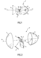
- Fig. 1 est une vue schématique en coupe verticale passant par l'axe optique d'un module optique à coupure selon l'invention.
- Fig. 2 est une vue schématique en perspective du module optique r de Fig. 1, alors que le miroir de renvoi est en position de travail.
- Fig. 3 est une coupe verticale schématique, semblable à Fig. 1 d'une variante de réalisation.
- Fig. 4 est un schéma de la grille d'éclairement rectangulaire théorique pour une fonction lampe de ville ou DRL.
- Fig. 5 est une représentation simplifiée de courbes isolux obtenues pour la fonction lampe de ville avec les modules optiques des Figs. 1 à 3.
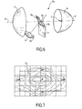
- Fig. 6 est une vue schématique en perspective, semblable à Fig. 2, d'un projecteur permettant d'assurer une fonction secondaire DRL, et
- Fig. 7 représente schématiquement les courbes isolux obtenues avec le module optique de Fig. 6.
- En se reportant à Figs. 1 et 2 des dessins, on peut voir un module optique lumineux P pour véhicule automobile prévu pour donner au moins un faisceau principal d'éclairage à coupure. Comme exemple de tel faisceau à coupure, on peut indiquer le faisceau code qui comprend, en général, une partie horizontale du côté où les véhicules se croisent, et une partie oblique montant du côté opposé, ou un faisceau antibrouillard à coupure horizontale.
- Le module optique P,représenté de manière schématique sans son boîtier, admet un axe optique X-X et comporte un réflecteur R de type elliptique avec un foyer intérieur Fi et un foyer extérieur Fe sur l'axe optique. Une source lumineuse principale S est placée au voisinage du foyer intérieur Fi ou à ce foyer.
- Un cache 1 est disposé dans le module optique sensiblement perpendiculairement à l'axe optique X-X. Le cache 1 présente un bord supérieur de coupure 2, situé au voisinage du foyer extérieur Fe. Dans l'exemple représenté sur Fig. 1 et Fig. 2, le faisceau principal d'éclairage est un faisceau code et le bord de coupure 2 (Fig. 2) comporte une partie horizontale 2a située d'un côté du plan vertical passant par l'axe optique et une partie inclinée vers le bas 2b située de l'autre côté de ce plan vertical.
- Une lentille convergente 3 est située en avant du cache et admet un plan focal B3 au voisinage du foyer extérieur Fe ou passant par ce foyer.
- Le sens de propagation de la lumière depuis la source S vers la lentille 3, de la droite vers la gauche selon Fig. 1, correspond au sens « avant ».
- Une source lumineuse secondaire 4 est disposée, selon la direction parallèle à l'axe optique, entre le cache 1 et la lentille 3 pour réaliser une fonction secondaire d'éclairage.
- Le module optique P comporte un miroir de renvoi 5 escamotable. Ce miroir 5 peut occuper une position escamotée représentée en tirets sur Fig. 1 dans laquelle il n'interfère pas avec le faisceau principal. Dans une position de travail, illustrée en trait plein sur Fig. 1 et sur Fig. 2, le miroir de renvoi 5 se trouve au voisinage du plan focal de la lentille, est centré sur l'axe optique X-X et est orienté de manière à donner, à partir du faisceau issu de la source secondaire 4, une grille d'éclairement G (Fig. 4) sensiblement rectangulaire centrée sur l'axe optique, correspondant à la fonction secondaire d'éclairage souhaitée.
- La forme de la grille G de Fig. 4 correspond à une fonction lampe de ville ou feu diurne (DRL). L'étendue en azimut est de +20° à -20° horizontalement de part et d'autre de l'axe optique et, en site, de -10° à +10° verticalement.
- Selon la réalisation de Figs. 1 et 2, le cache 1 est maintenu fixe dans le projecteur. Le miroir escamotable 5 est disposé en avant du cache 1 et est articulé autour d'un axe horizontal 6, orthogonal à l'axe optique X-X et situé en partie basse selon Fig.1. Des moyens de commande (non représentés) sont prévus pour faire passer le miroir 5 de la position effacée (en tirets) à la position en trait plein représentée sur Fig. 1.
- Le miroir de renvoi 5 est généralement un miroir plan, rectangulaire dont le grand côté est sensiblement horizontal, parallèle à l'axe d'articulation 6.
- La source secondaire 4 a son centre situé dans un plan vertical passant par l'axe optique X-X et est écartée transversalement de cet axe, vers le bas selon la réalisation des Figs. 1 et 2. Le miroir de renvoi 5, dans sa position de travail, est incliné vers la source secondaire 4 pour renvoyer le faisceau vers la lentille 3. De préférence, l'angle d'inclinaison du miroir 5 par rapport à l'axe optique est tel que l'image de la source secondaire 4 se trouve sur l'axe optique X-X ou au voisinage.
- Le miroir de renvoi 5 doit couvrir une ouverture angulaire, par rapport au point principal objet de la lentille 3, correspondant à la grandeur du faisceau. Il faut reproduire au foyer de la lentille la grandeur du faisceau à l'infini. Par exemple, pour obtenir la grille d'éclairement de Fig. 4, il faudra que le miroir 5, suivant la direction verticale, couvre de part et d'autre du plan horizontal une hauteur égale à :

- Le demi-côté horizontal du miroir est au moins égal à la distance focale multipliée par tangente 20°.
- La source lumineuse secondaire 4 est disposée de manière à ne pas interférer avec le faisceau principal lorsque la source S est allumée. Selon Figs. 1 et 2, la source 4 est située en partie basse et éclaire vers le haut en direction du miroir de renvoi 5.
- La lentille 3 forme une image angulaire du miroir de renvoi 5 éclairé par la source secondaire 4. Le faisceau secondaire créé est à l'image de la répartition de l'éclairement sur le miroir de renvoi 5 sous réserve que la lumière réfléchie par le miroir 5 soit recueillie par la lentille, ce pourquoi le miroir de renvoi 5 est incliné.
- Pour une fonction secondaire lampe de ville ou feu de position, on peut utiliser comme source secondaire 4 une lampe H6W. Les courbes isolux obtenues sont illustrées schématiquement sur Fig. 5. La courbe C1 correspond à un niveau de 8 cd (candelas) tandis que la courbe C2 sensiblement rectangulaire qui entoure l'axe optique correspond à un niveau de 3,6 cd. Ces intensités sont mesurées sur un écran situé à 10 m du projecteur comprenant le module optique selon l'invention, et orthogonal par rapport à l'axe optique.
- Le faisceau est limité sur les côtés par le bord de la lentille. On pourrait avoir un faisceau plus large en refermant le miroir de renvoi sur les bords pour converger sur la lentille 3.
- Le fonctionnement du module optique des Fig. 1 et 2 est le suivant.
- Lorsque la commande (non représentée) de ce module optique est placée dans une position correspondant à la production du faisceau principal d'éclairage à coupure, la source principale S est alimentée en courant électrique, la source secondaire 4 est éteinte et le miroir de renvoi 5 est dans la position escamotée représentée en tirets sur Fig.1. Le faisceau de lumière renvoyé par le réflecteur R, en provenant de la source S, est coupé par le bord supérieur 2 du cache 1.
- Sur un écran situé à distance de la lentille 3, l'éclairement sera assuré au-dessous d'une ligne de coupure correspondant à l'image du bord 2 donnée par la lentille 3.
- Lorsque la commande du module optique P occupe une position correspondant à la fonction secondaire d'éclairage, la source principale S est éteinte, la source secondaire 4 est allumée et le miroir de renvoi 5 passe dans la position représentée en trait plein sur Fig.1 sous l'action de moyens moteurs (non représentés) assurant sa rotation autour de l'axe 6.
- Le faisceau lumineux issu de la source 4 et tombant sur le miroir 5 est dirigé sur la lentille 3 qui donne une grille d'éclairage correspondant à l'image du miroir 5.
- Fig. 3 illustre une variante de réalisation selon laquelle le cache 1 a est monté mobile en translation verticale et le miroir de renvoi 5a est lié au cache 1 a. Par coulissement vertical, le cache 1 a peut venir dans la position active illustrée en tirets sur Fig. 3 tandis que le miroir de renvoi 5a est dans la position inactive également illustrée en tirets sur cette même figure.
- Par déplacement en translation vers le haut, le cache 1 a est placé dans une position inactive tandis que le miroir de renvoi 5a est placé dans la position de travail illustrée en trait plein qui passe exactement par le foyer de la lentille 3.
- En variante, le cache 1 pourrait être monté mobile en rotation autour d'un axe vertical, tandis que le miroir de renvoi serait décalé angulairement par rapport au cache tout en étant lié à ce cache dans le mouvement de rotation, de sorte que pour une première position angulaire, le cache serait en position active et le miroir de renvoi en position escamotée, tandis que dans une autre position angulaire, le cache serait en position inactive et le miroir de renvoi en position de travail.
- Le fonctionnement du module optique de Fig.3 est le suivant.
- Lorsque le conducteur commande la production du faisceau principal d'éclairage, la source principale S est allumée, la source secondaire 4 est éteinte et le cache 1 a est placé dans la position active représentée en tirets sur Fig.3 par des moyens de déplacement (non représentés) de sorte que le bord supérieur du cache 1 a se situe au voisinage du foyer de la lentille 3.
- Lorsque la fonction secondaire est commandée, la source S est éteinte tandis que la source 4 est allumée et les moyens de déplacement de l'ensemble : cache 1a et miroir de renvoi 5a provoquent une translation vers le haut, dans l'exemple de Fig.3. Le miroir de renvoi 5a vient occuper la position en trait plein, le centre du miroir étant situé sur l'axe optique X-X. Le faisceau lumineux provenant de la source 4 est renvoyé par le miroir 5a sur la lentille 3 ce qui permet d'obtenir une grille d'éclairement rectangulaire sensiblement centrée sur l'axe optique.
- En se reportant à Fig.6, on peut voir un module optique Pb, selon l'invention, qui permet d'obtenir un faisceau principal d'éclairage à coupure et une fonction secondaire d'éclairage du type feu diurne ou DRL nécessitant un flux lumineux plus important que la lampe ville.
- La source secondaire 4b est orientée de manière à éclairer à l'opposé du miroir de renvoi 5b. L'escamotage du miroir 5b peut être réalisé selon l'une des manières exposées précédemment. Sur Fig.6, le miroir de renvoi 5b est représenté dans sa position de travail.
- La source secondaire 4b éclaire un miroir récupérateur 7 concave fixe qui réfléchit la lumière en la concentrant vers le miroir de renvoi 5b : on obtient une efficacité accrue nécessaire pour la fonction DRL, la lumière pouvant être refocalisée vers le centre du miroir 5b : on peut obtenir en sortie de lentille un faisceau lumineux plus intense.
- Les niveaux d'éclairement demandés pour un feu diurne ou DRL sont de l'ordre de 100 fois supérieurs à ceux demandés pour une lampe ville. La source lumineuse 4b est choisie d'une puissance supérieure à celle retenue pour la fonction lampe ville. A titre d'exemple non limitatif, la source 4b peut être constituée par une lampe H21 donnant un flux d'environ 600 lumens lorsqu'elle est alimentée sous la tension nominale.
- Le miroir récupérateur 7 est généralement du type parabolique et peut comporter des facettes qui créent la répartition de lumière souhaitée sur le miroir de renvoi 5b.
- Dans les exemples représentés, la source secondaire 4 ou 4b est située dans le plan vertical passant par l'axe optique, au-dessous de cet axe optique. En variante, la source secondaire pourrait être située sur le côté, par exemple dans le plan horizontal passant par l'axe optique à droite ou à gauche de cet axe, auquel cas le miroir de renvoi 5, 5b devrait être tourné de manière appropriée par rapport à la verticale passant par son centre pour assurer l'éclairement correct de la lentille 3.
- L'exemple fourni avec source 4b éclairant à l'opposé du miroir de renvoi 5b vers un miroir récupérateur 7 n'est pas limitatif. Dans le cas d'une source secondaire de puissance suffisante, le miroir de renvoi 5b pourrait être éclairé directement par cette source secondaire pour assurer la fonction DRL . Le cas échéant, une lentille de Fresnel pourrait être disposée entre la source secondaire éclairant en direction du miroir de renvoi 5b et ce miroir.
- On pourrait utiliser comme source secondaire au moins une diode électroluminescente (led), sous réserve que cette diode puisse supporter la température régnant à l'intérieur du projecteur elliptique, notamment lorsque la fonction principale est réalisée.
- Fig.7 représente les courbes isolux obtenues sur un écran avec le module optique de Fig.6. Ces courbes sont sensiblement centrées sur le point O intersection de l'axe optique avec l'écran vertical. La courbe C4 montre que l'éclairement est assuré dans une plage sensiblement rectangulaire de ± 10° en site et de ± 20°en azimut. La grille DRL ou feu diurne est semblable, pour la forme, à celle de la lampe ville, seuls les niveaux d'éclairement étant différents.
- Il est possible de réaliser, en plus de la fonction DRL, une fonction secondaire lampe ville en alimentant la source secondaire 4b sous une tension inférieure à la tension nominale. Le sous voltage de la lampe 4b est choisi de manière que le flux de cette lampe corresponde à celui souhaité pour une lampe ville. Le module optique de Fig.6 permet alors d'assurer trois fonctions à savoir : une fonction principale avec faisceau à coupure, et deux fonctions secondaires respectivement DRL et lampe ville.
- Pour la fonction principale, le miroir de renvoi 5b est placé dans une position escamotée dégageant totalement le bord de coupure supérieur du cache, tandis que la source secondaire 4b est éteinte. Pour la réalisation des fonctions secondaires, le miroir de renvoi 5b est placé en position de travail, la source principale S est éteinte et la source secondaire 4b est allumée en étant alimentée soit sous sa tension nominale (feu DRL) soit en étant sous voltée (lampe ville).
Claims (15)
- Module optique destiné à équiper des dispositifs d'éclairage automobile du type projecteur, prévu pour donner au moins un faisceau principal d'éclairage à coupure et admettant un axe optique, comportant :- un réflecteur de type elliptique (R) ayant un foyer intérieur (Fi) et un foyer extérieur sur l'axe optique (X-X) ;- une source lumineuse principale (S) disposée au voisinage du foyer intérieur (Fi) ;- un cache (1) présentant un bord de coupure au voisinage du foyer extérieur (Fe),- une optique, en particulier une lentille (3) convergente, située en avant du cache (1) et admettant un plan focal au voisinage du foyer extérieur (Fe),- et une source lumineuse secondaire (4), disposée entre le cache et l'optique, permettant de réaliser une fonction secondaire d'éclairage,caractérisé en ce qu'il comporte un miroir de renvoi escamotable (5, 5a, 5b) pouvant passer d'une position escamotée, où le miroir n'interfère substantiellement pas avec le faisceau principal, à une position de travail dans laquelle ledit miroir de renvoi se trouve au voisinage du plan focal (B3) de la lentille (3), substantiellement centré sur l'axe optique (X-X) et orienté de manière à donner, à partir des rayons lumineux issus de la source secondaire (4,4b), un faisceau secondaire substantiellement centré sur l'axe optique(X-X) et constituant la fonction secondaire d'éclairage.
- Module selon la revendication précédente, caractérisé en ce que le faisceau secondaire est conforme à une grille d'éclairement sensiblement rectangulaire.
- Module optique selon l'une des revendications précédentes, caractérisé en ce que le miroir de renvoi (5,5a,5b) est substantiellement plan, de préférence rectangulaire.
- Module optique selon l'une des revendications précédentes, caractérisé en ce que le cache (1) est fixe et le miroir de renvoi (5), dans sa position de travail, se trouve en avant du cache.
- Module optique selon l'une des revendications 1 à 3, caractérisé en ce que le cache (1a) est monté mobile, notamment en translation ou en rotation, et est effacé pour permettre la mise en place du miroir de renvoi (5a) en position de travail.
- Module optique selon l'une des revendications précédentes, caractérisé en ce que la source secondaire (4,4b) est située dans le plan vertical passant par l'axe optique (X-X) et est écartée transversalement de cet axe, et le miroir de renvoi (5,5a,5b), dans sa position de travail, est incliné vers la source secondaire par rapport à l'axe optique.
- Module optique selon la revendication 6, caractérisé en ce que l'angle d'inclinaison du miroir de renvoi (5,5a,5b) est tel que l'image de la source secondaire (4,4b) donnée par le miroir de renvoi est dirigé vers la lentille (3).
- Module optique selon l'une des revendications précédentes, caractérisé en ce que le centre du miroir de renvoi (5,5a,5b) se trouve au voisinage du foyer de la lentille (3).
- Module optique selon l'une des revendications précédentes, caractérisé en ce que la source secondaire (4) est orientée de manière à éclairer directement le miroir de renvoi (5,5a).
- Module optique selon l'une des revendications précédentes, caractérisé en ce que la source secondaire (4) a une alimentation électrique variable.
- Module optique selon l'une des revendications 1 à 8, caractérisé en ce que la source secondaire (4b) est orientée de manière à éclairer à l'opposé du miroir de renvoi (5b), vers un miroir récupérateur concave fixe (7) qui réfléchit et concentre la lumière sur le miroir de renvoi.
- Module optique selon l'une quelconque des revendications précédentes, caractérisé en ce qu'il est apte à émettre au moins un faisceau principal à coupure, notamment choisi parmi les faisceaux code et antibrouillard.
- Module optique selon la revendication précédente, caractérisé en ce qu'il est apte à émettre un autre faisceau principal avec ou sans coupure, notamment de type faisceau route.
- Module optique selon l'une quelconque des revendications précédentes, caractérisé en ce que la fonction secondaire est une fonction lampe ville et/ou DRL
- Projecteur automobile comprenant un module optique selon l'une des revendications précédentes.
Applications Claiming Priority (1)
| Application Number | Priority Date | Filing Date | Title |
|---|---|---|---|
| FR0500669A FR2881207B1 (fr) | 2005-01-21 | 2005-01-21 | Module optique pour dispositif d'eclairage pour vehicule automobile, prevu pour donner au moins un faisceau principal a coupure |
Publications (2)
| Publication Number | Publication Date |
|---|---|
| EP1684004A1 true EP1684004A1 (fr) | 2006-07-26 |
| EP1684004B1 EP1684004B1 (fr) | 2008-06-11 |
Family
ID=34953261
Family Applications (1)
| Application Number | Title | Priority Date | Filing Date |
|---|---|---|---|
| EP06290112A Expired - Lifetime EP1684004B1 (fr) | 2005-01-21 | 2006-01-17 | Projecteur de véhicule automobile avec deux faisceaux d'éclairage |
Country Status (7)
| Country | Link |
|---|---|
| US (1) | US7201504B2 (fr) |
| EP (1) | EP1684004B1 (fr) |
| JP (1) | JP4711836B2 (fr) |
| AT (1) | ATE398263T1 (fr) |
| DE (1) | DE602006001403D1 (fr) |
| ES (1) | ES2308686T3 (fr) |
| FR (1) | FR2881207B1 (fr) |
Cited By (5)
| Publication number | Priority date | Publication date | Assignee | Title |
|---|---|---|---|---|
| WO2007124837A1 (fr) * | 2006-04-26 | 2007-11-08 | Bayerische Motoren Werke Aktiengesellschaft | Projecteur de véhicule à moteur |
| FR2923579A1 (fr) | 2007-11-13 | 2009-05-15 | Peugeot Citroen Automobiles Sa | Projecteur d'eclairage de vehicule automobile, a module elliptique. |
| EP2085685A1 (fr) | 2008-01-31 | 2009-08-05 | Peugeot Citroen Automobiles SA | Projecteur d'eclairage, notamment a module elliptique, pour vehicule automobile, a recuperation d'energie |
| FR2977001A1 (fr) * | 2011-06-21 | 2012-12-28 | Peugeot Citroen Automobiles Sa | Dispositif d'occultation a fonction(s) d'eclairage, pour un bloc optique de vehicule |
| EP2597357A1 (fr) * | 2011-11-24 | 2013-05-29 | Valeo Vision | Elément opaque et mobile empechant une focalisation des rayons solaires dans un projecteur |
Families Citing this family (6)
| Publication number | Priority date | Publication date | Assignee | Title |
|---|---|---|---|---|
| JP5152571B2 (ja) * | 2008-03-24 | 2013-02-27 | スタンレー電気株式会社 | 車両前照灯 |
| US8070338B2 (en) * | 2008-04-07 | 2011-12-06 | General Electric Company | Three-mode integrated headlamp |
| WO2012005685A1 (fr) * | 2010-07-05 | 2012-01-12 | I3 Lab Pte Ltd | Phare à del intégré |
| US8905609B2 (en) * | 2010-09-30 | 2014-12-09 | Osram Sylvania Inc. | Lighting system with shutter, reflector, primary light engine and a secondary light engine coupled to shutter |
| AT512569B1 (de) * | 2012-03-07 | 2014-09-15 | Zizala Lichtsysteme Gmbh | Beleuchtungsvorrichtung für ein Kraftfahrzeug |
| JP7053370B2 (ja) * | 2018-05-18 | 2022-04-12 | トヨタ自動車株式会社 | 車両用前照灯装置 |
Citations (8)
| Publication number | Priority date | Publication date | Assignee | Title |
|---|---|---|---|---|
| US2228476A (en) * | 1939-11-15 | 1941-01-14 | I P Whitaker | Headlight glare eliminator |
| FR2769688A1 (fr) * | 1997-10-14 | 1999-04-16 | Valeo Vision | Projecteur elliptique a coupure attenuee |
| DE10030362A1 (de) * | 2000-06-21 | 2002-01-03 | Volkswagen Ag | Fahrzeugscheinwerfer |
| EP1197387A1 (fr) | 2000-10-12 | 2002-04-17 | Valeo Vision | Projecteur pour véhicule automobile à écran d'occultation mobile |
| JP2003242811A (ja) * | 2002-02-15 | 2003-08-29 | Stanley Electric Co Ltd | 車幅灯兼用前照灯 |
| FR2840389A1 (fr) | 2002-06-04 | 2003-12-05 | Valeo Vision | Projecteur d'eclairage elliptique comportant une source lumineuse secondaire |
| WO2004085917A1 (fr) * | 2003-03-26 | 2004-10-07 | Daimlerchrysler Ag | Phare a eclairage indirect |
| FR2871552A1 (fr) | 2004-06-09 | 2005-12-16 | Valeo Vision Sa | Dispositif projecteur multifonctions de type elliptique |
Family Cites Families (11)
| Publication number | Priority date | Publication date | Assignee | Title |
|---|---|---|---|---|
| US3223246A (en) * | 1964-06-22 | 1965-12-14 | Maurice L Daitch | Shelving apparatus and installation thereof between wall studs |
| US5264993A (en) * | 1990-01-30 | 1993-11-23 | Robert Bosch Gmbh | Headlamp for power vehicles |
| JP3967048B2 (ja) * | 1999-10-05 | 2007-08-29 | 株式会社小糸製作所 | 車両用前照灯 |
| JP4015340B2 (ja) * | 2000-02-21 | 2007-11-28 | 株式会社小糸製作所 | 車両用前照灯 |
| JP2002093217A (ja) * | 2000-09-19 | 2002-03-29 | Stanley Electric Co Ltd | 車両用灯具 |
| FR2826431B1 (fr) * | 2001-06-26 | 2004-04-16 | Valeo Vision | Dispositif d'eclairage ou de signalisation pour vehicule automobile |
| FR2827945B1 (fr) * | 2001-07-26 | 2004-02-27 | Valeo Vision | Projecteur elliptique equipe de caches a axes de pivotement transversaux pour vehicule automobile |
| FR2830073B1 (fr) * | 2001-09-27 | 2003-12-12 | Valeo Vision | Projecteur d'eclairage elliptique de vehicule automobile comportant un systeme optique secondaire |
| JP2004051080A (ja) * | 2002-05-31 | 2004-02-19 | Mikku Works Kk | 車両用昼間点灯装置 |
| JP4040955B2 (ja) * | 2002-11-06 | 2008-01-30 | 株式会社小糸製作所 | 車両用前照灯及びその製造方法 |
| JP3911241B2 (ja) * | 2003-01-23 | 2007-05-09 | 株式会社小糸製作所 | 車輌用前照灯 |
-
2005
- 2005-01-21 FR FR0500669A patent/FR2881207B1/fr not_active Expired - Fee Related
-
2006
- 2006-01-17 ES ES06290112T patent/ES2308686T3/es not_active Expired - Lifetime
- 2006-01-17 EP EP06290112A patent/EP1684004B1/fr not_active Expired - Lifetime
- 2006-01-17 AT AT06290112T patent/ATE398263T1/de not_active IP Right Cessation
- 2006-01-17 DE DE602006001403T patent/DE602006001403D1/de not_active Expired - Lifetime
- 2006-01-20 US US11/336,542 patent/US7201504B2/en not_active Expired - Fee Related
- 2006-01-20 JP JP2006011901A patent/JP4711836B2/ja not_active Expired - Fee Related
Patent Citations (8)
| Publication number | Priority date | Publication date | Assignee | Title |
|---|---|---|---|---|
| US2228476A (en) * | 1939-11-15 | 1941-01-14 | I P Whitaker | Headlight glare eliminator |
| FR2769688A1 (fr) * | 1997-10-14 | 1999-04-16 | Valeo Vision | Projecteur elliptique a coupure attenuee |
| DE10030362A1 (de) * | 2000-06-21 | 2002-01-03 | Volkswagen Ag | Fahrzeugscheinwerfer |
| EP1197387A1 (fr) | 2000-10-12 | 2002-04-17 | Valeo Vision | Projecteur pour véhicule automobile à écran d'occultation mobile |
| JP2003242811A (ja) * | 2002-02-15 | 2003-08-29 | Stanley Electric Co Ltd | 車幅灯兼用前照灯 |
| FR2840389A1 (fr) | 2002-06-04 | 2003-12-05 | Valeo Vision | Projecteur d'eclairage elliptique comportant une source lumineuse secondaire |
| WO2004085917A1 (fr) * | 2003-03-26 | 2004-10-07 | Daimlerchrysler Ag | Phare a eclairage indirect |
| FR2871552A1 (fr) | 2004-06-09 | 2005-12-16 | Valeo Vision Sa | Dispositif projecteur multifonctions de type elliptique |
Non-Patent Citations (1)
| Title |
|---|
| PATENT ABSTRACTS OF JAPAN vol. 2003, no. 12 5 December 2003 (2003-12-05) * |
Cited By (7)
| Publication number | Priority date | Publication date | Assignee | Title |
|---|---|---|---|---|
| WO2007124837A1 (fr) * | 2006-04-26 | 2007-11-08 | Bayerische Motoren Werke Aktiengesellschaft | Projecteur de véhicule à moteur |
| FR2923579A1 (fr) | 2007-11-13 | 2009-05-15 | Peugeot Citroen Automobiles Sa | Projecteur d'eclairage de vehicule automobile, a module elliptique. |
| EP2085685A1 (fr) | 2008-01-31 | 2009-08-05 | Peugeot Citroen Automobiles SA | Projecteur d'eclairage, notamment a module elliptique, pour vehicule automobile, a recuperation d'energie |
| FR2977001A1 (fr) * | 2011-06-21 | 2012-12-28 | Peugeot Citroen Automobiles Sa | Dispositif d'occultation a fonction(s) d'eclairage, pour un bloc optique de vehicule |
| EP2597357A1 (fr) * | 2011-11-24 | 2013-05-29 | Valeo Vision | Elément opaque et mobile empechant une focalisation des rayons solaires dans un projecteur |
| FR2983279A1 (fr) * | 2011-11-24 | 2013-05-31 | Valeo Vision | Element opaque et mobile empechant une focalisation des rayons solaires dans un projecteur |
| US9033560B2 (en) | 2011-11-24 | 2015-05-19 | Valeo Vision | Opaque and movable element preventing solar rays from focusing in a headlamp |
Also Published As
| Publication number | Publication date |
|---|---|
| FR2881207B1 (fr) | 2007-08-17 |
| JP4711836B2 (ja) | 2011-06-29 |
| US7201504B2 (en) | 2007-04-10 |
| JP2006202754A (ja) | 2006-08-03 |
| ATE398263T1 (de) | 2008-07-15 |
| DE602006001403D1 (de) | 2008-07-24 |
| EP1684004B1 (fr) | 2008-06-11 |
| US20060164851A1 (en) | 2006-07-27 |
| FR2881207A1 (fr) | 2006-07-28 |
| ES2308686T3 (es) | 2008-12-01 |
Similar Documents
| Publication | Publication Date | Title |
|---|---|---|
| EP3002504B1 (fr) | Module lumineux pour l'éclairage d'un véhicule automobile | |
| EP2006605B1 (fr) | Module optique pour dispositif d'éclairage automobile | |
| FR2923285A1 (fr) | Phare de vehicule. | |
| EP1308669A1 (fr) | Dispositif d'éclairage de type elliptique pour véhicule automobile | |
| EP3372893A1 (fr) | Elément optique primaire, module lumineux et projecteur pour véhicule automobile | |
| FR2809358A1 (fr) | Phare de vehicule ayant deux unites a lampe | |
| FR2787863A1 (fr) | Installation de projecteurs pour vehicules generant des faisceaux lumineux a caracteristiques differentes | |
| EP2799286B1 (fr) | Module d'éclairage et/ou de signalisation rotatif et multifonctions | |
| EP1686310B1 (fr) | Projecteur verticalisé pour véhicule automobile | |
| EP3115683B1 (fr) | Dispositif d'eclairage d'un vehicule automobile | |
| EP1431654A1 (fr) | Projecteur de véhicule automobile assurant au moins deux fonctions | |
| EP2261556A1 (fr) | Dispositifs d'éclairage, notamment à diodes électroluminescentes, aptes à générer un faisceau lumineux adaptatif | |
| FR2888916A1 (fr) | Module optique pour dispositif d'eclairage automobile | |
| EP1684004B1 (fr) | Projecteur de véhicule automobile avec deux faisceaux d'éclairage | |
| EP1701087A2 (fr) | Projecteur à plusieurs fonctions pour véhicule automobile | |
| FR3002022A1 (fr) | Dispositif d'eclairage et/ou de signalisation a lentille torique | |
| EP1600689B1 (fr) | Projecteur lumineux multifonction pour véhicule automobile | |
| FR3038695A1 (fr) | Module lumineux pour l'eclairage et/ou la signalisation d'un vehicule automobile | |
| EP1944542B1 (fr) | Projecteur lumineux de type bifonction pour véhicule automobile | |
| WO1999011969A1 (fr) | Projecteur pour vehicule automobile, susceptible d'emettre des faisceaux differents | |
| EP1806531B1 (fr) | Dispositif projecteur elliptique multifonctions avec élément optique additionnel | |
| FR2966221A1 (fr) | Module d'eclairage a coupure avec reflecteur parabolique dispose sur un reflecteur elliptique | |
| FR2861832A1 (fr) | Projecteur pour vehicule automobile comportant une source lumineuse formee par une lampe a decharge | |
| FR2895778A1 (fr) | Phare a module elliptique pour vehicule automobile | |
| FR2856134A1 (fr) | Projecteur de vehicule automobile permettant d'assurer au moins deux fonctions. |
Legal Events
| Date | Code | Title | Description |
|---|---|---|---|
| PUAI | Public reference made under article 153(3) epc to a published international application that has entered the european phase |
Free format text: ORIGINAL CODE: 0009012 |
|
| AK | Designated contracting states |
Kind code of ref document: A1 Designated state(s): AT BE BG CH CY CZ DE DK EE ES FI FR GB GR HU IE IS IT LI LT LU LV MC NL PL PT RO SE SI SK TR |
|
| AX | Request for extension of the european patent |
Extension state: AL BA HR MK YU |
|
| 17P | Request for examination filed |
Effective date: 20061213 |
|
| 17Q | First examination report despatched |
Effective date: 20070116 |
|
| AKX | Designation fees paid |
Designated state(s): AT BE BG CH CY CZ DE DK EE ES FI FR GB GR HU IE IS IT LI LT LU LV MC NL PL PT RO SE SI SK TR |
|
| GRAP | Despatch of communication of intention to grant a patent |
Free format text: ORIGINAL CODE: EPIDOSNIGR1 |
|
| GRAS | Grant fee paid |
Free format text: ORIGINAL CODE: EPIDOSNIGR3 |
|
| GRAA | (expected) grant |
Free format text: ORIGINAL CODE: 0009210 |
|
| AK | Designated contracting states |
Kind code of ref document: B1 Designated state(s): AT BE BG CH CY CZ DE DK EE ES FI FR GB GR HU IE IS IT LI LT LU LV MC NL PL PT RO SE SI SK TR |
|
| REG | Reference to a national code |
Ref country code: GB Ref legal event code: FG4D Free format text: NOT ENGLISH |
|
| REG | Reference to a national code |
Ref country code: CH Ref legal event code: EP |
|
| REF | Corresponds to: |
Ref document number: 602006001403 Country of ref document: DE Date of ref document: 20080724 Kind code of ref document: P |
|
| REG | Reference to a national code |
Ref country code: IE Ref legal event code: FG4D Free format text: LANGUAGE OF EP DOCUMENT: FRENCH |
|
| PG25 | Lapsed in a contracting state [announced via postgrant information from national office to epo] |
Ref country code: SI Free format text: LAPSE BECAUSE OF FAILURE TO SUBMIT A TRANSLATION OF THE DESCRIPTION OR TO PAY THE FEE WITHIN THE PRESCRIBED TIME-LIMIT Effective date: 20080611 Ref country code: FI Free format text: LAPSE BECAUSE OF FAILURE TO SUBMIT A TRANSLATION OF THE DESCRIPTION OR TO PAY THE FEE WITHIN THE PRESCRIBED TIME-LIMIT Effective date: 20080611 |
|
| PG25 | Lapsed in a contracting state [announced via postgrant information from national office to epo] |
Ref country code: LV Free format text: LAPSE BECAUSE OF FAILURE TO SUBMIT A TRANSLATION OF THE DESCRIPTION OR TO PAY THE FEE WITHIN THE PRESCRIBED TIME-LIMIT Effective date: 20080611 Ref country code: PL Free format text: LAPSE BECAUSE OF FAILURE TO SUBMIT A TRANSLATION OF THE DESCRIPTION OR TO PAY THE FEE WITHIN THE PRESCRIBED TIME-LIMIT Effective date: 20080611 Ref country code: NL Free format text: LAPSE BECAUSE OF FAILURE TO SUBMIT A TRANSLATION OF THE DESCRIPTION OR TO PAY THE FEE WITHIN THE PRESCRIBED TIME-LIMIT Effective date: 20080611 Ref country code: AT Free format text: LAPSE BECAUSE OF FAILURE TO SUBMIT A TRANSLATION OF THE DESCRIPTION OR TO PAY THE FEE WITHIN THE PRESCRIBED TIME-LIMIT Effective date: 20080611 |
|
| NLV1 | Nl: lapsed or annulled due to failure to fulfill the requirements of art. 29p and 29m of the patents act | ||
| REG | Reference to a national code |
Ref country code: ES Ref legal event code: FG2A Ref document number: 2308686 Country of ref document: ES Kind code of ref document: T3 |
|
| PG25 | Lapsed in a contracting state [announced via postgrant information from national office to epo] |
Ref country code: SE Free format text: LAPSE BECAUSE OF FAILURE TO SUBMIT A TRANSLATION OF THE DESCRIPTION OR TO PAY THE FEE WITHIN THE PRESCRIBED TIME-LIMIT Effective date: 20080911 Ref country code: CZ Free format text: LAPSE BECAUSE OF FAILURE TO SUBMIT A TRANSLATION OF THE DESCRIPTION OR TO PAY THE FEE WITHIN THE PRESCRIBED TIME-LIMIT Effective date: 20080611 Ref country code: LT Free format text: LAPSE BECAUSE OF FAILURE TO SUBMIT A TRANSLATION OF THE DESCRIPTION OR TO PAY THE FEE WITHIN THE PRESCRIBED TIME-LIMIT Effective date: 20080611 Ref country code: IS Free format text: LAPSE BECAUSE OF FAILURE TO SUBMIT A TRANSLATION OF THE DESCRIPTION OR TO PAY THE FEE WITHIN THE PRESCRIBED TIME-LIMIT Effective date: 20081011 |
|
| PG25 | Lapsed in a contracting state [announced via postgrant information from national office to epo] |
Ref country code: SK Free format text: LAPSE BECAUSE OF FAILURE TO SUBMIT A TRANSLATION OF THE DESCRIPTION OR TO PAY THE FEE WITHIN THE PRESCRIBED TIME-LIMIT Effective date: 20080611 Ref country code: RO Free format text: LAPSE BECAUSE OF FAILURE TO SUBMIT A TRANSLATION OF THE DESCRIPTION OR TO PAY THE FEE WITHIN THE PRESCRIBED TIME-LIMIT Effective date: 20080611 Ref country code: PT Free format text: LAPSE BECAUSE OF FAILURE TO SUBMIT A TRANSLATION OF THE DESCRIPTION OR TO PAY THE FEE WITHIN THE PRESCRIBED TIME-LIMIT Effective date: 20081111 |
|
| REG | Reference to a national code |
Ref country code: IE Ref legal event code: FD4D |
|
| PLBE | No opposition filed within time limit |
Free format text: ORIGINAL CODE: 0009261 |
|
| STAA | Information on the status of an ep patent application or granted ep patent |
Free format text: STATUS: NO OPPOSITION FILED WITHIN TIME LIMIT |
|
| PG25 | Lapsed in a contracting state [announced via postgrant information from national office to epo] |
Ref country code: IE Free format text: LAPSE BECAUSE OF FAILURE TO SUBMIT A TRANSLATION OF THE DESCRIPTION OR TO PAY THE FEE WITHIN THE PRESCRIBED TIME-LIMIT Effective date: 20080611 Ref country code: EE Free format text: LAPSE BECAUSE OF FAILURE TO SUBMIT A TRANSLATION OF THE DESCRIPTION OR TO PAY THE FEE WITHIN THE PRESCRIBED TIME-LIMIT Effective date: 20080611 Ref country code: BG Free format text: LAPSE BECAUSE OF FAILURE TO SUBMIT A TRANSLATION OF THE DESCRIPTION OR TO PAY THE FEE WITHIN THE PRESCRIBED TIME-LIMIT Effective date: 20080911 Ref country code: DK Free format text: LAPSE BECAUSE OF FAILURE TO SUBMIT A TRANSLATION OF THE DESCRIPTION OR TO PAY THE FEE WITHIN THE PRESCRIBED TIME-LIMIT Effective date: 20080611 |
|
| 26N | No opposition filed |
Effective date: 20090312 |
|
| PG25 | Lapsed in a contracting state [announced via postgrant information from national office to epo] |
Ref country code: MC Free format text: LAPSE BECAUSE OF NON-PAYMENT OF DUE FEES Effective date: 20090131 |
|
| PG25 | Lapsed in a contracting state [announced via postgrant information from national office to epo] |
Ref country code: BE Free format text: LAPSE BECAUSE OF NON-PAYMENT OF DUE FEES Effective date: 20090131 |
|
| REG | Reference to a national code |
Ref country code: CH Ref legal event code: PL |
|
| GBPC | Gb: european patent ceased through non-payment of renewal fee |
Effective date: 20100117 |
|
| PG25 | Lapsed in a contracting state [announced via postgrant information from national office to epo] |
Ref country code: LI Free format text: LAPSE BECAUSE OF NON-PAYMENT OF DUE FEES Effective date: 20100131 Ref country code: CH Free format text: LAPSE BECAUSE OF NON-PAYMENT OF DUE FEES Effective date: 20100131 Ref country code: GR Free format text: LAPSE BECAUSE OF FAILURE TO SUBMIT A TRANSLATION OF THE DESCRIPTION OR TO PAY THE FEE WITHIN THE PRESCRIBED TIME-LIMIT Effective date: 20080912 |
|
| PG25 | Lapsed in a contracting state [announced via postgrant information from national office to epo] |
Ref country code: GB Free format text: LAPSE BECAUSE OF NON-PAYMENT OF DUE FEES Effective date: 20100117 |
|
| PG25 | Lapsed in a contracting state [announced via postgrant information from national office to epo] |
Ref country code: LU Free format text: LAPSE BECAUSE OF NON-PAYMENT OF DUE FEES Effective date: 20090117 |
|
| PG25 | Lapsed in a contracting state [announced via postgrant information from national office to epo] |
Ref country code: HU Free format text: LAPSE BECAUSE OF FAILURE TO SUBMIT A TRANSLATION OF THE DESCRIPTION OR TO PAY THE FEE WITHIN THE PRESCRIBED TIME-LIMIT Effective date: 20081212 |
|
| PG25 | Lapsed in a contracting state [announced via postgrant information from national office to epo] |
Ref country code: TR Free format text: LAPSE BECAUSE OF FAILURE TO SUBMIT A TRANSLATION OF THE DESCRIPTION OR TO PAY THE FEE WITHIN THE PRESCRIBED TIME-LIMIT Effective date: 20080611 |
|
| PG25 | Lapsed in a contracting state [announced via postgrant information from national office to epo] |
Ref country code: CY Free format text: LAPSE BECAUSE OF FAILURE TO SUBMIT A TRANSLATION OF THE DESCRIPTION OR TO PAY THE FEE WITHIN THE PRESCRIBED TIME-LIMIT Effective date: 20080611 |
|
| PGFP | Annual fee paid to national office [announced via postgrant information from national office to epo] |
Ref country code: IT Payment date: 20120124 Year of fee payment: 7 |
|
| PGFP | Annual fee paid to national office [announced via postgrant information from national office to epo] |
Ref country code: DE Payment date: 20130110 Year of fee payment: 8 Ref country code: ES Payment date: 20130121 Year of fee payment: 8 Ref country code: FR Payment date: 20130225 Year of fee payment: 8 |
|
| REG | Reference to a national code |
Ref country code: DE Ref legal event code: R119 Ref document number: 602006001403 Country of ref document: DE |
|
| PG25 | Lapsed in a contracting state [announced via postgrant information from national office to epo] |
Ref country code: DE Free format text: LAPSE BECAUSE OF NON-PAYMENT OF DUE FEES Effective date: 20140801 |
|
| REG | Reference to a national code |
Ref country code: FR Ref legal event code: ST Effective date: 20140930 |
|
| REG | Reference to a national code |
Ref country code: DE Ref legal event code: R119 Ref document number: 602006001403 Country of ref document: DE Effective date: 20140801 |
|
| PG25 | Lapsed in a contracting state [announced via postgrant information from national office to epo] |
Ref country code: FR Free format text: LAPSE BECAUSE OF NON-PAYMENT OF DUE FEES Effective date: 20140131 |
|
| REG | Reference to a national code |
Ref country code: ES Ref legal event code: FD2A Effective date: 20150327 |
|
| PG25 | Lapsed in a contracting state [announced via postgrant information from national office to epo] |
Ref country code: ES Free format text: LAPSE BECAUSE OF NON-PAYMENT OF DUE FEES Effective date: 20140118 |
|
| PG25 | Lapsed in a contracting state [announced via postgrant information from national office to epo] |
Ref country code: IT Free format text: LAPSE BECAUSE OF NON-PAYMENT OF DUE FEES Effective date: 20140117 |