EP1683672A2 - Fuel-effusion prevention valve - Google Patents
Fuel-effusion prevention valve Download PDFInfo
- Publication number
- EP1683672A2 EP1683672A2 EP20060001148 EP06001148A EP1683672A2 EP 1683672 A2 EP1683672 A2 EP 1683672A2 EP 20060001148 EP20060001148 EP 20060001148 EP 06001148 A EP06001148 A EP 06001148A EP 1683672 A2 EP1683672 A2 EP 1683672A2
- Authority
- EP
- European Patent Office
- Prior art keywords
- fuel
- float
- case
- prevention valve
- effusion prevention
- Prior art date
- Legal status (The legal status is an assumption and is not a legal conclusion. Google has not performed a legal analysis and makes no representation as to the accuracy of the status listed.)
- Withdrawn
Links
Images


Classifications
-
- F—MECHANICAL ENGINEERING; LIGHTING; HEATING; WEAPONS; BLASTING
- F16—ENGINEERING ELEMENTS AND UNITS; GENERAL MEASURES FOR PRODUCING AND MAINTAINING EFFECTIVE FUNCTIONING OF MACHINES OR INSTALLATIONS; THERMAL INSULATION IN GENERAL
- F16K—VALVES; TAPS; COCKS; ACTUATING-FLOATS; DEVICES FOR VENTING OR AERATING
- F16K24/00—Devices, e.g. valves, for venting or aerating enclosures
- F16K24/04—Devices, e.g. valves, for venting or aerating enclosures for venting only
- F16K24/042—Devices, e.g. valves, for venting or aerating enclosures for venting only actuated by a float
- F16K24/044—Devices, e.g. valves, for venting or aerating enclosures for venting only actuated by a float the float being rigidly connected to the valve element, the assembly of float and valve element following a substantially translational movement when actuated, e.g. also for actuating a pilot valve
-
- B—PERFORMING OPERATIONS; TRANSPORTING
- B60—VEHICLES IN GENERAL
- B60K—ARRANGEMENT OR MOUNTING OF PROPULSION UNITS OR OF TRANSMISSIONS IN VEHICLES; ARRANGEMENT OR MOUNTING OF PLURAL DIVERSE PRIME-MOVERS IN VEHICLES; AUXILIARY DRIVES FOR VEHICLES; INSTRUMENTATION OR DASHBOARDS FOR VEHICLES; ARRANGEMENTS IN CONNECTION WITH COOLING, AIR INTAKE, GAS EXHAUST OR FUEL SUPPLY OF PROPULSION UNITS IN VEHICLES
- B60K15/00—Arrangement in connection with fuel supply of combustion engines or other fuel consuming energy converters, e.g. fuel cells; Mounting or construction of fuel tanks
- B60K15/03—Fuel tanks
- B60K15/035—Fuel tanks characterised by venting means
- B60K15/03519—Valve arrangements in the vent line
-
- Y—GENERAL TAGGING OF NEW TECHNOLOGICAL DEVELOPMENTS; GENERAL TAGGING OF CROSS-SECTIONAL TECHNOLOGIES SPANNING OVER SEVERAL SECTIONS OF THE IPC; TECHNICAL SUBJECTS COVERED BY FORMER USPC CROSS-REFERENCE ART COLLECTIONS [XRACs] AND DIGESTS
- Y10—TECHNICAL SUBJECTS COVERED BY FORMER USPC
- Y10T—TECHNICAL SUBJECTS COVERED BY FORMER US CLASSIFICATION
- Y10T137/00—Fluid handling
- Y10T137/2931—Diverse fluid containing pressure systems
- Y10T137/3003—Fluid separating traps or vents
- Y10T137/3084—Discriminating outlet for gas
- Y10T137/309—Fluid sensing valve
- Y10T137/3099—Float responsive
Abstract
Description
- This invention relates to a fuel-effusion prevention valve for an automobile fuel tank. The fuel-effusion prevention valve allows fuel vapor in the fuel tank to flow out to the fuel vapor canister, which contains an absorbing agent to adsorb the fuel vapor and is disposed outside of the fuel tank, while also preventing fuel in the fuel tank from flowing out to the canister when the fuel level rises.
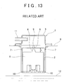
- One known fuel-effusion prevention valve for an automobile fuel system is shown in FIG. 13. The fuel-effusion prevention valve 1 is mounted to an upper wall portion of a
fuel tank 6, and is configured such that afloat 5, which is formed integrally with avalve body 4, is provided at an upper portion inside a space defined by acase 2 that is inserted into thefuel tank 6 and covered from above with acover 3. - Also, a
valve seat 8 having anopening 9 is provided in generally the center in the top surface of thecase 2. A plurality ofvent holes 7 formed in the upper side wall of thecase 2 allow fuel vapor to escape, while a plurality offuel entrance holes 10 are provided in the bottom surface of thecase 2. - During normal operation, the
float 5 is positioned low in thecase 2 so theopening 9 is open. Accordingly, if fuel vapor is produced due to, for example, an increase in temperature within thefuel tank 6, that fuel vapor flows through thevent holes 7 and into thecase 2. The fuel vapor then flows through theopening 9 and through apassage 11 to a canister, not shown, where it is adsorbed by an adsorbent provided in the canister. - When the vehicle bounces up and down or turns, for example, the level of the fuel in the
fuel tank 6 fluctuates greatly. When this happens, some fuel enters thecase 2 through thefuel entrance holes 10 and pushes thefloat 5 up. As a result, thevalve body 4, which is formed on the top portion of thefloat 5, abuts thevalve seat 8 in which theopening 9 is formed, thereby closing off theopening 9 and preventing fuel from flowing into the canister through theopening 9 and thepassage 11. - In the fuel-effusion prevention valve 1 shown in FIG. 13, a large portion of the
case 2 is housed within thefuel tank 6, so the distance h between thefloat 5 and theopening 9 is small. As a result, fuel that enters thecase 2 when the vehicle bounces up and down or turns may flow out of thecase 2 through theopening 9 before theopening 9 is closed by thevalve body 4. Fuel adhering to the top surface of thefloat 5 may also flow out of thecase 2 through theopening 9 when vibrations of the vehicle cause theopening 9 to open briefly from a closed position. - The fuel-effusion prevention valve 1 shown in FIG. 14 was designed to minimize these sorts of adverse effects. Compared with the fuel-effusion prevention valve 1 shown in FIG. 13, this fuel-effusion prevention valve 1 shown in FIG. 14 is configured such that the
valve seat 8, in which theopening 9 is formed, is located above thefuel tank 6. All other structure is the same. - Locating the
valve seat 8 in which theopening 9 is formed above thefuel tank 6 in this way increases the distance H between the top surface of thefloat 5 and theopening 9. As a result, fuel that enters thecase 2 when the vehicle bounces up and down or turns is prevented from flowing out of thecase 2 through the opening 9 before theopening 9 can be closed by thevalve body 4. Moreover, fuel adhering to the top surface of thefloat 5 is prevented from flowing out of thecase 2 through the opening 9 when theopening 9 is supposed to be closed but opens briefly from vibrations of the vehicle (Japanese Patent Application Publication No. JP-A-8-244477). - In recent years, however, there has been a demand for automobiles to have roomier interiors. As a result, vehicle floors are becoming lower and lower. As vehicle floors become lower, fuel tanks are becoming flatter, and there is no longer room for anything to protrude above it.
- Therefore, the fuel-effusion prevention valve 1 of the shape shown in FIG. 14 is cannot be used with a
flat gas tank 6, and the fuel-effusion prevention valve 1 of the shape shown in FIG. 13 is unsuitable for use because of the deficiencies identified above. - The invention thus aims to provide a fuel-effusion prevention valve which prevents fuel from flowing out to a canister when a vehicle bounces up and down or turns or the like, even when there is not much distance between the top surface of the float and an opening formed in the top surface of the case.
- A fuel-effusion prevention valve according to one aspect of the invention includes a case in which an open portion is formed and which is mounted inside a fuel tank; and a valve seat which is formed in the open portion; and a float which has a valve body able to close off the open portion of the valve seat and which moves freely up and down in the case. Further, at least one communicating passage which extends from a top surface to a bottom surface of the float is formed in the float.
- According to this aspect of the invention as well, forming at least one communicating passage in the float which extends from the top surface to the bottom surface enables any fuel which may have entered the case from the fuel tank when the vehicle bounced up and down or turned and reached the top surface of the float, to flow down to the lower portion of the float through the communicating passage and return to the fuel tank. As a result, it is possible to reduce the amount of fuel that flows out to the canister and increase the reliability of the fuel-effusion prevention valve.
- In this aspect of the invention, a plurality of the communicating passages may also be formed at substantially equidistant intervals concentrically centered around the valve body.
- In the foregoing aspect of the invention, a beveled depression may also be formed at the peripheral edge of each communicating passage in the top surface of the float.
- Further, in the foregoing aspect of the invention, the beveled depression may also be formed concentrically centered around the valve body.
- This aspect of the invention thus enables fuel which has entered the area above the float to quickly be returned to below the float via the communicating passages which are close. Accordingly, it is possible to reduce the amount of fuel that flows out to the canister and increase the reliability of the fuel-effusion prevention valve.
- In this aspect of the invention, a support member which supports the float when the valve is open may further be provided below the float in the case. This support member may be configured to interrupt the flow of fuel from the communicating passage into an area enclosed by the support member and an inside wall surface of the case when the float abuts the support member.
- According to this aspect of the invention, if fuel from the fuel tank enters the case when the vehicle bounces up and down or turns, that fuel will no longer reach the top surface of the float directly through the opening in the lower portion of the communicating passage and flow out of the case through the opening formed therein.
- In this aspect of the invention, a depression may be formed on an inner peripheral side of a portion of the support member that abuts the float, in an upper portion of the support member, and a hole may be formed in the depression.
- According to this aspect of the invention, fuel that flows from above the float to below the float through the communicating passage can be returned to the fuel tank through the hole formed in the upper portion of the support member.
- In this aspect of the invention, the float may be configured such that a portion of the bottom portion thereof is positioned above the area enclosed by the inside wall surface of the case and a side wall surface of the support member.
- According to this aspect of the invention, fuel from the fuel tank that entered the case when the vehicle bounced up and down or turned flows into the narrow area between the inside wall surface of the case and the side wall surface of the support member. As it does so, the velocity with which the fuel rises increases so that it strikes the bottom portion of the float at a high velocity. As a result, the float quickly moves upward, closing the opening formed in the case, thereby preventing fuel from flowing out. Moreover, it takes less time for the valve body of the float to abut the valve seat, which makes it possible to more reliably prevent fuel from flowing out of the
case 30. - In the foregoing aspect of the invention, the float may be configured such that a bottom portion of the float includes a skirt portion around the periphery of the float.
- According to this aspect of the invention, even if the height of the float has to be reduced because the fuel tank is made flat, the skirt portion enables the effective height of the float to actually be increased. Therefore, vertical movement of the float is made smooth and the time it takes for the float to move up to where it abuts the valve seat is reduced. As a result, it is possible to more reliably prevent fuel from flowing out to the canister.
- In the foregoing aspect of the invention, a groove may also be formed in a circumferential direction in a side wall surface of the float.
- According to this aspect of the invention, fuel that has entered the case then enters the groove, which increases the force pushing the float upwards. Further, the contact area between the inside wall surface of the case and the outer peripheral surface of the float is reduced, which improves the response of the float to upward movement. As a result, it takes less time for the float to close the valve, which makes it possible to more reliably prevent fuel from flowing out of the canister.
- In the foregoing aspect of the invention, the fuel-effusion prevention valve may be configured to further include a crank-shaped flange portion. This flange portion may be attached to an upper portion of the fuel tank, and a vent hole may be formed in a side surface of the upper portion of the case that is adjacent to a middle vertical portion of the flange portion.
- According to this aspect of the invention, fuel is prevented from entering the case directly through the vent hole even if fuel in the fuel tank surges up violently when the vehicle bounces up and down or turns.
- The foregoing and/or further objects, features and advantages of the invention will become more apparent from the following description of preferred embodiments with reference to the accompanying drawings, in which the same or corresponding portions are denoted by the same reference numerals and wherein:
- FIG. 1 is an overall sectional view of a fuel-effusion prevention valve according to the invention when the valve is open;
- FIG. 2 is an overall sectional view of the fuel-effusion prevention valve according to the invention when the valve is closed;
- FIG. 3 is a bottom view of the fuel-effusion prevention valve according to the invention;
- FIG. 4 is a back view of the fuel-effusion prevention valve according to the invention;
- FIG. 5 is a sectional view of a fixing member of the fuel-effusion prevention valve according to the invention;
- FIG. 6 is a bottom view of the fixing member of the fuel-effusion prevention valve according to the invention;
- FIG. 7 is a back view of the fixing member of the fuel-effusion prevention valve according to the invention;
- FIG. 8 is a sectional view of a float of the fuel-effusion prevention valve according to the invention;
- FIG. 9 is a plan view of the float of the fuel-effusion prevention valve according to the invention;
- FIG. 10 is a bottom view of the float of the fuel-effusion prevention valve according to the invention;
- FIG. 11 is a sectional view of a first modified example of the float of the fuel-effusion prevention valve according to the invention;
- FIG. 12 is a sectional view of a second modified example of the float of the fuel-effusion prevention valve according to the invention;
- FIG. 13 is a sectional view of a fuel-effusion prevention valve of related art; and
- FIG. 14 is a sectional view of a fuel-effusion prevention valve of other related art.
- FIGS. 1 and 2 are overall sectional views showing a fuel-effusion prevention valve when the valve is open and closed, respectively. FIG. 3 is a bottom view of the fuel-effusion prevention valve. The fuel-effusion prevention valve of this invention may be used for any number of applications, but the following description describes its use in a fuel system of an automobile.
- A fuel-
effusion prevention valve 20 includes acase 30, afloat 60 arranged within thecase 30, and a fixingmember 42 that is formed of asupport portion 55 and aflange portion 45, which fixes thecase 30 to afuel tank 25, and the like. - The
case 30 is a generally bell-shaped member made of resin that is open at the bottom. Anopening 31 is formed in the center of the upper wall portion of thecase 30, and avalve seat 33 is formed in aninternal space 32 below theopening 31. Further, apassage 34, which encloses theopening 31, is formed integrally with thecase 30. Thispassage 34 is connected to a canister, not shown, provided outside of thefuel tank 25 via a pipe, also not shown. - A plurality of
vertical ribs 35 is arranged at equidistant intervals along the inside wall surface in thecase 30. Theribs 35 maintain a space between the inside wall surface of thecase 30 and the side wall surface of thefloat 60, thus forming passages for the fuel vapor and the like. The peripheral part of theribs 35 also guides thefloat 60 as it moves vertically. - A plurality of
protrusions 36 for attaching the fixing member hangs down from the bottom portion of thecase 30. Theseprotrusions 36 are angled outwards somewhat from the outside surface of thecase 30. Agrooved portion 37 is formed in the outer periphery of the base portion of theprotrusions 36, which engages with aninsertion hole 51 in theflange portion 45, to be described later. Also, a retainingmember 38 is formed on a side portion of thecase 30 on the side opposite thepassage 34. This retainingmember 38 has a vertical through-hole with which a retainingpiece 49 of theflange portion 45, to be described later, engages. Also, twovent holes 39 are provided in the outside surface of thecase 30 above the retainingmember 38, as shown in FIG. 4, to allow fuel vapor into thecase 30. - The fixing
member 42 is a resin or metal member which includes theflange portion 45 and thesupport portion 55, both of which are integrally formed. It should be noted that while theflange portion 45 and thesupport portion 55 are integrally formed in this example embodiment, they may also be formed separately and then assembled together into a single unit. - The
flange portion 45 includes an upper endhorizontal portion 46, a middlevertical portion 47, and a lower endhorizontal portion 48, as shown in the sectional view of FIG. 5, the bottom view of FIG. 6, and the back view of FIG. 7. The upper endhorizontal portion 46 and the middlevertical portion 47 are both rectangular while the lower endhorizontal portion 48 is generally disc-shaped. The upper endhorizontal portion 46, the middlevertical portion 47, and the lower endhorizontal portion 48 together form a crank shape, as shown in FIGS. 1 and 5. - The upper surface of the upper end
horizontal portion 46 is fixed to the upper surface of thefuel tank 25 by means such as welding or an adhesive. The retainingpiece 49 is attached to the surface of the middlevertical portion 47 that is on the side opposite the upper endhorizontal portion 46. When attaching thecase 30 to the fixingmember 42, the tip of the retainingpiece 49 is inserted into the through-hole of the retainingmember 38 formed on the side portion of thecase 30 such that thecase 30 is supported from the side surface. As a result, the twovent holes 39 for fuel vapor or the like shown in FIG. 4 which are provided in the upper outside surface of thecase 30 are blocked by the middlevertical portion 47, which minimizes the possibility that fuel inside thefuel tank 25 entering thecase 30 through the vent holes 39. - The lower end
horizontal portion 48 is generally disc-shaped with thecylindrical support portion 55 protruding upward formed by drawing or the like at the center portion. A plurality (six are shown in the drawing) offuel entrance ports 50 for allowing fuel to flow from thecase 30 to thefuel tank 25 are formed in the outer periphery of the lower endhorizontal portion 48. In addition, a plurality (three are shown in the drawing) of insertion holes 51 into which theprotrusions 36 which hang down from the bottom portion of thecase 30 are inserted are formed on the outer periphery of thefuel entrance ports 50. - The
support portion 55 is formed in a hollow cylinder shape by, for example, drawing the center portion of the lower endhorizontal portion 48. Thesupport portion 55 corresponds to a support member which supports thefloat 60. Arecess 56 for supporting one end of a spring, to be described later, is formed in the top surface of thesupport portion 55. Further, ahole 57 which provides communication between thefuel tank 25 and the inside of thecase 30 is formed in the center of therecess 56. - The
float 60 is a resin member with a generally rectangular cross-section and a circular planar surface, as shown in the sectional view of FIG. 8, the plan view of FIG. 9, and the bottom view of FIG. 10. Avalve body 61 is formed in the center portion on the top surface of thefloat 60. A plurality (eight are shown in the drawing) of communicatingpassages 68 are formed around thevalve body 61 to enable communication between the areas above and below thefloat 60. - A
beveled depression 64 is formed at the peripheral edge of the communicatingpassages 68 on the top side of thefloat 60. Thebeveled depression 64 is formed concentrically centered around thevalve body 61. Also, abottom recess 65 that is depressed upwards is formed in the bottom portion of thefloat 60. A lower endopen portion 67 at the other end of the communicatingpassages 68 is formed in thebottom recess 65. - The lower end
open portion 67 is formed in a position in which it becomes blocked off from a ring-shapedpassage 71 formed by the inside surface of thecase 30 and the side wall surface of thesupport portion 55 when thevalve body 61 shown in FIG. 1 with the valve open and thefloat 60 and thesupport portion 55 abut one another. The communicatingpassage 68 in this invention may also be formed of a ring-shaped ascending recessedportion 66 in which a portion of thebottom recess 65 of thefloat 60 is formed depressed farther upwards than the rest of thebottom recess 65, and a communicatingport 62 which forms an open portion in the top portion of thefloat 60. In other words, any configuration can be used as long as it allows communication between the area above thefloat 60 and the area below thefloat 60 so that fuel which has made its way above thefloat 60 is able to flow downward. - Also, the diameter D of the
float 60 is greater than the diameter d of thesupport portion 55, as shown in FIG. 2. Fuel that enters the ring-shapedpassage 71 formed by the inside surface of thecase 30 and the side wall surface of thesupport portion 55, and strikes the bottom surface of thefloat 60, which raises raising thefloat 60. - Assembly of the fuel-
effusion prevention valve 20 will now be described. During assembly, thecase 30 is first placed upside down. Thefloat 60 is then inserted into thecase 30 by seating thevalve body 61 in thevalve seat 33 formed at theopening 31 of thecase 30. Next, a coil-shapedspring 70 is inserted into the ring-shaped ascending recessedportion 66 formed in thefloat 60. The diameter of thespring 70 is substantially the same as the diameter of the ring-shaped ascending recessedportion 66. Thespring 70 helps to lift thefloat 60 when fuel enters thecase 30. - Next, the fixing
member 42 is inserted into the bottom portion of thecase 30. At this time, the other end portion of thespring 70 abuts therecess 56 formed in the top surface of thesupport portion 55. The bottom portion of thecase 30 is covered by placing the lower endhorizontal portion 48 of the fixingmember 42 so that it opposes the bottom portion of thecase 30 and inserting theprotrusions 36 which hang down from the bottom portion of thecase 30 into the insertion holes 51 formed in the lower endhorizontal portion 48. Theprotrusions 36 extend slightly outward at the tips and have spring to them. - Thus, the
protrusions 36 are pressed to fit into the insertion holes 51. After theprotrusions 36 are fitted into the insertion holes 51, thegrooved portions 37 formed in the outer peripheral portion of theprotrusions 36 engage with the edges of the insertion holes 51, thus completing assembly of the members. In this manner, the fixingmember 42 and thecase 30 can be assembled together in a one-touch operation, which improves productivity. The retainingpiece 49 provided on theflange portion 45 engages with the retainingmember 38 provided on the side portion of thecase 30 at the same time theprotrusions 36 are inserted into the insertion holes 51. - The fuel-
effusion prevention valve 20 is complete after the fixingmember 42 and thecase 30 have been assembled and thecase 30 is placed right-side up, in the manner shown in FIG. 1. The upper end of the upper endhorizontal portion 46 of theflange portion 45 is then attached to the inside surface of the upper portion of thefuel tank 25 by welding or with an adhesive or the like. - When the
case 30 is right-side up, the outer diameter d of thesupport portion 55 is smaller than both the inner diameter of thecase 30 and the outer diameter D of thefloat 60, resulting in the formation of the ring-shapedpassage 71 between the inner wall portion of thecase 30 and the side wall surface of thesupport portion 55. - Next, the operation will now be described. During normal operation, the
fuel level 26 is located as shown in FIGS. 1 and 2. Fuel vapor produced in thefuel tank 25 enters thecase 30 through the vent holes 39 and thefuel entrance ports 50 and flows to the canister via theopening 31 and thepassage 34. Even if thefuel tank 25 vibrates and thefuel level 26 rises so that fuel blocks off thefuel entrance ports 50, the fuel vapor can still be discharged without interference through the vent holes 39 because they are provided higher in thecase 30. - When the vehicle bounces up and down or turns, the
fuel level 26 undulates greatly and fuel enters thecase 30 through thefuel entrance ports 50. The fuel then travels from the ring-shapedpassage 71 between the inside wall portion of thecase 30 and the side wall surface of thefloat 60, and may flow through theopening 31 into thepassage 34. - As the fuel travels through the ring-shaped
passage 71, it accelerates and strikes the flat portion of the lower portion of thefloat 60. As a result, thefloat 60 is quickly lifted up so that thevalve body 61 abuts thevalve seat 33, to close off theopening 31. Therefore, even if the fuel were to reach the top surface of thefloat 60, little or none would flow out of thecase 30 through theopening 31 because thefloat 60 abuts thecase 30. - When the
valve body 61 is in the valve-open position shown in FIG. 1, fuel is prevented from flowing between the lower endopen portion 67 of the float 60 (shown in FIG. 8) and the ring-shapedpassage 71. Thus, it is possible to minimize as the amount of fuel that flows up through the ring-shapedpassage 71 reaching the top surface of thefloat 60 via the communicatingpassage 68. Thus, minimizing the amount of fuel that flows out of thecase 30 through theopening 31 before thevalve body 61 closes the valve. - Fuel that has reached the top surface of the
float 60 accumulates in the beveled depression 64 (shown in FIG. 8) formed in the top surface, and is then returned to thefuel tank 25 via the communicatingport 62 and the ring-shaped ascending recessedportion 66, as shown by the arrows. Moreover, when thevalve body 61 is in the valve-open position shown in FIG. 1, fuel that flows down through the communicatingport 62 and the ring-shaped ascending recessedportion 66 accumulates in therecess 56 formed in the top surface of thesupport portion 55 and is then returned to thefuel tank 25 through thehole 57 formed in the center of therecess 56, as shown by the arrows. - FIG. 11 shows a first modified example of the
float 60. Thefloat 60 according to this first modified, the bottom end of thefloat 60 includes acylindrical skirt portion 75 around the periphery of thefloat 60. If the height of thefuel tank 25 is reduced, the height of the fuel-effusion prevention valve 20, and consequently thefloat 60, is also reduced. Thus, it is no longer possible to increase the height of thefloat 60. As a result, thefloat 60 may move upward off-center, for example, which would inhibit it from moving smoothly up and down along theribs 35 inside thecase 30. - With the
float 60 according to the first modified example, theskirt portion 75 enables the height of the side wall surface of thefloat 60 along theribs 35 to be increased, thus preventing adverse effects such as those described above. In FIG. 11, thefloat 60 and theskirt portion 75 are shown integrally formed. Alternatively, however, both members may be formed separately and then made into a single unit by means such as welding or an adhesive or the like. Alternatively, thecylindrical skirt portion 75 does not have to be continuous, but rather may be shaped in a series of intermittent arcs. - FIG. 12 shows a second modified example of the
float 60. Thefloat 60 according to this second modified example has a groove formed in the circumferential direction in the side wall surface of thefloat 60. In this example, a plurality of the ring-shapedgrooves 76 are formed in the side wall surface of thefloat 60. According to this configuration, the surface area of the side wall surface of thefloat 60 increases, which increases the force pushing up on thefloat 60 from fuel that has entered thecase 30. This configuration also reduced the contact area between theribs 35 and the side wall surface of thefloat 60. As a result, thevalve body 61 of thefloat 60 can be moved to abut thevalve seat 33 more quickly, making it possible to more reliably prevent an outflow of fuel. Further, theskirt portion 75 shown in FIG. 11 can also be added to thefloat 60 in this example. The groove formed in the circumferential direction does not have to be in the shape of a continuous ring. Alternatively, it may be in the shape of a spiral. - This invention is not limited to the configuration of the foregoing example embodiment. To the contrary, changes in design may be made as appropriate within the intended scope of the invention.
Claims (10)
- A fuel-effusion prevention valve which includes a case (30) in which an open portion (31) is formed and which is mounted inside a fuel tank (25), and a valve seat (33) which is formed in the open portion (31), and a float (60) which has a valve body (61) able to close off the open portion of the valve seat (33) and which moves freely up and down in the case (30), characterized by comprising:at least one communicating passage (68) which extends from a top surface to a bottom surface of the float (60) formed in the float (60).
- The fuel-effusion prevention valve according to claim 1, wherein a plurality of the communicating passages (68) are formed at substantially equidistant intervals concentrically centered around the valve body (61).
- The fuel-effusion prevention valve according to claim 1 or 2, wherein a beveled depression (64) is formed at the peripheral edge of each communicating passage (68) in the top surface of the float (60).
- The fuel-effusion prevention valve according to claim 3, wherein the beveled depression (64) is formed concentrically centered around the valve body (61).
- The fuel-effusion prevention valve according to any one of claims 1 to 4, characterized by further comprising:a support member (55), provided below the float (60) that supports the float (60) when the valve is open, wherein the support member (55) interrupts the flow of fuel from the communicating passage (68) into an area enclosed by the support member (55) and an inside wall surface of the case (30) when the float abuts (60) the support member (55).
- The fuel-effusion prevention valve according to claim 5, wherein a depression (56) is formed on an inner peripheral side of a portion of the support member (55) that abuts the float (60), in an upper portion of the support member (55), and a hole (57) is formed in the depression (56).
- The fuel-effusion prevention valve according to claim 5 or 6, wherein a portion of a bottom portion of the float (60) is positioned above the area (71) enclosed by the inside wall surface of the case (30) and a side wall surface of the support member (55).
- The fuel-effusion prevention valve according to any one of claims 1 to 7, characterized by further comprising:a bottom portion of the float includes a skirt portion (75) around the periphery of the float (60).
- The fuel-effusion prevention valve according to any one of claims 1 to 8, wherein a groove (76) is formed in a circumferential direction in a side wall surface of the float (60).
- The fuel-effusion prevention valve according to any one of claims 1 to 9, characterized by further comprising:a crank-shaped flange portion (45), wherein the flange portion (45) is attached to an upper portion of the fuel tank (25), and a vent hole (39) is formed in a side surface of an upper portion of the case (30) that is adjacent to a middle vertical portion (47) of the flange portion (45).
Applications Claiming Priority (1)
| Application Number | Priority Date | Filing Date | Title |
|---|---|---|---|
| JP2005014313A JP2006200469A (en) | 2005-01-21 | 2005-01-21 | Fuel spill prevention valve |
Publications (2)
| Publication Number | Publication Date |
|---|---|
| EP1683672A2 true EP1683672A2 (en) | 2006-07-26 |
| EP1683672A3 EP1683672A3 (en) | 2008-01-09 |
Family
ID=36190401
Family Applications (1)
| Application Number | Title | Priority Date | Filing Date |
|---|---|---|---|
| EP20060001148 Withdrawn EP1683672A3 (en) | 2005-01-21 | 2006-01-19 | Fuel-effusion prevention valve |
Country Status (4)
| Country | Link |
|---|---|
| US (1) | US20060162777A1 (en) |
| EP (1) | EP1683672A3 (en) |
| JP (1) | JP2006200469A (en) |
| CA (1) | CA2532921A1 (en) |
Cited By (2)
| Publication number | Priority date | Publication date | Assignee | Title |
|---|---|---|---|---|
| CN103363136A (en) * | 2013-08-02 | 2013-10-23 | 苏州圆能动力科技有限公司 | External anti-tipping valve |
| CN104454269A (en) * | 2014-12-04 | 2015-03-25 | 苏州圆能动力科技有限公司 | Steel ball type fuel oil control valve |
Families Citing this family (4)
| Publication number | Priority date | Publication date | Assignee | Title |
|---|---|---|---|---|
| JP2006290085A (en) * | 2005-04-08 | 2006-10-26 | Kyosan Denki Co Ltd | Seal structure of float valve |
| JP7010651B2 (en) * | 2017-10-16 | 2022-01-26 | 株式会社パイオラックス | Fuel tank valve device |
| JP6747459B2 (en) * | 2018-01-19 | 2020-08-26 | 京三電機株式会社 | Ventilation control valve for fuel tank |
| US10843555B2 (en) * | 2018-09-28 | 2020-11-24 | Toyoda Gosei Co., Ltd. | Opening/closing device of fuel tank |
Citations (1)
| Publication number | Priority date | Publication date | Assignee | Title |
|---|---|---|---|---|
| EP1184221A2 (en) | 2000-08-29 | 2002-03-06 | Nifco Inc. | Valve for vehicle fuel tank |
Family Cites Families (8)
| Publication number | Priority date | Publication date | Assignee | Title |
|---|---|---|---|---|
| US2086236A (en) * | 1936-01-17 | 1937-07-06 | Houde Eng Corp | Valving assembly for hydraulic shock absorbers |
| US4413652A (en) * | 1981-03-30 | 1983-11-08 | Oil Air Industries, Inc. | Gas-liquid accumulator |
| FR2636573B1 (en) * | 1988-09-19 | 1990-12-14 | Peugeot | TIMED AERATION DEVICE FOR A FUEL TANK |
| US5605175A (en) * | 1995-05-24 | 1997-02-25 | Bergsma; Rudolph | Fluid responsive vent control valve with peel-away opening action |
| FR2779100B1 (en) * | 1998-05-28 | 2000-08-18 | Journee Paul Sa | MOTOR VEHICLE FUEL TANK RELEASING DEVICE |
| CA2335165C (en) * | 2000-02-11 | 2005-07-12 | Stant Manufacturing Inc. | Weldable mount for fuel system component |
| JP3973205B2 (en) * | 2002-08-07 | 2007-09-12 | 株式会社ニフコ | Fuel shut-off valve device |
| JP3953916B2 (en) * | 2002-08-23 | 2007-08-08 | 豊田合成株式会社 | Fuel tank fuel spill regulating device |
-
2005
- 2005-01-21 JP JP2005014313A patent/JP2006200469A/en active Pending
-
2006
- 2006-01-13 CA CA 2532921 patent/CA2532921A1/en not_active Abandoned
- 2006-01-13 US US11/331,120 patent/US20060162777A1/en not_active Abandoned
- 2006-01-19 EP EP20060001148 patent/EP1683672A3/en not_active Withdrawn
Patent Citations (1)
| Publication number | Priority date | Publication date | Assignee | Title |
|---|---|---|---|---|
| EP1184221A2 (en) | 2000-08-29 | 2002-03-06 | Nifco Inc. | Valve for vehicle fuel tank |
Cited By (3)
| Publication number | Priority date | Publication date | Assignee | Title |
|---|---|---|---|---|
| CN103363136A (en) * | 2013-08-02 | 2013-10-23 | 苏州圆能动力科技有限公司 | External anti-tipping valve |
| CN103363136B (en) * | 2013-08-02 | 2016-01-20 | 苏州圆能动力科技有限公司 | A kind of external anti-dumping pressure control valve |
| CN104454269A (en) * | 2014-12-04 | 2015-03-25 | 苏州圆能动力科技有限公司 | Steel ball type fuel oil control valve |
Also Published As
| Publication number | Publication date |
|---|---|
| EP1683672A3 (en) | 2008-01-09 |
| US20060162777A1 (en) | 2006-07-27 |
| JP2006200469A (en) | 2006-08-03 |
| CA2532921A1 (en) | 2006-07-21 |
Similar Documents
| Publication | Publication Date | Title |
|---|---|---|
| JP5437784B2 (en) | Valve device for fuel tank | |
| EP1683672A2 (en) | Fuel-effusion prevention valve | |
| US7717126B2 (en) | Float valve structure | |
| US20080251134A1 (en) | Fuel cutoff valve | |
| US7934514B2 (en) | Fuel cutoff valve | |
| JPH01158278A (en) | Fuel block valve | |
| US8720471B2 (en) | Fuel cutoff valves | |
| JP6295905B2 (en) | Fuel shut-off valve | |
| US5638856A (en) | Stop valve structure | |
| US7963296B2 (en) | Fuel cutoff valve | |
| JP2009202703A (en) | Fuel shut-off valve | |
| US10279679B2 (en) | Valve device | |
| US8490642B2 (en) | Fuel-outflow check valve | |
| US20110005609A1 (en) | Fuel cut-off valve | |
| US20060225785A1 (en) | Sealing structure of float valve | |
| US8776823B2 (en) | Fuel shut-off valves | |
| JP2010105523A (en) | Fuel shut-off valve | |
| WO2012118118A1 (en) | Fuel shutoff valve | |
| JP2009279981A (en) | Fuel shut-off valve | |
| JP4207875B2 (en) | Fuel shut-off valve | |
| JP4407534B2 (en) | Fuel shut-off valve | |
| WO2022080302A1 (en) | Full tank regulation valve | |
| WO2022168676A1 (en) | Valve device | |
| JP2007146794A (en) | Fuel shutoff valve | |
| JP2009078647A (en) | Fuel shutoff valve |
Legal Events
| Date | Code | Title | Description |
|---|---|---|---|
| PUAI | Public reference made under article 153(3) epc to a published international application that has entered the european phase |
Free format text: ORIGINAL CODE: 0009012 |
|
| AK | Designated contracting states |
Kind code of ref document: A2 Designated state(s): AT BE BG CH CY CZ DE DK EE ES FI FR GB GR HU IE IS IT LI LT LU LV MC NL PL PT RO SE SI SK TR |
|
| AX | Request for extension of the european patent |
Extension state: AL BA HR MK YU |
|
| PUAL | Search report despatched |
Free format text: ORIGINAL CODE: 0009013 |
|
| AK | Designated contracting states |
Kind code of ref document: A3 Designated state(s): AT BE BG CH CY CZ DE DK EE ES FI FR GB GR HU IE IS IT LI LT LU LV MC NL PL PT RO SE SI SK TR |
|
| AX | Request for extension of the european patent |
Extension state: AL BA HR MK YU |
|
| 17P | Request for examination filed |
Effective date: 20080617 |
|
| AKX | Designation fees paid |
Designated state(s): DE FR GB |
|
| GRAP | Despatch of communication of intention to grant a patent |
Free format text: ORIGINAL CODE: EPIDOSNIGR1 |
|
| STAA | Information on the status of an ep patent application or granted ep patent |
Free format text: STATUS: THE APPLICATION IS DEEMED TO BE WITHDRAWN |
|
| 18D | Application deemed to be withdrawn |
Effective date: 20091125 |