JP2006200469A - Fuel spill prevention valve - Google Patents
Fuel spill prevention valve Download PDFInfo
- Publication number
- JP2006200469A JP2006200469A JP2005014313A JP2005014313A JP2006200469A JP 2006200469 A JP2006200469 A JP 2006200469A JP 2005014313 A JP2005014313 A JP 2005014313A JP 2005014313 A JP2005014313 A JP 2005014313A JP 2006200469 A JP2006200469 A JP 2006200469A
- Authority
- JP
- Japan
- Prior art keywords
- float
- fuel
- case
- prevention valve
- ring
- Prior art date
- Legal status (The legal status is an assumption and is not a legal conclusion. Google has not performed a legal analysis and makes no representation as to the accuracy of the status listed.)
- Pending
Links
Images


Classifications
-
- F—MECHANICAL ENGINEERING; LIGHTING; HEATING; WEAPONS; BLASTING
- F16—ENGINEERING ELEMENTS AND UNITS; GENERAL MEASURES FOR PRODUCING AND MAINTAINING EFFECTIVE FUNCTIONING OF MACHINES OR INSTALLATIONS; THERMAL INSULATION IN GENERAL
- F16K—VALVES; TAPS; COCKS; ACTUATING-FLOATS; DEVICES FOR VENTING OR AERATING
- F16K24/00—Devices, e.g. valves, for venting or aerating enclosures
- F16K24/04—Devices, e.g. valves, for venting or aerating enclosures for venting only
- F16K24/042—Devices, e.g. valves, for venting or aerating enclosures for venting only actuated by a float
- F16K24/044—Devices, e.g. valves, for venting or aerating enclosures for venting only actuated by a float the float being rigidly connected to the valve element, the assembly of float and valve element following a substantially translational movement when actuated, e.g. also for actuating a pilot valve
-
- B—PERFORMING OPERATIONS; TRANSPORTING
- B60—VEHICLES IN GENERAL
- B60K—ARRANGEMENT OR MOUNTING OF PROPULSION UNITS OR OF TRANSMISSIONS IN VEHICLES; ARRANGEMENT OR MOUNTING OF PLURAL DIVERSE PRIME-MOVERS IN VEHICLES; AUXILIARY DRIVES FOR VEHICLES; INSTRUMENTATION OR DASHBOARDS FOR VEHICLES; ARRANGEMENTS IN CONNECTION WITH COOLING, AIR INTAKE, GAS EXHAUST OR FUEL SUPPLY OF PROPULSION UNITS IN VEHICLES
- B60K15/00—Arrangement in connection with fuel supply of combustion engines or other fuel consuming energy converters, e.g. fuel cells; Mounting or construction of fuel tanks
- B60K15/03—Fuel tanks
- B60K15/035—Fuel tanks characterised by venting means
- B60K15/03519—Valve arrangements in the vent line
-
- Y—GENERAL TAGGING OF NEW TECHNOLOGICAL DEVELOPMENTS; GENERAL TAGGING OF CROSS-SECTIONAL TECHNOLOGIES SPANNING OVER SEVERAL SECTIONS OF THE IPC; TECHNICAL SUBJECTS COVERED BY FORMER USPC CROSS-REFERENCE ART COLLECTIONS [XRACs] AND DIGESTS
- Y10—TECHNICAL SUBJECTS COVERED BY FORMER USPC
- Y10T—TECHNICAL SUBJECTS COVERED BY FORMER US CLASSIFICATION
- Y10T137/00—Fluid handling
- Y10T137/2931—Diverse fluid containing pressure systems
- Y10T137/3003—Fluid separating traps or vents
- Y10T137/3084—Discriminating outlet for gas
- Y10T137/309—Fluid sensing valve
- Y10T137/3099—Float responsive
Landscapes
- Engineering & Computer Science (AREA)
- General Engineering & Computer Science (AREA)
- Mechanical Engineering (AREA)
- Chemical & Material Sciences (AREA)
- Sustainable Development (AREA)
- Sustainable Energy (AREA)
- Life Sciences & Earth Sciences (AREA)
- Combustion & Propulsion (AREA)
- Transportation (AREA)
- Cooling, Air Intake And Gas Exhaust, And Fuel Tank Arrangements In Propulsion Units (AREA)
- Self-Closing Valves And Venting Or Aerating Valves (AREA)
- Float Valves (AREA)
- Supplying Secondary Fuel Or The Like To Fuel, Air Or Fuel-Air Mixtures (AREA)
Abstract
Description
本願発明は、燃料流出防止弁、例えば自動車等の燃料タンク内の燃料蒸発ガスを燃料タンク外に設けたキャニスタへ流出させてキャニスタの吸着剤に吸着させ、さらに燃料油面上昇時に燃料タンク内の燃料がキャニスタへ流出することを防止する燃料流出防止弁に関する。 The present invention provides a fuel spill prevention valve, for example, a fuel evaporative gas in a fuel tank of an automobile or the like flows out into a canister provided outside the fuel tank and is adsorbed by an adsorbent of the canister. The present invention relates to a fuel outflow prevention valve that prevents fuel from flowing out into a canister.
従来、自動車用燃料系の燃料流出防止弁として図13に示すものが知られている。この燃料流出防止弁1は、ケース2によって形成される空間内に上部に弁体4を一体に形成したフロート5が設けられてなり、燃料タンク6内にケース2が挿入され、その上方にカバー3を設ける形態で燃料タンク6の上壁部に取り付けられる。
Conventionally, what is shown in FIG. 13 is known as a fuel outflow prevention valve of a fuel system for automobiles. This fuel outflow prevention valve 1 is provided with a
また、前記ケース2の上面略中央には、弁座8が形成される開口9が設けられ、同ケース2の上方側面には、複数の燃料蒸発ガス用の通気孔7が形成され、同ケース2の底面には、複数の燃料出入孔10が設けられる。
In addition, an opening 9 in which a valve seat 8 is formed is provided in the approximate center of the upper surface of the case 2, and a plurality of fuel evaporative
そして、通常時、フロート5は下方に位置し、開口9は開放されているため、燃料タンク6内の温度が上昇する等により燃料タンク6内に燃料蒸発ガスが発生すると、発生した燃料蒸発ガスは、通気孔7からケース2内に入り、開口9からカバー3内に開口される連通路11を経て図示しないキャニスタに至りキャニスタ内に設けられる吸着剤に吸着される。
In normal times, the
車両が上下動したり旋回等すると燃料タンク6内の燃料の油面12が大きく変動する。すると燃料の一部が燃料出入孔10からケース2内に侵入し、侵入した燃料は、フロート5を押し上げる。するとフロート5の上部に形成される弁体4は、開口9に形成される弁座8に当接し、開口9を閉鎖する。そのため、燃料が開口9および連通路11を介してキャニスタに流出することがなくなる。
When the vehicle moves up and down or turns, the
ところで、図13に示す従来例のものは、燃料タンク6内にケース2の大部分が収納配置されるものであり、開口9とフロート5の上面との距離hは短くならざるを得ず、車両の上下動時や旋回時にケース2内に侵入した燃料が、開口9が弁体4により閉鎖される前に開口9外に流出したり、或いはフロート5の上面に付着した燃料が車両の振動で開口9が閉鎖状態から一時的に開放状態になる瞬間に開口9外に流出する恐れがあった。
Incidentally, in the conventional example shown in FIG. 13, most of the case 2 is accommodated in the fuel tank 6, and the distance h between the opening 9 and the upper surface of the
そのような弊害を防止するものとして、図14に示すものが提案されている。この燃料流出防止弁は、図13のものと比べ、開口9に形成される弁座8の位置を燃料タンク6の上方に位置させるもので、その他はほぼ同じ構造からなる。 As a means for preventing such an adverse effect, the one shown in FIG. 14 has been proposed. This fuel outflow prevention valve has a valve seat 8 formed in the opening 9 positioned above the fuel tank 6 as compared with the one shown in FIG.
図14に示すものは、開口9に形成される弁座8の位置が燃料タンク6の上方にあり、開口9とフロート5の上面との距離Hを高くすることができる。そのため、車両の上下動時や旋回時にケース2内に侵入した燃料が開口9が閉鎖される前に開口9外に流出したり、或いはフロート5の上面に付着した燃料が車両の振動で開口9が閉鎖状態から一時的に開放状態になる瞬間に開口9外に流出されることを防止することができる(特許文献1参照)。
In the configuration shown in FIG. 14, the position of the valve seat 8 formed in the opening 9 is above the fuel tank 6, and the distance H between the opening 9 and the upper surface of the
ところで、近年自動車は、ゆとりある車内空間が求められ、車両の低床化が推し進められている。車両の低床化に伴い、燃料タンク6は偏平化され、さらに燃料タンク6の上方に突起物を配置することができない状態にある。 By the way, in recent years, automobiles are required to have a spacious interior space, and the floor of vehicles is being lowered. As the vehicle floor is lowered, the fuel tank 6 is flattened, and the protrusions cannot be disposed above the fuel tank 6.
そのため、図14に示す形状の燃料流出防止弁1は偏平化された燃料タンク6には用いることができず、図13に示す形状の燃料流出防止弁1では、燃料の流出を防止できないためやはり用いることができないという問題がある。
本願発明の目的は、このような問題を解決することで、開口とフロートの上面との距離が短くても車両の上下動時や旋回時等に燃料がキャニスタに流出するのを防止することができる燃料流出防止弁を提供することである。 The object of the present invention is to solve such problems and prevent the fuel from flowing into the canister when the vehicle moves up and down or turns even if the distance between the opening and the upper surface of the float is short. A fuel spill prevention valve is provided.
上記目的を達成するため、本願発明は以下の構成を採用する。 In order to achieve the above object, the present invention adopts the following configuration.
請求項1に係る発明では、燃料タンク内に取り付けられるケースと、該ケース内に形成される空間に上下動自在に設けられるフロートと、該フロートの上部に設けられ、前記ケースの上部開口に形成される弁座と当接自在な弁体とを備えてなる燃料流出防止弁において、前記フロートに上面から下面にいたる複数の連通路を設ける構成。 In the invention according to claim 1, a case mounted in the fuel tank, a float provided in a space formed in the case so as to be movable up and down, and provided in an upper part of the float and formed in an upper opening of the case A fuel outflow prevention valve comprising a valve seat and a valve body that can freely come into contact with each other, wherein the float is provided with a plurality of communication passages from the upper surface to the lower surface.
そして、このような構成により、車両の上下動時や旋回時に燃料タンク内の燃料がケース内に侵入し、フロートの上面に至り、ケースに形成される開口から外に流出しようとしても、フロートの上面に至った燃料は、フロートの上面に開口する複数の連通路よりフロートの下部に戻される。 With such a configuration, even when the vehicle moves up and down or turns, the fuel in the fuel tank enters the case, reaches the upper surface of the float, and flows out of the opening formed in the case. The fuel that has reached the upper surface is returned to the lower portion of the float through a plurality of communication passages that open to the upper surface of the float.
請求項2に係る発明では、前記複数の連通口は、前記弁体の回りに略等間隔に設けられ、また、請求項3に係る発明では、前記複数の連通口の上部開口は、前記弁体回りのフロート上面にリング状に形成される谷部に設けられる構成。そして、このような構成により、フロートの上面のどの位置に燃料が到達したとしても、到達した燃料は素早くその近くの連通口よりフロートの下部に戻される。
In the invention according to claim 2, the plurality of communication ports are provided at substantially equal intervals around the valve body, and in the invention according to
請求項4に係る発明では、前記ケース内の前記フロートの下方には、前記弁体の開弁時に前記フロートを支える支持部材が設けられ、前記弁体の開弁時、前記連通路の下部開口は、前記支持部材により遮蔽される構成。そして、このような構成により、車両の上下動時や旋回時に燃料タンク内の燃料がケース内に侵入した場合、侵入した燃料が連通路の下部開口より直接フロートの上面に至り、ケースに形成される開口から外に流出することはなくなる。 In the invention according to claim 4, a support member that supports the float when the valve body is opened is provided below the float in the case, and when the valve body is opened, a lower opening of the communication path is provided. Is configured to be shielded by the support member. With such a configuration, when the fuel in the fuel tank enters the case when the vehicle moves up and down or turns, the fuel that has entered directly reaches the upper surface of the float from the lower opening of the communication path and is formed in the case. Will not flow out of the opening.
請求項5に係る発明では、前記ケース内壁面と前記支持部材側壁面とでリング状の通路を形成し、該リング状の通路の上方に前記フロートの底部の一部が位置する構成。そして、このような構成により、車両の上下動時や旋回時に燃料タンク内の燃料がケース内に侵入した場合、侵入した燃料は、リング状の通路で絞られるため上昇速度を増し、速い速度でフロートの底部に衝突する。そのため、フロートは即座に上動してケースに形成される開口を閉鎖し、燃料の流出を防止する。
In the invention which concerns on
請求項6に係る発明では、前記フロートの底部外周面にリング状のスカート部を垂下する構成。そして、このような構成により、燃料タンクの偏平化に起因してフロートの高さを低くせざるを得ないとしても、スカート部によりフロートの高さが高くなるため、フロートの上下動が滑らかになる。 In the invention which concerns on Claim 6, the structure which suspends a ring-shaped skirt part from the bottom part outer peripheral surface of the said float. With such a configuration, even if the height of the float has to be lowered due to the flattening of the fuel tank, the height of the float is increased by the skirt, so that the vertical movement of the float is smooth. Become.
請求項7に係る発明では、前記フロートの側壁面にリング状の溝を設ける構成。そして、このような構成により、ケース内に侵入した燃料が溝内に侵入し、フロートを押し上げる力が増し、さらにケース内壁面とフロート外周面との接触面積が減るため、フロート上動のレスポンスが向上する。
In the invention which concerns on
請求項8に係る発明では、前記燃料流出防止弁は、略クランク状のフランジ部で燃料タンクの上部に取り付けられるとともに、該フランジ部と対向する前記ケースの上部側面に通気孔を設ける構成。そして、このような構成により、車両の上下動時や旋回時に燃料タンク内の燃料が激しく波立ったとしても、通気孔から燃料が直接ケース内に侵入することはなくなる。 The invention according to claim 8 is configured such that the fuel outflow prevention valve is attached to the upper portion of the fuel tank with a substantially crank-shaped flange portion, and a vent hole is provided on the upper side surface of the case facing the flange portion. With such a configuration, even if the fuel in the fuel tank swells violently when the vehicle moves up and down or turns, the fuel does not directly enter the case from the vent hole.
請求項1に係る発明では、フロートに上面から下面にいたる複数の連通路を設けることにより、車両の上下動時や旋回時に燃料タンク内の燃料がケース内に侵入し、フロートの上面に至ったとしても、フロートの上面に開口する複数の連通路よりフロートの下部に流下し燃料タンク内に戻すことができるため、キャニスタに流出する燃料を低減することができ、燃料流出防止弁の信頼性を高めることができる。 In the invention according to claim 1, by providing the float with a plurality of communication passages from the upper surface to the lower surface, the fuel in the fuel tank enters the case when the vehicle moves up and down or turns, and reaches the upper surface of the float. However, since it can flow down to the lower part of the float from the plurality of communication passages opened on the upper surface of the float and return to the fuel tank, the fuel flowing out to the canister can be reduced, and the reliability of the fuel outflow prevention valve is improved. Can be increased.
請求項2に係る発明では、複数の連通口を弁体の回りに略等間隔に設け、また請求項3に係る発明では、複数の連通口の上部開口を弁体回りのフロート上面にリング状に形成される谷部に設けることにより、請求項1に係る発明の効果に加え、例えフロートの上面のどの位置から燃料が侵入しようとしてもとしても、侵入した燃料をその近くの連通口より素早くフロートの下部に戻すことができるため、キャニスタに流出する燃料をより低減することができ、燃料流出防止弁の信頼性をより高めることができる。
In the invention according to claim 2, the plurality of communication ports are provided at substantially equal intervals around the valve body, and in the invention according to
請求項4に係る発明では、ケース内のフロートの下方に、弁体の開弁時にフロートを支える支持部材を設け、弁体の開弁時、連通路の下部開口を支持部材により遮蔽することにより、請求項1〜3に係る発明の効果に加え、車両の上下動時や旋回時に燃料タンク内の燃料がケース内に侵入した場合、侵入した燃料が連通路の下部開口より直接フロートの上面に至り、外部に流出されることを防止することができる。 In the invention which concerns on Claim 4, the support member which supports a float at the time of valve opening of a valve body is provided under the float in a case, and the lower opening of a communicating path is shielded with a support member at the time of valve opening of a valve body. In addition to the effects of the inventions according to claims 1 to 3, when the fuel in the fuel tank enters the case when the vehicle moves up and down or turns, the invaded fuel directly enters the upper surface of the float from the lower opening of the communication passage. And can be prevented from flowing out.
請求項5に係る発明では、ケース内壁面と支持部材側壁面とでリング状の通路を形成し、リング状の通路の上方にフロートの底部の一部が位置するようにすることにより、請求項1〜4に係る発明の効果に加え、車両の上下動時や旋回時にケース内に侵入した燃料の上昇速度を増大することができるため、フロートの弁体が弁座に当接する時間を短くし、燃料の流出をより確実に防止することができる。
In the invention according to
請求項6に係る発明では、フロートの底部外周面にリング状のスカート部を垂下することにより、請求項1〜5に係る発明の効果に加え、フロートの高さの低いものを用いざるを得ないとしても、スカート部によりフロートの高さを高くすることができるため、フロートの上下動を滑らかにするとともに、その上動時間を短くすることができ、燃料の流出をより確実に防止することができる。 In the invention which concerns on Claim 6, in addition to the effect of the invention which concerns on Claims 1-5 by hanging a ring-shaped skirt part on the bottom part outer peripheral surface of a float, you must use what has a low float height. Even if not, the height of the float can be increased by the skirt, so that the vertical movement of the float can be smoothed, and the up-motion time can be shortened, thereby preventing the outflow of fuel more reliably. Can do.
請求項7に係る発明では、フロートの側壁面にリング状の溝を設けることにより、請求項1〜6に係る発明の効果に加え、ケース内に侵入した燃料によるフロートを押し上げる力を増大することができるとともに、ケース内壁面とフロート外周面との接触面積を低減することができるため、フロートの閉弁時間を短くし、燃料の流出をより確実に防止することができる。
In the invention according to
請求項8に係る発明では、燃料流出防止弁を、略クランク状のフランジ部で燃料タンクの上部に取り付けるとともに、該フランジ部と対向するケースの上部側面に燃料蒸発ガス排出用の通気孔を設けることにより、請求項1〜7に係る発明の効果に加え、車両の上下動時や旋回時に燃料通気孔から燃料がケース内に直接侵入することを防止することができる。 In the invention according to claim 8, the fuel outflow prevention valve is attached to the upper portion of the fuel tank with a substantially crank-shaped flange portion, and a vent for discharging the fuel evaporative gas is provided on the upper side surface of the case facing the flange portion. Thus, in addition to the effects of the inventions according to claims 1 to 7, it is possible to prevent the fuel from directly entering the case from the fuel vent when the vehicle moves up and down or turns.
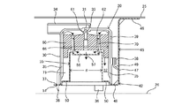
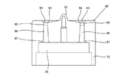
図1、2に燃料流出防止弁の弁体が開と閉の状態を示す全体断面図を示し、図3に燃料流出防止弁の底面図を示し、図4に燃料流出防止弁の背面図を示し、図5〜図7に支持部材を一体成形した固定部材の断面図、底面図および背面図を示し、図8〜図10にフロートの断面図、平面図および底面図を示し、図11および図12にフロートの変形例を示す。本願発明の燃料流出防止弁は、どのような用途に用いられるものでも良いが、以下においては、自動車用の燃料系に用いられるものについて説明する。 1 and 2 are general sectional views showing a state in which the valve body of the fuel outflow prevention valve is open and closed, FIG. 3 is a bottom view of the fuel outflow prevention valve, and FIG. 4 is a rear view of the fuel outflow prevention valve. 5 to 7 show a sectional view, a bottom view, and a rear view of the fixing member integrally formed with the support member, and FIGS. 8 to 10 show a sectional view, a plan view, and a bottom view of the float. FIG. 12 shows a modification of the float. The fuel spill prevention valve of the present invention may be used for any application, but in the following, what is used for a fuel system for automobiles will be described.
燃料流出防止弁20は、ケース30、ケース30内に配置されるフロート60、ケース30を燃料タンク25に固定するフランジ部45および支持部55から形成される固定部材42等からなる。
The fuel
前記ケース30は、下方が開放された略釣鐘状の樹脂製部材であり、その上壁部の中央には、開口31が形成されるとともに、該開口31の下方である内部空間32側には、弁座33が形成される。また、前記開口31の上方には、該開口31を包囲して連通路34がケース30と一体に形成されており、連通路34は、図示しないパイプを介して燃料タンク25外に設けられる図示しないキャニスタに連通される。
The
ケース30内には、内壁面に沿って垂直方向に複数のリブ35が等間隔に設けられており、該リブ35は、ケース30の内壁面とフロート60の側壁面との間に空間を確保し、燃料蒸発ガス等の通路を形成するとともに、その先端部でフロート60の上下動をガイドする。
In the
ケース30の底部には、固定部材42を取り付けるための複数の突起36が垂下される。この突起36は、ケース30の外側面よりやや外方に広がるように傾斜され、その根本部の外周面には後記のフランジ部45の嵌合穴51に係合する溝部37が形成される。また、ケース30の前記連通路34と反対側の側部には、後記のフランジ部45の係止片49が係合する上下に貫通した貫通口を有する係止部材38が形成されるとともに、該係止部材38の上方のケース30の外側面には、図4に示すように2個の燃料蒸発ガス等用の通気孔39が設けられる。
A plurality of
固定部材42は、フランジ部45および支持部55からなる樹脂製或いは金属製の部材であり、フランジ部45および支持部55は一体で形成される。なお、フランジ部45および支持部55は一体のものとして説明するが、別体のものとして形成し一体に組み立てるものでも良い。
The fixing
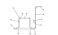
フランジ部45は、図5に断面図、図6に底面図および図7に背面図で示すように、上端水平部46、中間垂直部47および下端水平部48からなり、上端水平部46および中間垂直部47は、矩形状で、下端水平部48は略円形であり、その全体は図1、図5に示すようにクランク状を呈する。
As shown in a sectional view in FIG. 5, a bottom view in FIG. 6, and a rear view in FIG. 7, the
そして、上端水平部46の上面は、燃料タンク25の上面に溶着、接着材等の手段で固着される。中間垂直部47の上端水平部46と反対側の面には、略く字状の係止片49が取り付けられ、固定部材42にケース30を取り付ける際、ケース30の側部に形成される係止部材38の貫通口に該係止片49の先端が挿入され、ケース30を側面から支持する。その結果、ケース30の外側面上方に設けられる図4に示す2個の燃料蒸発ガス等用通気孔39は、中間垂直部47により遮蔽される形態になり、燃料タンク25内の燃料が通気孔39から直接ケース30内に侵入する恐れがなくなる。
The upper surface of the upper
下端水平部48は、略円形で、その中央部に絞り成形等により上方へ突出した筒状の支持部55が形成され、その外周には、燃料タンク25とケース30内とを連通するための複数、図では6個の燃料出入口50が、さらにその外周には、ケース30の底部に垂下される突起36が挿入される複数、図では3個の嵌合穴51がそれぞれ形成される。
The lower end
支持部55は、下端水平部48の中央部を絞り成形等することにより形成した中空筒形状の部材であり、フロート60を支持するための支持部材に相当し、その上面には後記のスプリングの一端を支持するための凹み56が形成され、さらに該窪み56の中央には、燃料タンク25とケース30内とを連通する穴57が設けられる。
The
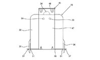
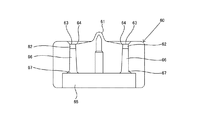
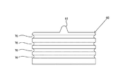
フロート60は、図8に断面図、図9に平面図および図10に底面図で示すように、平面円形、断面略矩形状の樹脂部材である。フロート60の上面中央部には、略山形状の弁体61が形成され、該弁体61の周りには、複数、図では8個の略垂直状の連通口62がフロート60の上下側を連通する形態で形成される。
The
フロート60の上面に弁体61を包囲し、リング状に窪んで最も低い谷部64が形成されされ、連通口62の上端開口部63はこの谷部64に開口される。また、フロート60の底部には、上方に窪んだ底凹部65が形成されるとともに、該底凹部65からさらに上方に窪んだリング状凹陥部66が形成されており、連通口62の下方はこのリング状凹陥部66の上端に開口される。
The
そして、リング状凹陥部66の底凹部65に開口する下端開口部67は、フロート60が前記支持部55上に支持される図1で示す弁体61の開弁時、ケース30の内側面と支持部55の側壁面とで形成されるリング状通路71と遮蔽される位置に開口される。なお、請求項に記載の連通口は、リング状凹陥部66および連通口62が相当するが、リング状凹陥部66がなく、連通口62のみであっても良く、要は、フロート60の上下を連通し、フロート60の上方に侵入した燃料が下方に流下する形態であればどのようなものでも良い。
The
また、フロート60の径Dは、図2に示すように、支持部55の径dより大きくされており、ケース30の内側面と支持部55の側壁面とで形成されるリング状通路71に侵入した燃料は、フロート60の底部面に直接衝突し、フロート60を瞬時に押し上げる。
Further, as shown in FIG. 2, the diameter D of the
燃料流出防止弁20の組み立てについて説明する。まず、ケース30を逆さにし、フロート60を弁体61がケース30の開口31に形成される弁座33に対向する形態でケース30内に挿入する。次いで、コイル状のスプリング70をフロート60内に形成されるリング状凹陥部66に挿入する。このスプリング70の径は、リング状凹陥部66の径と同じにされ、そのばね力により、ケース30内に燃料が侵入したときにフロート60の上動を助ける。
The assembly of the fuel
次いで、固定部材42でケース30の底部を閉蓋する。この際、スプリング70の他端部は、支持部55の上面に形成される凹み56に当接される。そして前記閉蓋は、固定部材42の下端水平部48をケース30の底部に対向させ、下端水平部48の嵌合穴51内にケース30の底部に垂下した突起36を挿入することにより行われる。突起36は、その先端がやや外側に広がる形態であり、突起36にはバネ性を有する。
Next, the bottom of the
そのため、その嵌合穴51内への突起36の嵌合は、力を入れて押し込むことにより行われる。嵌合後は、突起36の外周部に形成される溝部37が嵌合穴51の端部に係合し、両部材の取り付けが完了する。このように、固定部材42とケース30との取り付けは、ワンタッチで行うことができるため、生産性が向上する。なお、嵌合穴51に突起36を嵌合する際、ケース30の側部に設けられる係止部材38とフランジ部45に設けられる係止片49との係合が同時に行われる。
Therefore, the fitting of the
固定部材42とケース30との取り付け後、ケース30を正立させると図1の状態になり、燃料流出防止弁20が完成し、後は、フランジ部45の上端水平部46の上端を燃料タンク25の上部内面に溶着或いは接着材等で取り付けることになる。
After the fixing
ケース30の正立状態では、支持部55の外径dは、ケース30の内径およびフロート60の外径Dより小さいため、ケース30の内壁部と支持部55の側壁面との間にリング状通路71が形成される。
In the upright state of the
次に作用について説明する。通常時、油面26は、図1、図2に示す位置にあり、燃料タンク25内で発生した燃料蒸発ガスは、通気孔39および燃料出入口50より、ケース30内に入り、開口31および連通路34を介してキャニスタに送られる。燃料タンク25が振動し、油面26が燃料出入口50を塞いだとしても、通気孔39はケース30の上方に設けられているため、燃料蒸発ガスの排出は支障なく行われる。
Next, the operation will be described. Normally, the
車両の上下動時や旋回時に油面26が大きく振動し、燃料が燃料出入口50からケース30内に侵入する。侵入した燃料は、リング状通路71からケース30の内壁部とフロート60の側壁面との間を通り、開口31を経て連通路34に流れ込もうとする。
When the vehicle moves up and down or turns, the
しかしながら、ケース30の内壁部と支持部55の側壁面との間で所定の長さを有するリング状通路71が形成されているため、ケース30内に侵入した燃料はこのリング状通路71で増速され、増速された状態で、フロート60の下部の平坦部に衝突する。すると、フロート60は即座に上動し、弁体61は即座に弁座33に当接し、開口31は即座に閉鎖される。そのため、例え、燃料がフロート60の上面に達したとしても、開口31外に流出されることはない。
However, since a ring-shaped
なお、図1に示す弁体61の開弁時では、フロート60の下端開口部67は、支持部55の上面でリング状通路71と遮断されているため、リング状通路71を上方に侵入する燃料は、下端開口部67および連通口62を経てフロート60の上面に至り、弁体61が閉弁される前に開口31外に流出する弊害を防止することができる。
In addition, when the
フロート60の上面に達した燃料は、上面に形成される谷部64に集められ、矢印で示すように連通口62、リング状凹陥部66を介して燃料タンク25内に戻される。また、図1に示す弁体61の開弁時には、連通口62、リング状凹陥部66を介して流下する燃料は、矢印で示すように支持部55の上面に形成される凹み56に集められ、凹み56の中央に形成される穴57より燃料タンク25内に戻される。
The fuel that has reached the upper surface of the
図11にフロート60の変形例を示す。この例のものは、フロート60の下端に円筒状のスカート部75を垂下する形態で形成するものである。燃料タンク25を扁平化するに際し、燃料流出防止弁20、さらにはフロート60も扁平化され、フロート60の高さを高くすることができなくなる。するとフロート60が偏心して上動する等、ケース30内のリブ35に沿ったフロート60の上下動が滑らかに行われなくなる恐れが発生する。
FIG. 11 shows a modification of the
この例のものは、スカート部75によりリブ35に沿うフロート60の側壁面の高さを高くすることができ、上記のような弊害を防止することができる。なお、図11のものは、フロート60とスカート部75を一体成形したものを示すが、両部材を別体に成形し、溶着、接着材等の手段で一体にするものでも良い。また、円筒状のスカート部75は、連続したものでなく断続的な円弧状のようなものでも良い。
In this example, the height of the side wall surface of the
図12にフロート60の他の変形例を示す。この例のものは、フロート60の側壁面に複数のリング状の溝76を形成するものである。このようにすることにより、フロート60の側壁面の表面積が増大し、ケース30内に侵入した燃料によるフロート60を押し上げる力が増大し、さらにはリブ35とフロート側壁面との接触面積が低減するため、フロート60の弁体61が弁座33に当接する時間を短くし、燃料の流出をより確実に防止することができる。この例のものに、図11に示すスカート部75をさらに付加することもできる。なお、リング状の溝76は、連続したリング状でなくても良く、或いは螺旋状のものでも良い。
FIG. 12 shows another modification of the
なお、前記実施例の構成に限定されるものではなく、発明の要旨を逸脱しない範囲において適宜設計変更可能である。 It should be noted that the present invention is not limited to the configuration of the above-described embodiment, and the design can be changed as appropriate without departing from the gist of the invention.
20・・・燃料流出防止弁 25・・・燃料タンク
26・・・油面 30・・・ケース
31・・・開口 32・・・内部空間
33・・・弁座 34・・・連通路
35・・・リブ 36・・・突起
37・・・溝部 38・・・係止部材
39・・・通気孔 42・・・固定部材
45・・・フランジ部 46・・・上端水平部
47・・・中間垂直部 48・・・下端水平部
49・・・係止片 50・・・燃料出入口
51・・・嵌合穴 55・・・支持部
56・・・凹み 57・・・穴
60・・・フロート 61・・・弁体
62・・・連通口 63・・・上端開口部
64・・・谷部 65・・・底凹部
66・・・リング状凹陥部 67・・・下端開口部
70・・・スプリング 71・・・リング状通路
75・・・スカート部 76・・・リング状溝
20 ... Fuel
Claims (8)
Priority Applications (4)
| Application Number | Priority Date | Filing Date | Title |
|---|---|---|---|
| JP2005014313A JP2006200469A (en) | 2005-01-21 | 2005-01-21 | Fuel spill prevention valve |
| CA 2532921 CA2532921A1 (en) | 2005-01-21 | 2006-01-13 | Fuel-effusion prevention valve |
| US11/331,120 US20060162777A1 (en) | 2005-01-21 | 2006-01-13 | Fuel-effusion prevention valve |
| EP20060001148 EP1683672A3 (en) | 2005-01-21 | 2006-01-19 | Fuel-effusion prevention valve |
Applications Claiming Priority (1)
| Application Number | Priority Date | Filing Date | Title |
|---|---|---|---|
| JP2005014313A JP2006200469A (en) | 2005-01-21 | 2005-01-21 | Fuel spill prevention valve |
Publications (1)
| Publication Number | Publication Date |
|---|---|
| JP2006200469A true JP2006200469A (en) | 2006-08-03 |
Family
ID=36190401
Family Applications (1)
| Application Number | Title | Priority Date | Filing Date |
|---|---|---|---|
| JP2005014313A Pending JP2006200469A (en) | 2005-01-21 | 2005-01-21 | Fuel spill prevention valve |
Country Status (4)
| Country | Link |
|---|---|
| US (1) | US20060162777A1 (en) |
| EP (1) | EP1683672A3 (en) |
| JP (1) | JP2006200469A (en) |
| CA (1) | CA2532921A1 (en) |
Cited By (2)
| Publication number | Priority date | Publication date | Assignee | Title |
|---|---|---|---|---|
| JP2019074022A (en) * | 2017-10-16 | 2019-05-16 | 株式会社パイオラックス | Valve device for fuel tank |
| WO2019142464A1 (en) * | 2018-01-19 | 2019-07-25 | 京三電機株式会社 | Fuel tank venting control valve |
Families Citing this family (4)
| Publication number | Priority date | Publication date | Assignee | Title |
|---|---|---|---|---|
| JP2006290085A (en) * | 2005-04-08 | 2006-10-26 | Kyosan Denki Co Ltd | Seal structure of float valve |
| CN103363136B (en) * | 2013-08-02 | 2016-01-20 | 苏州圆能动力科技有限公司 | A kind of external anti-dumping pressure control valve |
| CN104454269A (en) * | 2014-12-04 | 2015-03-25 | 苏州圆能动力科技有限公司 | Steel ball type fuel oil control valve |
| US10843555B2 (en) * | 2018-09-28 | 2020-11-24 | Toyoda Gosei Co., Ltd. | Opening/closing device of fuel tank |
Family Cites Families (9)
| Publication number | Priority date | Publication date | Assignee | Title |
|---|---|---|---|---|
| US2086236A (en) * | 1936-01-17 | 1937-07-06 | Houde Eng Corp | Valving assembly for hydraulic shock absorbers |
| US4413652A (en) * | 1981-03-30 | 1983-11-08 | Oil Air Industries, Inc. | Gas-liquid accumulator |
| FR2636573B1 (en) * | 1988-09-19 | 1990-12-14 | Peugeot | TIMED AERATION DEVICE FOR A FUEL TANK |
| US5605175A (en) * | 1995-05-24 | 1997-02-25 | Bergsma; Rudolph | Fluid responsive vent control valve with peel-away opening action |
| FR2779100B1 (en) * | 1998-05-28 | 2000-08-18 | Journee Paul Sa | MOTOR VEHICLE FUEL TANK RELEASING DEVICE |
| CA2335165C (en) * | 2000-02-11 | 2005-07-12 | Stant Manufacturing Inc. | Weldable mount for fuel system component |
| JP2002147632A (en) | 2000-08-29 | 2002-05-22 | Nifco Inc | Valve device |
| JP3973205B2 (en) * | 2002-08-07 | 2007-09-12 | 株式会社ニフコ | Fuel shut-off valve device |
| JP3953916B2 (en) * | 2002-08-23 | 2007-08-08 | 豊田合成株式会社 | Fuel tank fuel spill regulating device |
-
2005
- 2005-01-21 JP JP2005014313A patent/JP2006200469A/en active Pending
-
2006
- 2006-01-13 CA CA 2532921 patent/CA2532921A1/en not_active Abandoned
- 2006-01-13 US US11/331,120 patent/US20060162777A1/en not_active Abandoned
- 2006-01-19 EP EP20060001148 patent/EP1683672A3/en not_active Withdrawn
Cited By (3)
| Publication number | Priority date | Publication date | Assignee | Title |
|---|---|---|---|---|
| JP2019074022A (en) * | 2017-10-16 | 2019-05-16 | 株式会社パイオラックス | Valve device for fuel tank |
| JP7010651B2 (en) | 2017-10-16 | 2022-01-26 | 株式会社パイオラックス | Fuel tank valve device |
| WO2019142464A1 (en) * | 2018-01-19 | 2019-07-25 | 京三電機株式会社 | Fuel tank venting control valve |
Also Published As
| Publication number | Publication date |
|---|---|
| EP1683672A2 (en) | 2006-07-26 |
| EP1683672A3 (en) | 2008-01-09 |
| US20060162777A1 (en) | 2006-07-27 |
| CA2532921A1 (en) | 2006-07-21 |
Similar Documents
| Publication | Publication Date | Title |
|---|---|---|
| KR101409052B1 (en) | Fuel tank valve device | |
| JP2006200469A (en) | Fuel spill prevention valve | |
| JP6295905B2 (en) | Fuel shut-off valve | |
| US20090211649A1 (en) | Fuel cutoff valve | |
| US7963296B2 (en) | Fuel cutoff valve | |
| JP5005330B2 (en) | Fuel spill prevention valve | |
| JP6157376B2 (en) | Valve device | |
| US10279679B2 (en) | Valve device | |
| EP3141784B1 (en) | Valve device | |
| JP2006290085A (en) | Seal structure of float valve | |
| JP5949686B2 (en) | In-tank valve unit | |
| JP5123837B2 (en) | Float valve device | |
| CN105711408A (en) | Valve apparatus for fuel tank | |
| JP5660070B2 (en) | Fuel shut-off valve | |
| US20050133089A1 (en) | Evaporative gas control valve structure | |
| US5954083A (en) | Liquid flow-out prevention valve | |
| JP2010105523A (en) | Fuel shut-off valve | |
| JP5461087B2 (en) | Fuel shut-off valve | |
| JP6020661B2 (en) | Full tank control valve device | |
| WO2012118118A1 (en) | Fuel shutoff valve | |
| JP4536611B2 (en) | Float valve opening structure with single seal structure | |
| JPH08291875A (en) | Structure for stop valve | |
| JP4207875B2 (en) | Fuel shut-off valve | |
| JP4487915B2 (en) | Fuel shut-off valve | |
| JP2007127017A (en) | Fuel leakage prevention valve |
Legal Events
| Date | Code | Title | Description |
|---|---|---|---|
| A521 | Written amendment |
Free format text: JAPANESE INTERMEDIATE CODE: A523 Effective date: 20060607 |
|
| A711 | Notification of change in applicant |
Free format text: JAPANESE INTERMEDIATE CODE: A711 Effective date: 20060607 |
|
| A521 | Written amendment |
Free format text: JAPANESE INTERMEDIATE CODE: A821 Effective date: 20060607 |
|
| A521 | Written amendment |
Free format text: JAPANESE INTERMEDIATE CODE: A523 Effective date: 20060719 |
|
| A621 | Written request for application examination |
Free format text: JAPANESE INTERMEDIATE CODE: A621 Effective date: 20070927 |
|
| A977 | Report on retrieval |
Free format text: JAPANESE INTERMEDIATE CODE: A971007 Effective date: 20090729 |
|
| A131 | Notification of reasons for refusal |
Free format text: JAPANESE INTERMEDIATE CODE: A131 Effective date: 20090804 |
|
| A02 | Decision of refusal |
Free format text: JAPANESE INTERMEDIATE CODE: A02 Effective date: 20100112 |