EP1682046B1 - Multizonale monofokale intraokularlinse zur korrektur von optischen abweichungen - Google Patents
Multizonale monofokale intraokularlinse zur korrektur von optischen abweichungen Download PDFInfo
- Publication number
- EP1682046B1 EP1682046B1 EP04800995A EP04800995A EP1682046B1 EP 1682046 B1 EP1682046 B1 EP 1682046B1 EP 04800995 A EP04800995 A EP 04800995A EP 04800995 A EP04800995 A EP 04800995A EP 1682046 B1 EP1682046 B1 EP 1682046B1
- Authority
- EP
- European Patent Office
- Prior art keywords
- lens
- zone
- zonal
- optical
- ophthalmic lens
- Prior art date
- Legal status (The legal status is an assumption and is not a legal conclusion. Google has not performed a legal analysis and makes no representation as to the accuracy of the status listed.)
- Active
Links
- 230000003287 optical effect Effects 0.000 title claims description 85
- 230000004075 alteration Effects 0.000 title claims description 54
- 208000036829 Device dislocation Diseases 0.000 claims 3
- 230000007704 transition Effects 0.000 abstract description 4
- 210000000695 crystalline len Anatomy 0.000 description 99
- 210000001508 eye Anatomy 0.000 description 63
- 238000013461 design Methods 0.000 description 47
- 210000001525 retina Anatomy 0.000 description 28
- 210000004087 cornea Anatomy 0.000 description 24
- 238000000034 method Methods 0.000 description 19
- 210000001747 pupil Anatomy 0.000 description 16
- 230000002093 peripheral effect Effects 0.000 description 9
- 230000035945 sensitivity Effects 0.000 description 7
- 230000000007 visual effect Effects 0.000 description 6
- 238000012937 correction Methods 0.000 description 5
- 238000002513 implantation Methods 0.000 description 5
- 239000000463 material Substances 0.000 description 5
- 208000002177 Cataract Diseases 0.000 description 4
- 206010010071 Coma Diseases 0.000 description 4
- 230000004438 eyesight Effects 0.000 description 4
- 238000012546 transfer Methods 0.000 description 4
- 206010027646 Miosis Diseases 0.000 description 3
- 230000003466 anti-cipated effect Effects 0.000 description 3
- 239000002775 capsule Substances 0.000 description 3
- 230000000694 effects Effects 0.000 description 3
- 239000007943 implant Substances 0.000 description 3
- 230000006872 improvement Effects 0.000 description 3
- 238000004088 simulation Methods 0.000 description 3
- 238000001356 surgical procedure Methods 0.000 description 3
- 230000004304 visual acuity Effects 0.000 description 3
- 230000001594 aberrant effect Effects 0.000 description 2
- 238000013459 approach Methods 0.000 description 2
- 201000009310 astigmatism Diseases 0.000 description 2
- 230000004323 axial length Effects 0.000 description 2
- 230000008901 benefit Effects 0.000 description 2
- 230000004305 hyperopia Effects 0.000 description 2
- 201000006318 hyperopia Diseases 0.000 description 2
- 238000005259 measurement Methods 0.000 description 2
- 208000001491 myopia Diseases 0.000 description 2
- 229920003229 poly(methyl methacrylate) Polymers 0.000 description 2
- 239000004926 polymethyl methacrylate Substances 0.000 description 2
- 208000014733 refractive error Diseases 0.000 description 2
- 230000004256 retinal image Effects 0.000 description 2
- 238000012876 topography Methods 0.000 description 2
- 238000013519 translation Methods 0.000 description 2
- 241001481828 Glyptocephalus cynoglossus Species 0.000 description 1
- 206010020675 Hypermetropia Diseases 0.000 description 1
- 238000000342 Monte Carlo simulation Methods 0.000 description 1
- 241000204801 Muraenidae Species 0.000 description 1
- NIXOWILDQLNWCW-UHFFFAOYSA-N acrylic acid group Chemical group C(C=C)(=O)O NIXOWILDQLNWCW-UHFFFAOYSA-N 0.000 description 1
- 230000032683 aging Effects 0.000 description 1
- 210000002159 anterior chamber Anatomy 0.000 description 1
- 230000001419 dependent effect Effects 0.000 description 1
- 238000011161 development Methods 0.000 description 1
- 230000018109 developmental process Effects 0.000 description 1
- 238000011156 evaluation Methods 0.000 description 1
- 210000000887 face Anatomy 0.000 description 1
- 230000003993 interaction Effects 0.000 description 1
- 239000007788 liquid Substances 0.000 description 1
- 238000004519 manufacturing process Methods 0.000 description 1
- 230000004379 myopia Effects 0.000 description 1
- 229920001296 polysiloxane Polymers 0.000 description 1
- 230000008569 process Effects 0.000 description 1
- 238000012545 processing Methods 0.000 description 1
- 230000009467 reduction Effects 0.000 description 1
- 229910052710 silicon Inorganic materials 0.000 description 1
- 239000010703 silicon Substances 0.000 description 1
- 230000007480 spreading Effects 0.000 description 1
- 239000000126 substance Substances 0.000 description 1
- 239000013589 supplement Substances 0.000 description 1
- 238000012360 testing method Methods 0.000 description 1
Images


Classifications
-
- A—HUMAN NECESSITIES
- A61—MEDICAL OR VETERINARY SCIENCE; HYGIENE
- A61F—FILTERS IMPLANTABLE INTO BLOOD VESSELS; PROSTHESES; DEVICES PROVIDING PATENCY TO, OR PREVENTING COLLAPSING OF, TUBULAR STRUCTURES OF THE BODY, e.g. STENTS; ORTHOPAEDIC, NURSING OR CONTRACEPTIVE DEVICES; FOMENTATION; TREATMENT OR PROTECTION OF EYES OR EARS; BANDAGES, DRESSINGS OR ABSORBENT PADS; FIRST-AID KITS
- A61F2/00—Filters implantable into blood vessels; Prostheses, i.e. artificial substitutes or replacements for parts of the body; Appliances for connecting them with the body; Devices providing patency to, or preventing collapsing of, tubular structures of the body, e.g. stents
- A61F2/02—Prostheses implantable into the body
- A61F2/14—Eye parts, e.g. lenses, corneal implants; Implanting instruments specially adapted therefor; Artificial eyes
- A61F2/16—Intraocular lenses
- A61F2/1613—Intraocular lenses having special lens configurations, e.g. multipart lenses; having particular optical properties, e.g. pseudo-accommodative lenses, lenses having aberration corrections, diffractive lenses, lenses for variably absorbing electromagnetic radiation, lenses having variable focus
- A61F2/1616—Pseudo-accommodative, e.g. multifocal or enabling monovision
- A61F2/1618—Multifocal lenses
-
- A—HUMAN NECESSITIES
- A61—MEDICAL OR VETERINARY SCIENCE; HYGIENE
- A61F—FILTERS IMPLANTABLE INTO BLOOD VESSELS; PROSTHESES; DEVICES PROVIDING PATENCY TO, OR PREVENTING COLLAPSING OF, TUBULAR STRUCTURES OF THE BODY, e.g. STENTS; ORTHOPAEDIC, NURSING OR CONTRACEPTIVE DEVICES; FOMENTATION; TREATMENT OR PROTECTION OF EYES OR EARS; BANDAGES, DRESSINGS OR ABSORBENT PADS; FIRST-AID KITS
- A61F2/00—Filters implantable into blood vessels; Prostheses, i.e. artificial substitutes or replacements for parts of the body; Appliances for connecting them with the body; Devices providing patency to, or preventing collapsing of, tubular structures of the body, e.g. stents
- A61F2/02—Prostheses implantable into the body
- A61F2/14—Eye parts, e.g. lenses, corneal implants; Implanting instruments specially adapted therefor; Artificial eyes
- A61F2/16—Intraocular lenses
- A61F2/1613—Intraocular lenses having special lens configurations, e.g. multipart lenses; having particular optical properties, e.g. pseudo-accommodative lenses, lenses having aberration corrections, diffractive lenses, lenses for variably absorbing electromagnetic radiation, lenses having variable focus
- A61F2/1616—Pseudo-accommodative, e.g. multifocal or enabling monovision
-
- A—HUMAN NECESSITIES
- A61—MEDICAL OR VETERINARY SCIENCE; HYGIENE
- A61F—FILTERS IMPLANTABLE INTO BLOOD VESSELS; PROSTHESES; DEVICES PROVIDING PATENCY TO, OR PREVENTING COLLAPSING OF, TUBULAR STRUCTURES OF THE BODY, e.g. STENTS; ORTHOPAEDIC, NURSING OR CONTRACEPTIVE DEVICES; FOMENTATION; TREATMENT OR PROTECTION OF EYES OR EARS; BANDAGES, DRESSINGS OR ABSORBENT PADS; FIRST-AID KITS
- A61F2/00—Filters implantable into blood vessels; Prostheses, i.e. artificial substitutes or replacements for parts of the body; Appliances for connecting them with the body; Devices providing patency to, or preventing collapsing of, tubular structures of the body, e.g. stents
- A61F2/02—Prostheses implantable into the body
- A61F2/14—Eye parts, e.g. lenses, corneal implants; Implanting instruments specially adapted therefor; Artificial eyes
- A61F2/16—Intraocular lenses
- A61F2/1613—Intraocular lenses having special lens configurations, e.g. multipart lenses; having particular optical properties, e.g. pseudo-accommodative lenses, lenses having aberration corrections, diffractive lenses, lenses for variably absorbing electromagnetic radiation, lenses having variable focus
- A61F2/1637—Correcting aberrations caused by inhomogeneities; correcting intrinsic aberrations, e.g. of the cornea, of the surface of the natural lens, aspheric, cylindrical, toric lenses
-
- A—HUMAN NECESSITIES
- A61—MEDICAL OR VETERINARY SCIENCE; HYGIENE
- A61F—FILTERS IMPLANTABLE INTO BLOOD VESSELS; PROSTHESES; DEVICES PROVIDING PATENCY TO, OR PREVENTING COLLAPSING OF, TUBULAR STRUCTURES OF THE BODY, e.g. STENTS; ORTHOPAEDIC, NURSING OR CONTRACEPTIVE DEVICES; FOMENTATION; TREATMENT OR PROTECTION OF EYES OR EARS; BANDAGES, DRESSINGS OR ABSORBENT PADS; FIRST-AID KITS
- A61F2240/00—Manufacturing or designing of prostheses classified in groups A61F2/00 - A61F2/26 or A61F2/82 or A61F9/00 or A61F11/00 or subgroups thereof
- A61F2240/001—Designing or manufacturing processes
- A61F2240/002—Designing or making customized prostheses
-
- A—HUMAN NECESSITIES
- A61—MEDICAL OR VETERINARY SCIENCE; HYGIENE
- A61F—FILTERS IMPLANTABLE INTO BLOOD VESSELS; PROSTHESES; DEVICES PROVIDING PATENCY TO, OR PREVENTING COLLAPSING OF, TUBULAR STRUCTURES OF THE BODY, e.g. STENTS; ORTHOPAEDIC, NURSING OR CONTRACEPTIVE DEVICES; FOMENTATION; TREATMENT OR PROTECTION OF EYES OR EARS; BANDAGES, DRESSINGS OR ABSORBENT PADS; FIRST-AID KITS
- A61F2250/00—Special features of prostheses classified in groups A61F2/00 - A61F2/26 or A61F2/82 or A61F9/00 or A61F11/00 or subgroups thereof
- A61F2250/0014—Special features of prostheses classified in groups A61F2/00 - A61F2/26 or A61F2/82 or A61F9/00 or A61F11/00 or subgroups thereof having different values of a given property or geometrical feature, e.g. mechanical property or material property, at different locations within the same prosthesis
- A61F2250/0053—Special features of prostheses classified in groups A61F2/00 - A61F2/26 or A61F2/82 or A61F9/00 or A61F11/00 or subgroups thereof having different values of a given property or geometrical feature, e.g. mechanical property or material property, at different locations within the same prosthesis differing in optical properties
Definitions
- This invention relates to intraocular lenses (IOLs) and, more particularly, to multi-zonal monofocal IOLs that correct optical aberrations for a variety of human eyes with different corneas under a wide range of lighting conditions and that are effective even when decentered or tilted.
- IOLs intraocular lenses
- multi-zonal monofocal IOLs that correct optical aberrations for a variety of human eyes with different corneas under a wide range of lighting conditions and that are effective even when decentered or tilted.
- an incoming beam of light is focused through the cornea and through the crystalline lens in a way that causes all of the light from a point source to converge at the same spot on the retina of the eye, ideally on the fovea area of the retina. This convergence occurs because all of the optical path lengths, for all light in the beam, are equal to each other. Stated differently, in the perfect eye the time for all light to transit through the eye will be the same regardless of the particular path that is taken by the light.
- coma exists when an asymmetry in the optical system causes unequal optical path lengths in a preferred direction.
- the image of an off-axis point object takes on a comet-like shape.
- spherical aberration exists when rays at different radial heights from the optical axis focus at different axial locations near the retina.
- coma exists only in asymmetric systems
- spherical aberration can exist in both symmetric and asymmetric systems.
- studies have show that spherical aberration is one of the strongest higher order aberrations in the human visual system.
- the retinal image may be improved if the spherical aberration is corrected according to known techniques.
- An intraocular lens is commonly used to replace the natural lens of a human eye when warranted by medical conditions such as cataracts.
- cataract surgery the surgeon removes the natural crystalline lens from the capsular bag or posterior capsule and replaces it with an IOL.
- IOLs may also be implanted in an eye (e.g., in the anterior chamber) with no cataract to supplement the refractive power of the natural crystalline lens, correcting large refractive errors.
- IOLs monofocal, or fixed focal length, lenses that primarily correct refractive error.
- Most monofocal IOLs are designed with spherical anterior and posterior surfaces.
- the spherical surfaces of the typically positive power IOLs cause positive spherical aberration, inter alia.
- replacement of the crystalline lens with a typical monofocal IOL leaves the eye with positive spherical aberration.
- the eye following cataract surgery is left a with finite number of complex lower and higher order aberrations, limiting the image quality on the retina.
- a typical approach for improving the vision of a patient has been to first obtain measurements of the eye that relate to the topography of the anterior surface of the cornea. Specifically, the topography measurements yield a mathematical description of the anterior surface of the cornea. This corneal surface is placed in a theoretical model of the patient's eye with an IOL replacing the crystalline lens. Ray-tracing techniques are employed to find the IOL design which corrects for the spherical aberration of the cornea. Ideally, if implanted with this custom IOL, the patient's vision will improve.
- TECNIS Zero-Colorine-Coupled Inocular
- the TECNIS lens has a prolate anterior surface, which is intended to reduce spherical aberrations of the cornea.
- This lens may be designed using methods described in U.. S. Patent Number 6,609,793 and PCT publication WO 01/89424, both to Norrby, et al.
- the methods in these publications involve characterizing aberrant corneal surfaces as linear combinations of Zernike polynomials, and then modeling or selecting an intraocular lens which, in combination with a characteristic corneal surface, reduces the optical aberrations ocular system.
- the lenses resulting from these methods may be continuous aspherical surfaces across the entire optical zone and may be used to reduce spherical aberration of the eye by introducing negative spherical aberration to counter the typically positive spherical aberration of the cornea. In these lenses, there may be a single base curve on which the aspheric surface is superimposed.
- the Technics IOL has been found to be to improve visual contrast sensitivity at a frequency up to 18 cycles/degree.
- the TECNIS brand of lens generally requires precise positioning in the capsular bag to provide improved optical quality over a spherical IOL (c.f., " Prospective Randomized Trial of an Anterior Surface Modified Prolate Intraocular Lens," Journal of Refractive pressurey, Vo. 18, Nov/Dec 2002 ). Slight errors in decentration (radial translation) or tilt (axial rotation) greatly reduces the effectiveness of the lens, especially in low-light conditions, thus making the task of the surgeon more difficult. Furthermore, shrinkage of the capsular bag or other post-implantation anatomical changes can affect the alignment or tilt of the lens along the eye's optical axis.
- the "typical" magnitude of decentration resulting from the implantation of an intraocular lens in an average case, and factoring in post-implantation movement is less than about 1.0 mm, and usually less than about 0.5 mm.
- decentration of an IOL greater than about 0.15 to approximately mm is clinically relevant (i.e., noticeably affects the performance of the optical system, according to those skilled in the art).
- the "typical" magnitude of tilt resulting from the implantation of an intraocular lens in an average case, and factoring in post-implantation movement is less than about 10 degrees, and usually less than about 5 degrees. Therefore, in practice, the benefits of the TECNIS brand of lens may be offset by its apparent drawbacks in the real world.
- US 6,126,286 A describes a lens according to the preamble of claim 1.
- the present invention provides a multi-zonal monofocal ophthalmic lens that is less sensitive to its disposition in the eye by reducing aberrations, including the spherical aberration, over a range of decentration.
- the monofocal ophthalmic lenses of the present invention may also be configured to perform well across eyes with different corneal aberrations (e.g., different asphericities). They comprise the features of claim 1.
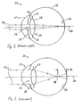
- Figure 1 is a schematic vertical cross-section of the human eye in a bright light environment and showing a pair of light rays passing through the optical system of the cornea and an implanted intraocular lens of the prior art to focus on the retina.
- Figure 2 is a schematic vertical cross-section of the human eye in a low light environment and showing a pair of light rays passing through the optical system of the cornea and the peripheral regions of an implanted intraocular lens of the prior art to focus in front of the retina.
- Figure 3 is a schematic vertical cross-section of the human eye in a bright light environment and showing a pair of light rays passing through the optical system of the cornea and a decentered implanted intraocular lens of the prior art to focus on the retina.
- Figure 4 is a schematic vertical cross-section of the human eye in a medium light environment and showing a pair of light rays passing through the optical system of the cornea and a decentered implanted intraocular lens of the prior art to focus in front of the retina.
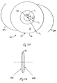
- Figures 5A and 5B are schematic plan and side views of a monofocal intraocular lens of the present invention illustrating concentric zones about an optical axis.
- Figures 6A and 6B show simulated modulation transfer functions for an aspheric, spherical and multi-zonal monofocal IOLs at a 5 mm pupil diameter with no decentration and 0.5 mm decentration, respectively.
- Figure 7 show simulated aspheric, spherical, and multi-zonal monofocal IOL MTF curves at a 5 mm pupil diameter representing the respective average MTFs over 100 eyes varying in corneal aberrations, IOL decentration and tilt, and small pupil size changes.
- the present invention encompasses an intraocular lens (IOL) design that reduces sensitivity to decentration within the eye while maintaining superior Module Transfer Function (MTF) performance for large pupils.
- the MTF is a measure of visual performance that can be plotted on a non-dimensional scale from a minimum of 0.0 to a maximum of 1.0 across a range of spatial frequencies in units of cycles per mm.
- the MTF is a measure of the efficiency of "transferring" the contrast of an object into an image.
- the spatial frequency is inversely proportional to the size of the object. Thus, small objects at the limit of visual resolution have high spatial frequencies than larger objects.
- the IOL described herein comprises a multi-zonal monofocal lens in which the anterior lens surface, posterior lens surface, or both comprises a plurality of zones that operate together on an incident wavefront to produce a corrected ocular image.
- the different zones of the IOL of the present invention generally have different mean spherical curvatures and/or Diopter powers, but the Diopter power differences between zones are far less than the typical 2 Diopter to 4 Diopter design differences associated with multi-focal IOLs.
- the maximum Diopter power difference between any two zones is less than at least about 0.75 D, advantageously less than about 0.65 D.
- the term "monofocal lens” is considered to be a lens in which light entering the lens from a distant point source is focused to substantially a single point.
- light from a distant point source entering the lens zones substantially fall within the range of the depth-of-focus of a spherical lens having an equivalent focal length.
- optical power and “Diopter power” refer to the effective optical or Diopter power of a zone when the lens is part of an ocular lens system such as, for example, a cornea, a multi-zonal monofocal IOL, a retina, and the material surrounding these components.
- This definition may include the effects of the vergence or angle of light rays intersecting the IOL surface caused by the power of the cornea. This may include the total vergence from all optical surfaces in front of the multi-zonal monofocal IOL.
- an algorithm for calculating the Diopter power may begin with a ray-tracing a model of the human eye incorporating a multi-zonal monofocal IOL. At a particular radial location on the IOL surface, Snell's law may be applied to calculate the angle of the light ray following the refraction. The optical path length of the distance between a point on the surface and the optical axis (axis of symmetry) may be used to define the local radius of curvature of the local wavefront. Using such an approach, the Diopter power is equal to the difference in indicies of refraction divided by this local radius of curvature.
- IOLs of the present invention are designed to outperform certain IOLs of the prior art in low or moderate light situations over a larger range of implant positions.
- clinicians recognize that in the average case intraocular lenses implanted in the posterior capsule end up decentered from the optical axis of the host eye by between about 0.15-0.4 mm.
- the decentration is greater as a result of poor implant technique or non-axisymmetric forces imparted by the host eye. Indeed, decentration of more than 0.5 mm, and sometimes up to 1.0 mm is experienced.
- IOLs of the present invention are specifically designed to exhibit superior performance in comparison to the prior art IOLs when decentered by at least about 0.15 mm and in particular in low or moderate light conditions.
- IOLs of the present invention are designed to exhibit superior performance in comparison to prior art IOLs when decentered by greater than about 0.5 mm or greater than about 1.0 mm.
- the amount of decentering to be accommodated depends upon design constraints such as, for example, the accuracy of the surgical method to be used for implanting the IOL. Since the multi-zonal monofocal IOLs provide improved performance for decentered conditions, it is anticipated that patients will generally experience greater satisfaction with a multi-zonal monofocal IOL than with other prior art IOLs.
- Figure 1 is a schematic vertical cross-section through a human eye 20 having an IOL 22 of the prior art implanted therein.
- the optical system of the eye 20 includes an outer cornea 24, a pupil 26 defined by an orifice of an iris 28, the IOL 22, and a retina 30 formed on the posterior inner surface of the ocular globe 32.
- anterior and posterior are used in their conventional sense; anterior refers to the front side of the eye close to the cornea, while posterior refers to the rear side close to the retina.
- the eye defines a natural optical axis OA.
- the drawing shows the eye 20 in a bright light environment with the iris 28 constricted resulting in a relatively small pupil 26.
- the exemplary IOL 22 is adapted to be centered along the optical axis OA and within a capsular bag (not shown) just posterior to the iris 28.
- the IOL 22 may be provided with haptics or fixation members 34.
- An optic of the IOL 22 is defined by an anterior face 36 and posterior face 38.
- the optic may take a variety of configurations known in the art, such as the convex-convex configuration illustrated in Figure 5B . It should be understood that the present invention is not limited to posterior capsule-implanted IOLs.
- a pair of light rays 40 pass through cornea 24, pupil 26, the IOL 22.
- the rays 40 then focus on the retina 30 along the optical axis OA.
- the light rays 40 pass through the mid-portion of the lens optic.
- the intraocular lenses of the prior art are relatively effective in focusing such light rays at a point on the retina 30 along the optical axis OA.
- Figure 2 shows the eye 20 having the' IOL 22 therein in a low light environment.
- the iris 28 opens up creating a relatively large pupil 26 and permitting more light to strike the IOL 22.
- a pair of light rays 42 passing through the peripheral regions of the pupil 26 may be incorrectly refracted by the peripheral regions of the optic of the IOL 22 in the manner shown. That is, the light rays 42 focus on a spot 44 along the optical axis OA that is in front of the retina 30 by a distance 46.
- Such refraction is termed positive spherical aberration because the light rays 42 focus in front of the retina 30.
- a negative spherical aberration focuses light rays at the imaginary point along the optical axis OA behind the retina 30.
- Such aberrations can also occur in an eye with the natural lens still in place.
- the crystalline lens in the aging eye may not refract light properly under low light environments. The practical result of such a condition may be a loss in image quality.
- Figure 3 illustrates the human eye 20 in a bright light environment such as shown in Figure 1 .
- the IOL 22 centered along the optical axis OA is again shown in solid line, but is also shown in dashed line 22' representing a condition of decentration.
- decentration involves a radial translation of the intraocular lens from a centered configuration on the natural optical axis OA.
- the light rays 40 pass through the cornea 24 and relatively small pupil 26, and are refracted through the central region of the decentered intraocular lens optic 22'. That is, despite the undesirable decentration, the optic 22' performs well in bright light environments because light does not strike and refract through its peripheral regions.
- Figure 4 illustrates the eye 20 in a medium light environment, in which the iris 28 is somewhat larger compared to the condition shown in Figure 3 , but is not fully expanded as seen in the low light environment of Figure 2 .
- a centered IOL 22 would likely perform adequately, but the decentered lens 22' will not. More particularly, a light ray 48 passing close to the iris 28 will strike and be incorrectly refracted through a peripheral region of the decentered optic 22' as shown.
- Intraocular lenses of the prior art have varying degrees of sensitivity to decentration, and the situation shown in Figure 4 is for illustration purposes only and does not represent any particular lens.
- lenses designed to correct for spherical aberration are relatively sensitive to small magnitudes of decentration.
- Such lenses have a complex refractive surface that changes relatively continuously across whichever face it is formed (i.e., anterior or posterior). This continuous refractive surface provides a negative correction for the positive spherical aberration on the cornea, but when the lens is decentered the closely calculated balance between the two optical devices may be lost. Indeed, other optical aberrations such as coma and astigmatism may be created by the resulting mismatch.
- FIGs 5A and 5B schematically illustrate in plan and side views a monofocal IOL 60 of the present invention having an optic 62 and a pair of haptics or fixation members 64a, 64b extending outward therefrom.
- the optic 62 has a generally circular peripheral edge 66 and a plurality of concentric annular refractive bands or zones formed thereon.
- the peripheral edge 66 is desirably an axially oriented edge with thickness, as seen in Figure 5B , although curved or angled edge surfaces, or combinations thereof, are possible.
- the optic 62 has an anterior face 68a and an opposite posterior face 68b separated by the peripheral edge 66.
- the refractive zones can be formed on either the anterior or posterior face, or in some cases as a combination of both faces.
- a central and inner zone 70 centered on the optical axis OA extends outward to a radius of r 1
- at least one intermediate zone 72 surrounds the inner zone 70 and extends outward to a radius of r 2
- an outer zone 74 surrounds the intermediate zone 72 and extends therefrom to the outer periphery 66 of the optic 62 and a radius of r 3 .
- r 1 is between about 1-1.5 mm
- r 2 is between about 1.5-2.2 mm
- r 3 is about 3 mm. More desirably, r 1 is about 1.4 mm and r 2 is about 2.0 mm. In certain instances, it may be desirable that r 3 is greater than 3 mm, for instance in order to preclude undesired edge effects.
- the inner zone 70, intermediate zone 72, and outer zone 74 may have surfaces that are either spherical or aspherical in shape.
- the intermediate zone 72 may comprise a combination of annular zones, although a single annular zone is generally desirable.
- the inner zone 70 is spherical
- the intermediate zone 72 is aspherical
- the outer zone 74 is also aspherical.
- the power of the inner zone 70 dominates the visual performance of the eye when the pupil is small, such as in bright daylight situations.
- the intermediate zone 72 is at least designed to help correct aberrations of the IOL when it is decentered, tilted, or otherwise in a non-optimal state.
- the power of intermediate zone 72 is extremely close to that of the' inner zone 70.
- the outer zone 74 may be aspherical and designed to minimize the spherical aberrations natural to spherical monofocal IOLs.
- the intermediate zone 72 has a correction power that is less than the correction power of the inner zone 70.
- the intermediate zone 72 of the multi-zonal monofocal IOL 60 is used to reduce surface power, redirecting the light ray 48 to the focal point on the retina.
- the intermediate zone 72 may also provide correction in cases of tilting of the lens within the typical range of at least about 1 to 10 degrees, depending upon design constraints such as, for example, the accuracy of the surgical method to be used for implanting the IOL.
- the IOL 60 is considered to be a monofocal lens because the relative refractive powers of the zones 70, 72, and 74 are close to one another and within the range of the depth-of-focus of typical spherical monofocal IOLs.
- a "monofocal" lens is one in which discrete adjacent regions or zones have a maximum difference in refractive power of less than at least about 0.75 Diopter.
- the refractive power of any one zone may be interpreted as the mean power within that zone. It should also be understood that discrete adjacent zones does not necessarily mean that there is a sharp physical transition therebetween, rather the manufacturing process may be designed to generally provide a smooth transition between adjacent zones.
- the IOL 60 may be fabricated from materials used in the art, such as silicon, acrylic, or Polymethylmethacrylate (PMMA), or any other material that is suitable for use in or on a human eye. Materials may also be selected so as to provide a desired optical performance. For instance, the refractive index is known to vary with different materials and may, therefore, be used as a design parameter for attaining a desired optical performance or affect from the IOL 60.
- materials used in the art such as silicon, acrylic, or Polymethylmethacrylate (PMMA), or any other material that is suitable for use in or on a human eye. Materials may also be selected so as to provide a desired optical performance. For instance, the refractive index is known to vary with different materials and may, therefore, be used as a design parameter for attaining a desired optical performance or affect from the IOL 60.
- PMMA Polymethylmethacrylate
- the IOL 60 may also be used in conjunction with other optical devices such as diffractive optical elements (DOE).
- DOE diffractive optical elements
- the anterior lens surface of the IOL 60 may comprise a multi-zonal surface and the posterior lens surface may contain a DOE such as a diffractive grating, or visa versa.
- the multi-zonal surface itself may comprise a DOE such as a diffractive grating.
- the DOE may also be used, for example, to correct for chromatic aberrations or to improve the performance of the IOL 60 when displaced from the optimal position (e.g., centered and normal to the optical axis).
- the DOE is disposed over only a portion of the one of the IOL surfaces.
- the DOE may be disposed over the intermediate zone 72 and used as an additional parameter for improving the performance of the IOL 60.
- the IOL 60 may be designed to have a nominal optical power suited for the particular environment in which it is to be used. It is anticipated that the nominal optical power of the IOL 60 will generally be within a range of about -20 Diopters to at least about +35 Diopters. Desirably, the optical power of the IOL 60 is between about 10 Diopters to at least about 30 Diopter. In certain applications, the optical power of the IOL 60 is approximately 20 Diopters, which is a typical optical power for the natural crystalline lens in a human eye.
- the inventors have discovered that spherical aberration can be reduced for both on-design and off-design conditions by forming a lens surface to have a multi-zonal structure, with each zone having different surface parameters, for example, the base radius of curvature.
- the surface sag of the IOL 60 i.e. multi-zonal surface contour
- the surface sag of the IOL 60 may be determined using an equation that changes across the lens.
- the Bjs and Tjs are optional boundary parameters that can be used to connect the zonal surfaces smoothly.
- the variable M is an integer that determines how smoothly one zone transitions to another.
- the asphericity constant K 1 in the inner zone 70 is preferably zero (i.e., the inner zone 70 comprises a spherical surface).
- the base radius of curvature C 1 in the inner zone 70 is considered to be the base surface power of the lens.
- a preferred range of the number of zones is between at least about 3-7, more preferably between 3-5; however, larger numbers of zones may be used of particular design conditions.
- the parameters in the outlying zones can be optimally determined such that each zonal surface refracts more of the light rays in that particular zone to the focus set by the inner zone. This process can be achieved by the aid of a commercial optical ray tracing design software, such as ZEMAX optical design program from ZEMAX Development Corporation (4901 Morena Blvd. Suite 207, San Diego, CA, 92117-7320).
- the base curves in at least two zones are different (preferably the inner and intermediate zones), though all zones may have different base curves.
- the anterior surface has three zones, each having a different base radius of curvature.
- the posterior surface is a one zone spherical surface.
- Table 1 provides an example of a multi-zonal monofocal IOL consistent witch the present invention.
- Figures 6A and 6B illustrate the IOL performance the multi-zonal monofocal lens shown in Table 1 in terms of the simulated modulation transfer functions as compared to both a spherical lens and an aspheric lens (the TECNIS brand of lens). These simulated results are based on a 5 mm pupil diameter with no decentration ( Figure 6A ) and 0.5 mm decentration ( Figure 6B).
- Figure 6A illustrates the performance for each type of lens when the lenses are precisely centered within the eye.
- Figure 6B the performance of each type of lens is illustrated when the lens is decentered from the optical axis of the eye by 0.5 mm, a condition that is not uncommon under realistic conditions.
- the price paid for the reduction in non-nominal sensitivity is the slightly lower multi-zonal design MTF compared to the aspheric MTF shown in Figure 6A .
- the multi-zonal MTF remains significantly improved compared to the spherical design MTF.
- Figure 7 Illustrates the results of a Monte Carlo simulation in the form of plots of the average MTF performance for aspherical, aspheric, and multi-zonal monofocale lolls based on over 100 different eyes and under Varying conditions of corneal aberrations, IOL decentration, and IOL tilt.
- the simulation was conducted using a 5 mm nominal pupil diameter.
- the results compare the average performance of the various types of lenses under simulated, real-world conditions.
- non-nominal conditions include corneas with different aberrations, different amounts of IOL tilt and decentration, and different pupil sizes for a nominal lighting condition. Other conditions may apply in more unique circumstances. Randomly selected values of the above "conditions" were selected, individual MTFs calculated, and the average MTF tabulated. In effect, this procedure simulates the general clinical population and assesses the complex interaction of the IOL surface design and aberrations induced by the non-nominal conditions.
- Figure 7 shows the results of such a "clinical simulation", comparing the aspheric, spherical, and multi-zonal designs.
- Figure 7 suggests that the aspheric design will improve the MTF at lower spatial frequencies compared to the spherical design. From the patient's perspective, objects will have a higher contrast and color will appear richer.
- Figure 7 predicts that the multi-zonal design will provide even more improvement over a wide range of spatial frequencies. The patient should experience both improved contrast and visual acuity. The latter is related to changes in MTF at about 100 cycles/mm.
- the multi-zonal design provides more improvement compared to an aspheric design, even though the multi-zonal design is slightly lower in performance in the nominal condition ( Figure 6a ).
- a method of designing a multi-zonal monofocal IOL comprises providing an optical model of the human eye.
- the model may include a corona, an iris, the IOL 60, a retina, and any liquids, substances, or additional devices between the these components.
- the model may also include various system design parameters such as the spacing between components and refractive index values.
- the method further comprises providing an optical model of a lens comprising an inner zone, an intermediate zone, an outer zone, and zonal design parameters (e.g., the IOL 60).
- the zonal design parameters for each of the zones may include, but are not limited to, a radius of curvature, surface polynomial coefficients, inner radius, .outer radius, refractive index, and DOE characteristics.
- the model may include additional zones along with their corresponding parameters.
- One of the zonal design parameters may also include the number of zones in the lens.
- the model may comprise the zones and zonal design parameters for an anterior surface of the lens, the posterior surface of the lens, or both surfaces of the lens.
- the method further comprises adjusting the zonal design parameters based on an image output parameter for one or more non-optimal states of the lens.
- non-optimal states include, but are not limited to, IOL decentration and tilt, and different corneal aberrations (e.g., different corneal asphericities).
- image output parameter include, but are not limited to, the Modulation Transfer Function, spot radius, and/or wavefront error.
- a plurality of output parameters may be used for evaluation while adjusting the zonal design parameters.
- zonal design parameters such as the number of zones and zone radii may be adjusted to correct any aberrant light rays entering the system entrance pupil.
- the first zone radius and second zone radius are chosen such that the second zone falls within the entrance pupil.
- the zonal design parameters for the zones exposed by light entering the system entrance pupil may be adjusted to compensate for the aberrations produced by the non-optimal state.
- the zonal design parameters are adjusted until the image output parameter obtains an optimized or threshold value.
- the method may also include adjusting the zonal design parameters and/or the other system design parameters of the optical model based on the image output parameter for an optimal state of the lens.
- an optimal state would preferably represent a condition in which the IOL is centered along the optic axis of the eye and normal thereto.
- the method may be realized using optical design software that is resides on a computer or other processing device.
- the optical design software may be used to numerically ray-traces various sets of light rays through optical model and that evaluates the image formed on the retina. Recognizing that the modeled cornea has finite aberrations, the design parameters of the multi-zonal monofocal IOL may be adjusted to improve the quality of the image formed on the retina in terms of the image output parameter or in terms of a plurality of image output parameters.
- the resulting lens from this design may produce slightly lower retinal image quality when placed in the optimal state as compared to the optimal design in the optimal state.
- a non-optimal state design will still allow a lens to be produced that provides significantly better performance than that possible using spherical optics.
- the non-optimal state design provides superior performance over a greater range of non-optimal conditions as compared to the initial optimal-design.
- additional non-optimal states are used to further adjust the design parameters in order to provide a design that is suitable of a particular condition or set of conditions.
- the results using various non-optimal states may be used to provide a lens suited for a plurality of anticipated non-optimal states of an IOL within an eye or certain population of eyes having certain aberrations.
- the method may be used for testing the lens over a plurality of corneal surface variations and dispositions of optical elements in the eye's optical system using tolerance analyzing techniques. Additionally, all or part of the method may be repeated one or more times to modify zonal parameters and achieve a better average optical performance.
- Known algorithms, such as assigning weighting functions to the various non-optimal states may be used to provide a lens with desired characteristics.
- embodiments of the invention have been disclosed for an IOL suitable providing enhanced performance under non-optimal conditions, such as when the IOL is decentered from the optical axis of the eye, those skilled in the art will appreciate that embodiments of the invention are suitable for other ocular devices such as contact lenses and corneal implants.
- the method of designing a multi-zonal monofocal IOL may be adapted for improving the performance of contact lenses, which are known to move to different positions during use relative to the optical axis of the eye.
Claims (15)
- Monofokale ophthalmische Mehrzonenlinse (60), umfassend:eine innere Zone (70) mit einem ersten Brechwert,eine Zwischenzone (72), welche die innere Zone (70) umgibt und einen zweiten Brechwert aufweist, der sich von dem ersten Brechwert um eine Größenordnung unterscheidet, die weniger als 0,75 Dioptrien ist; undeine äußere Zone (74), welche die Zwischenzone (72) umgibt und einen dritten Brechwert aufweist, der sich von dem zweiten Brechwert unterscheidet,dadurch gekennzeichnet, dassdie monofokale ophthalmische Linse so konstruiert ist, dass das gesamte Licht, das von einer entfernten Punktquelle in die Linsenzonen eintritt, im Wesentlichen in den Bereich der Tiefenschärfe einer sphärischen Linse mit einer äquivalenten Brennweite fällt.
- Monofokale ophthalmische Mehrzonenlinse (60) nach Anspruch 1, wobei der dritte Brechwert gleich dem ersten Brechwert ist.
- Monofokale ophthalmische Mehrzonenlinse (60) nach Anspruch 1, wobei sich der zweite Brechwert sowohl von dem ersten als auch dem dritten Brechwert um eine Größenordnung unterscheidet, die weniger als oder gleich 0,75 Dioptrien ist.
- Monofokale ophthalmische Mehrzonenlinse (60) nach Anspruch 1 oder 3, wobei sich der zweite Brechwert von dem ersten Brechwert um eine Größenordnung unterscheidet, die kleiner oder gleich etwa 0,65 Dioptrien ist.
- Monofokale ophthalmische Mehrzonenlinse (60) nach Anspruch 1 oder 3, wobei die innere Zone eine sphärische Oberfläche umfasst und die Zwischenzone eine asphärische Oberfläche umfasst.
- Monofokale ophthalmische Mehrzonenlinse (60) nach Anspruch 5, wobei die äußere Zone (74) eine asphärische Oberfläche umfasst.
- Monofokale ophthalmische Mehrzonenlinse (60) nach Anspruch 1, ferner umfassend mehrere äußere Zonen, welche die Zwischenzone (72) umgeben, wobei jede Zone in der Linse (60) einen Brechwert aufweist, der sich von dem Wert der benachbarten Zone(n) um eine Größenordnung unterscheidet, die kleiner als oder gleich etwa 0,75 Dioptrien ist.
- Monofokale ophthalmische Mehrzonenlinse (60) nach Anspruch 1, wobei die ophthalmische Linse (60) eine intraokulare Linse (60) ist und Haptiken enthält.
- Monofokale ophthalmische Mehrzonenlinse (60) nach Anspruch 1, wobei
die ophthalmische Linse (60) eine intraokulare Linse (60) ist,
die innere (70), Zwischen- (72) und äußere Zone (74) auf der optischen Achse der Linse (60) zentriert sind,
die innere Zone (70) die optische Achse der Linse (60) zum Erzeugen eines Bilds überlappt, wenn die intraokulare Linse (60) auf der optischen Achse des menschlichen Auges zentriert ist, und
die Zwischenzone (72) konzentrisch um die innere Zone (70) und angepasst ist, um optische Aberrationen in dem Bild zu kompensieren, die aus einer Dezentrierung der implantierten intraokularen Linse von mehr als 0,1 mm resultieren. - Monofokale ophthalmische Mehrzonenlinse (60) nach Anspruch 9, wobei die Zwischenzone (72) optische Aberrationen in dem Bild kompensiert, die aus einer Dezentrierung der implantierten intraokularen Linse von mehr als mindestens etwa 0,4 mm resultieren.
- Monofokale ophthalmische Mehrzonenlinse (60) nach Anspruch 9, wobei die Zwischenzone (72) optische Aberrationen in dem Bild kompensiert, die aus einer Dezentrierung der implantierten intraokularen Linse von mehr als zumindest etwa 0,5 mm resultieren.
- Monofokale ophthalmische Mehrzonenlinse (60) nach Anspruch 9, wobei die Zwischenzone (72) auch optische Aberrationen in dem Bild kompensiert, die aus einer Neigung der implantierten intraokularen Linse von mehr als zumindest etwa 1° resultieren.
- Monofokale ophthalmische Mehrzonenlinse (60) nach Anspruch 9, wobei die Zwischenzone (72) auch optische Aberrationen in dem Bild kompensiert, die aus einer Neigung der implantierten intraokularen Linse von mehr als zumindest etwa 5° resultieren.
- Monofokale ophthalmische Mehrzonenlinse (60) nach Anspruch 9, wobei die Zwischenzone (72) auch optische Aberrationen in dem Bild kompensiert, die aus einer Neigung der implantierten intraokularen Linse von mehr als zumindest etwa 10° resultieren.
- Monofokale ophthalmische Mehrzonenlinse (60) nach einem der vorhergehenden Ansprüche, wobei es zwischen drei und sieben gesamte Zonen gibt.
Priority Applications (2)
| Application Number | Priority Date | Filing Date | Title |
|---|---|---|---|
| EP07001027.7A EP1785106B1 (de) | 2003-11-10 | 2004-11-10 | Multizonale monofokale Intraokularlinse |
| EP10169649.0A EP2255752B1 (de) | 2003-11-10 | 2004-11-10 | Mehrzonale monofokale intraokularlinse zur korrektur von optischen abweichungen |
Applications Claiming Priority (2)
| Application Number | Priority Date | Filing Date | Title |
|---|---|---|---|
| US10/705,548 US7381221B2 (en) | 2002-11-08 | 2003-11-10 | Multi-zonal monofocal intraocular lens for correcting optical aberrations |
| PCT/US2004/037684 WO2005046527A2 (en) | 2003-11-10 | 2004-11-10 | Multi-zonal monofocal intraocular lens for correcting optical aberrations |
Related Child Applications (4)
| Application Number | Title | Priority Date | Filing Date |
|---|---|---|---|
| EP07001027.7A Division EP1785106B1 (de) | 2003-11-10 | 2004-11-10 | Multizonale monofokale Intraokularlinse |
| EP10169649.0A Division EP2255752B1 (de) | 2003-11-10 | 2004-11-10 | Mehrzonale monofokale intraokularlinse zur korrektur von optischen abweichungen |
| EP07001027.7 Division-Into | 2007-01-18 | ||
| EP10169649.0 Division-Into | 2010-07-15 |
Publications (2)
| Publication Number | Publication Date |
|---|---|
| EP1682046A2 EP1682046A2 (de) | 2006-07-26 |
| EP1682046B1 true EP1682046B1 (de) | 2010-09-08 |
Family
ID=34590761
Family Applications (3)
| Application Number | Title | Priority Date | Filing Date |
|---|---|---|---|
| EP10169649.0A Active EP2255752B1 (de) | 2003-11-10 | 2004-11-10 | Mehrzonale monofokale intraokularlinse zur korrektur von optischen abweichungen |
| EP04800995A Active EP1682046B1 (de) | 2003-11-10 | 2004-11-10 | Multizonale monofokale intraokularlinse zur korrektur von optischen abweichungen |
| EP07001027.7A Active EP1785106B1 (de) | 2003-11-10 | 2004-11-10 | Multizonale monofokale Intraokularlinse |
Family Applications Before (1)
| Application Number | Title | Priority Date | Filing Date |
|---|---|---|---|
| EP10169649.0A Active EP2255752B1 (de) | 2003-11-10 | 2004-11-10 | Mehrzonale monofokale intraokularlinse zur korrektur von optischen abweichungen |
Family Applications After (1)
| Application Number | Title | Priority Date | Filing Date |
|---|---|---|---|
| EP07001027.7A Active EP1785106B1 (de) | 2003-11-10 | 2004-11-10 | Multizonale monofokale Intraokularlinse |
Country Status (9)
| Country | Link |
|---|---|
| US (2) | US7381221B2 (de) |
| EP (3) | EP2255752B1 (de) |
| JP (2) | JP4808159B2 (de) |
| AT (1) | ATE480201T1 (de) |
| AU (3) | AU2004289324B2 (de) |
| BR (1) | BRPI0416369A (de) |
| CA (2) | CA2787997C (de) |
| DE (1) | DE602004029074D1 (de) |
| WO (1) | WO2005046527A2 (de) |
Families Citing this family (104)
| Publication number | Priority date | Publication date | Assignee | Title |
|---|---|---|---|---|
| US20060238702A1 (en) | 1999-04-30 | 2006-10-26 | Advanced Medical Optics, Inc. | Ophthalmic lens combinations |
| US7763069B2 (en) | 2002-01-14 | 2010-07-27 | Abbott Medical Optics Inc. | Accommodating intraocular lens with outer support structure |
| US7381221B2 (en) * | 2002-11-08 | 2008-06-03 | Advanced Medical Optics, Inc. | Multi-zonal monofocal intraocular lens for correcting optical aberrations |
| US7662180B2 (en) | 2002-12-05 | 2010-02-16 | Abbott Medical Optics Inc. | Accommodating intraocular lens and method of manufacture thereof |
| WO2004090611A2 (en) * | 2003-03-31 | 2004-10-21 | Bausch & Lomb Incorporated | Intraocular lens and method for reducing aberrations in an ocular system |
| US7905917B2 (en) * | 2003-03-31 | 2011-03-15 | Bausch & Lomb Incorporated | Aspheric lenses and lens family |
| US20050131535A1 (en) | 2003-12-15 | 2005-06-16 | Randall Woods | Intraocular lens implant having posterior bendable optic |
| US20050192667A1 (en) * | 2004-02-05 | 2005-09-01 | Schachar Elise N. | Near vision enhancing intraocular lens |
| IL161706A0 (en) | 2004-04-29 | 2004-09-27 | Nulens Ltd | Intraocular lens fixation device |
| CA2601351A1 (en) | 2005-03-30 | 2006-10-05 | Nulens Ltd | Accommodating intraocular lens (aiol) assemblies, and discrete components therfor |
| US7261412B2 (en) * | 2005-06-30 | 2007-08-28 | Visx, Incorporated | Presbyopia correction through negative high-order spherical aberration |
| EP1924222A1 (de) * | 2005-08-05 | 2008-05-28 | Visiogen, Inc. | Akkommodierende diffraktive intraokularlinse |
| US9636213B2 (en) | 2005-09-30 | 2017-05-02 | Abbott Medical Optics Inc. | Deformable intraocular lenses and lens systems |
| US20070168027A1 (en) * | 2006-01-13 | 2007-07-19 | Brady Daniel G | Accommodating diffractive intraocular lens |
| EP1978892B1 (de) | 2006-01-17 | 2017-11-15 | Novartis Ag | Behandlungsvorrichtung zur wirkstofffreisetzung |
| DE102006021521A1 (de) * | 2006-05-05 | 2007-11-08 | Carl Zeiss Meditec Ag | Asphärische künstliche Augenlinse und Verfahren für die Konstruktion einer solchen |
| US7879089B2 (en) | 2006-05-17 | 2011-02-01 | Alcon, Inc. | Correction of higher order aberrations in intraocular lenses |
| US20070282438A1 (en) * | 2006-05-31 | 2007-12-06 | Xin Hong | Intraocular lenses with enhanced off-axis visual performance |
| JP5041739B2 (ja) * | 2006-06-14 | 2012-10-03 | Hoya株式会社 | 眼内レンズ |
| US20080001320A1 (en) * | 2006-06-28 | 2008-01-03 | Knox Wayne H | Optical Material and Method for Modifying the Refractive Index |
| US20080161914A1 (en) | 2006-12-29 | 2008-07-03 | Advanced Medical Optics, Inc. | Pre-stressed haptic for accommodating intraocular lens |
| US9216080B2 (en) * | 2007-08-27 | 2015-12-22 | Amo Groningen B.V. | Toric lens with decreased sensitivity to cylinder power and rotation and method of using the same |
| US8974526B2 (en) | 2007-08-27 | 2015-03-10 | Amo Groningen B.V. | Multizonal lens with extended depth of focus |
| US8740978B2 (en) | 2007-08-27 | 2014-06-03 | Amo Regional Holdings | Intraocular lens having extended depth of focus |
| US20090062911A1 (en) * | 2007-08-27 | 2009-03-05 | Amo Groningen Bv | Multizonal lens with extended depth of focus |
| US8747466B2 (en) * | 2007-08-27 | 2014-06-10 | Amo Groningen, B.V. | Intraocular lens having extended depth of focus |
| US20090088840A1 (en) * | 2007-10-02 | 2009-04-02 | Simpson Michael J | Zonal diffractive multifocal intraocular lenses |
| US8414646B2 (en) * | 2007-12-27 | 2013-04-09 | Forsight Labs, Llc | Intraocular, accommodating lens and methods of use |
| EP2237744B1 (de) | 2008-01-03 | 2018-04-04 | Forsight Labs, Llc | Akkommodative intraokularlinse. |
| AU2009214036B2 (en) | 2008-02-15 | 2014-04-17 | Amo Regional Holdings | System, ophthalmic lens, and method for extending depth of focus |
| US8439498B2 (en) | 2008-02-21 | 2013-05-14 | Abbott Medical Optics Inc. | Toric intraocular lens with modified power characteristics |
| US8034108B2 (en) | 2008-03-28 | 2011-10-11 | Abbott Medical Optics Inc. | Intraocular lens having a haptic that includes a cap |
| US8231219B2 (en) * | 2008-04-24 | 2012-07-31 | Amo Groningen B.V. | Diffractive lens exhibiting enhanced optical performance |
| US7871162B2 (en) * | 2008-04-24 | 2011-01-18 | Amo Groningen B.V. | Diffractive multifocal lens having radially varying light distribution |
| US8862447B2 (en) | 2010-04-30 | 2014-10-14 | Amo Groningen B.V. | Apparatus, system and method for predictive modeling to design, evaluate and optimize ophthalmic lenses |
| US20090292354A1 (en) * | 2008-05-21 | 2009-11-26 | Staar Surgical Company | Optimized intraocular lens |
| SG2014008072A (en) * | 2008-07-15 | 2014-05-29 | Alcon Inc | An extended depth of focus (edof) lens to increase pseudo-accommodation by utilizing pupil dynamics |
| MX2011000419A (es) * | 2008-07-15 | 2011-02-24 | Alcon Inc | Iol acomodativo con profundidad de foco extendida y optica torica. |
| US20100188636A1 (en) * | 2008-07-30 | 2010-07-29 | Pinto Candido D | Multifocal ophthalmic lens having reduced ghosting |
| AT507254B1 (de) * | 2008-09-09 | 2010-06-15 | Fiala Werner | Linse mit unabhängigen nichtinterferierenden teilzonen |
| US20100079723A1 (en) * | 2008-10-01 | 2010-04-01 | Kingston Amanda C | Toric Ophthalimc Lenses Having Selected Spherical Aberration Characteristics |
| US8771348B2 (en) * | 2008-10-20 | 2014-07-08 | Abbott Medical Optics Inc. | Multifocal intraocular lens |
| US8734511B2 (en) * | 2008-10-20 | 2014-05-27 | Amo Groningen, B.V. | Multifocal intraocular lens |
| US8292953B2 (en) | 2008-10-20 | 2012-10-23 | Amo Groningen B.V. | Multifocal intraocular lens |
| NL2002540C2 (en) | 2009-02-17 | 2010-08-18 | Oculentis B V | Ophthalmic lens with optical sectors. |
| US8894706B2 (en) * | 2009-03-11 | 2014-11-25 | Aaren Scientific Inc. | Non-prolate bi-sign aspheric intraocular lens |
| US8709079B2 (en) * | 2009-06-09 | 2014-04-29 | Novartis Ag | IOL with varying correction of chromatic aberration |
| US20100315589A1 (en) * | 2009-06-16 | 2010-12-16 | Valdemar Portney | Toric ophthalmic lens |
| AU2010266022B2 (en) | 2009-06-26 | 2015-04-23 | Johnson & Johnson Surgical Vision, Inc. | Accommodating intraocular lenses |
| WO2011008846A1 (en) * | 2009-07-14 | 2011-01-20 | Ocular Optics, Inc. | Folding designs for intraocular lenses |
| TWI555522B (zh) * | 2009-07-17 | 2016-11-01 | 艾爾康股份有限公司 | 利用瞳孔動態(pupil dynamics)來增進假性調節之擴展焦深(EDOF)水晶體(一) |
| WO2011017322A1 (en) | 2009-08-03 | 2011-02-10 | Abbott Medical Optics Inc. | Intraocular lens for providing accomodative vision |
| US8042945B2 (en) * | 2009-10-06 | 2011-10-25 | Hoya Corporation | Multifocal intraocular lens simulator and method of simulating multifocal intraocular lens |
| AU2010330809B2 (en) | 2009-12-18 | 2015-01-22 | Amo Groningen B.V. | Limited echelette lens, systems and methods |
| US8331048B1 (en) | 2009-12-18 | 2012-12-11 | Bausch & Lomb Incorporated | Methods of designing lenses having selected depths of field |
| BE1019161A5 (fr) * | 2010-01-26 | 2012-04-03 | Physiol | Lentille intraoculaire. |
| JP5460452B2 (ja) * | 2010-04-30 | 2014-04-02 | 株式会社ニデック | 眼科装置 |
| US9220590B2 (en) | 2010-06-10 | 2015-12-29 | Z Lens, Llc | Accommodative intraocular lens and method of improving accommodation |
| US9817246B2 (en) | 2010-12-01 | 2017-11-14 | Amo Groningen B.V. | Multifocal lens having an optical add power progression, and a system and method of providing same |
| US8668333B2 (en) * | 2010-12-08 | 2014-03-11 | Valdemar Portney | Contra-aspheric toric ophthalmic lens |
| WO2012082602A1 (en) | 2010-12-15 | 2012-06-21 | Novartis Ag | Aspheric optical lenses and associated systems and methods |
| US8894204B2 (en) | 2010-12-17 | 2014-11-25 | Abbott Medical Optics Inc. | Ophthalmic lens, systems and methods having at least one rotationally asymmetric diffractive structure |
| US9931200B2 (en) | 2010-12-17 | 2018-04-03 | Amo Groningen B.V. | Ophthalmic devices, systems, and methods for optimizing peripheral vision |
| EP3685801A1 (de) | 2011-02-04 | 2020-07-29 | ForSight Vision6, Inc. | Akkommodative intraokularlinse |
| JP6041401B2 (ja) * | 2011-08-04 | 2016-12-07 | グラハム バレット | 拡張焦点深度眼内レンズを含む方法および装置 |
| FR2985900A1 (fr) * | 2012-01-24 | 2013-07-26 | Frederic Hehn | Lentille intraoculaire amelioree et procede de fabrication correspondant |
| TWI588560B (zh) | 2012-04-05 | 2017-06-21 | 布萊恩荷登視覺協會 | 用於屈光不正之鏡片、裝置、方法及系統 |
| US9084674B2 (en) | 2012-05-02 | 2015-07-21 | Abbott Medical Optics Inc. | Intraocular lens with shape changing capability to provide enhanced accomodation and visual acuity |
| US9364318B2 (en) | 2012-05-10 | 2016-06-14 | Z Lens, Llc | Accommodative-disaccommodative intraocular lens |
| CA3123266A1 (en) | 2012-08-31 | 2014-03-06 | Amo Groningen B.V. | Multi-ring lens, systems and methods for extended depth of focus |
| US9201250B2 (en) | 2012-10-17 | 2015-12-01 | Brien Holden Vision Institute | Lenses, devices, methods and systems for refractive error |
| WO2014059465A1 (en) | 2012-10-17 | 2014-04-24 | Brien Holden Vision Institute | Lenses, devices, methods and systems for refractive error |
| AU2013353764B2 (en) | 2012-12-04 | 2018-12-06 | Amo Groningen B.V. | Lenses systems and methods for providing binocular customized treatments to correct presbyopia |
| AU2014228357B2 (en) | 2013-03-11 | 2018-08-23 | Johnson & Johnson Surgical Vision, Inc. | Intraocular lens that matches an image surface to a retinal shape, and method of designing same |
| CN104127263B (zh) * | 2013-12-19 | 2016-03-02 | 爱博诺德(北京)医疗科技有限公司 | 多焦点人工晶状体 |
| CA2942202C (en) | 2014-03-10 | 2023-01-31 | Amo Groningen B.V. | Dual-optic intraocular lens that improves overall vision where there is a local loss of retinal function |
| AU2015236131B2 (en) | 2014-03-28 | 2019-05-30 | Forsight Vision6, Inc. | Accommodating intraocular lens |
| CN106714731B (zh) | 2014-04-21 | 2019-09-27 | 阿莫格罗宁根私营有限公司 | 改进周边视觉的眼科装置、系统和方法 |
| BR112017004765B1 (pt) * | 2014-09-09 | 2022-08-23 | Staar Surgical Company | Lente configurada para implantação em um olho de um humano |
| AU2017218680B2 (en) | 2016-02-09 | 2021-09-23 | Amo Groningen B.V. | Progressive power intraocular lens, and methods of use and manufacture |
| WO2017156077A1 (en) | 2016-03-09 | 2017-09-14 | Staar Surgical Company | Ophthalmic implants with extended depth of field and enhanced distance visual acuity |
| WO2017153843A1 (en) | 2016-03-11 | 2017-09-14 | Amo Groningen B.V. | Intraocular lenses that improve peripheral vision |
| AU2017238517B2 (en) | 2016-03-23 | 2021-11-11 | Johnson & Johnson Surgical Vision, Inc. | Ophthalmic apparatus with corrective meridians having extended tolerance band |
| AU2017237095B2 (en) | 2016-03-23 | 2022-08-04 | Johnson & Johnson Surgical Vision, Inc. | Ophthalmic apparatus with corrective meridians having extended tolerance band |
| WO2017182878A1 (en) | 2016-04-19 | 2017-10-26 | Amo Groningen B.V. | Ophthalmic devices, system and methods that improve peripheral vision |
| US10512535B2 (en) | 2016-08-24 | 2019-12-24 | Z Lens, Llc | Dual mode accommodative-disaccomodative intraocular lens |
| AU2017352030B2 (en) | 2016-10-25 | 2023-03-23 | Amo Groningen B.V. | Realistic eye models to design and evaluate intraocular lenses for a large field of view |
| CN110121313B (zh) | 2016-10-28 | 2021-02-23 | 弗赛特影像6股份有限公司 | 可调节人工晶状体和植入方法 |
| AU2018235011A1 (en) | 2017-03-17 | 2019-10-24 | Amo Groningen B.V. | Diffractive intraocular lenses for extended range of vision |
| US10739227B2 (en) | 2017-03-23 | 2020-08-11 | Johnson & Johnson Surgical Vision, Inc. | Methods and systems for measuring image quality |
| US11523897B2 (en) | 2017-06-23 | 2022-12-13 | Amo Groningen B.V. | Intraocular lenses for presbyopia treatment |
| CA3067116A1 (en) | 2017-06-28 | 2019-01-03 | Amo Groningen B.V. | Diffractive lenses and related intraocular lenses for presbyopia treatment |
| CA3068351A1 (en) | 2017-06-28 | 2019-01-03 | Amo Groningen B.V. | Extended range and related intraocular lenses for presbyopia treatment |
| US11327210B2 (en) | 2017-06-30 | 2022-05-10 | Amo Groningen B.V. | Non-repeating echelettes and related intraocular lenses for presbyopia treatment |
| EP4220284A1 (de) | 2017-07-24 | 2023-08-02 | Alcon Inc. | Ophthalmische linse mit morphisierten sinusförmigen phasenverschiebungsstrukturen |
| EP3681438A1 (de) | 2017-09-11 | 2020-07-22 | AMO Groningen B.V. | Verfahren und vorrichtungen zur erhöhung der positionsstabilität von intraokularlinsen |
| US11282605B2 (en) | 2017-11-30 | 2022-03-22 | Amo Groningen B.V. | Intraocular lenses that improve post-surgical spectacle independent and methods of manufacturing thereof |
| KR102560250B1 (ko) | 2018-08-17 | 2023-07-27 | 스타 서지컬 컴퍼니 | 나노 구배의 굴절률을 나타내는 중합체 조성물 |
| CN109363802B (zh) * | 2018-11-02 | 2020-06-16 | 无锡蕾明视康科技有限公司 | 一种轴向球差渐进调制型非球面人工晶状体 |
| KR102339078B1 (ko) * | 2019-10-14 | 2021-12-14 | 고려대학교 산학협력단 | 비대칭 근거리 영역을 가지는 다초점 인공수정체 |
| US11886046B2 (en) | 2019-12-30 | 2024-01-30 | Amo Groningen B.V. | Multi-region refractive lenses for vision treatment |
| EP4085292A1 (de) | 2019-12-30 | 2022-11-09 | AMO Groningen B.V. | Linsen, die beugungsprofile mit unregelmässiger breite für die sehbehandlung aufweisen |
| DE102020001448B3 (de) | 2020-03-03 | 2021-04-22 | Friedrich Grimm | Hybridprisma als Bauelement für optische Systeme |
| JP2024515002A (ja) | 2021-02-19 | 2024-04-04 | ヴェセイェ・ビヨテクノロジ・ヴェ・イラチ・サナイ・アノニム・シルケティ | 適応多焦点回折眼科レンズ |
Family Cites Families (51)
| Publication number | Priority date | Publication date | Assignee | Title |
|---|---|---|---|---|
| US4504982A (en) * | 1982-08-05 | 1985-03-19 | Optical Radiation Corporation | Aspheric intraocular lens |
| US4564484A (en) * | 1984-11-26 | 1986-01-14 | Neefe Charles W | Production of soft lenses having reduced spherical aberrations |
| US5270744A (en) * | 1987-06-01 | 1993-12-14 | Valdemar Portney | Multifocal ophthalmic lens |
| US5225858A (en) * | 1987-06-01 | 1993-07-06 | Valdemar Portney | Multifocal ophthalmic lens |
| US4769033A (en) * | 1987-07-02 | 1988-09-06 | Nordan Lee T | Intraocular multifocal lens |
| US4906246A (en) | 1987-08-24 | 1990-03-06 | Grendahl Dennis T | Cylindrically segmented zone of focus artificial hydrogel lens |
| US6007747A (en) * | 1987-08-24 | 1999-12-28 | Pharmacia & Upjohn Company | Method of making an aspheric soft lens |
| US6797003B1 (en) * | 1987-08-24 | 2004-09-28 | Pharmacia & Upjohn Company | Aspheric soft lens |
| US5158572A (en) * | 1987-09-10 | 1992-10-27 | Nielsen James Mchenry | Multifocal intraocular lens |
| US5185107A (en) * | 1988-10-26 | 1993-02-09 | Iovision, Inc. | Fabrication of an intraocular lens |
| US5062702A (en) | 1990-03-16 | 1991-11-05 | Intelligent Surgical Lasers, Inc. | Device for mapping corneal topography |
| US5181053A (en) * | 1990-05-10 | 1993-01-19 | Contact Lens Corporation Of America | Multi-focal contact lens |
| US5220359A (en) * | 1990-07-24 | 1993-06-15 | Johnson & Johnson Vision Products, Inc. | Lens design method and resulting aspheric lens |
| US5050981A (en) * | 1990-07-24 | 1991-09-24 | Johnson & Johnson Vision Products, Inc. | Lens design method and resulting aspheric lens |
| JP3247691B2 (ja) * | 1990-09-17 | 2002-01-21 | 株式会社ニデック | 眼内レンズ |
| US5112351A (en) * | 1990-10-12 | 1992-05-12 | Ioptex Research Inc. | Multifocal intraocular lenses |
| EP0503111A1 (de) * | 1991-03-13 | 1992-09-16 | Toyohiko Kashiwagi | Verfahren und Vorrichtung zur Herstellung einer asphärischen Linse |
| US5106180A (en) | 1991-05-30 | 1992-04-21 | Robert Marie | Multifocal ophthalmic lens |
| CZ282423B6 (cs) * | 1992-01-28 | 1997-07-16 | Johnson & Johnson Vision Products, Inc. | Multifokální refrakční čočka a způsob její výroby |
| US5895422A (en) * | 1993-06-17 | 1999-04-20 | Hauber; Frederick A. | Mixed optics intraocular achromatic lens |
| US5387970A (en) * | 1993-12-07 | 1995-02-07 | American Cyanamid Co. | Nullifying lens and test method for quality control of intraocular lenses |
| US5715031A (en) * | 1995-05-04 | 1998-02-03 | Johnson & Johnson Vision Products, Inc. | Concentric aspheric multifocal lens designs |
| US5684560A (en) * | 1995-05-04 | 1997-11-04 | Johnson & Johnson Vision Products, Inc. | Concentric ring single vision lens designs |
| IL123857A0 (en) * | 1995-09-29 | 1998-10-30 | Dunn Stephen A | Contact lens and process for fitting |
| US5864379A (en) * | 1996-09-27 | 1999-01-26 | Dunn; Stephen A. | Contact lens and process for fitting |
| CN100399107C (zh) | 1996-03-21 | 2008-07-02 | 索拉国际控股有限公司 | 改进的目视简单透镜 |
| US5864378A (en) * | 1996-05-21 | 1999-01-26 | Allergan | Enhanced monofocal IOL or contact lens |
| US5777719A (en) * | 1996-12-23 | 1998-07-07 | University Of Rochester | Method and apparatus for improving vision and the resolution of retinal images |
| CN1263606A (zh) * | 1998-06-04 | 2000-08-16 | 索拉国际控股有限公司 | 成形的眼科透镜 |
| EP1103014A4 (de) * | 1998-08-06 | 2006-09-06 | John B W Lett | Multifocale, aspherische linse |
| US6082856A (en) * | 1998-11-09 | 2000-07-04 | Polyvue Technologies, Inc. | Methods for designing and making contact lenses having aberration control and contact lenses made thereby |
| US6224211B1 (en) * | 1999-06-08 | 2001-05-01 | Medjet, Inc. | Super vision |
| DE19933775A1 (de) * | 1999-07-19 | 2001-02-08 | Hecht Gmbh Kontaktlinsen | Contactlinse bzw. Intraokularlinse mit Fern- und Nahwirkungszonen |
| US6338559B1 (en) * | 2000-04-28 | 2002-01-15 | University Of Rochester | Apparatus and method for improving vision and retinal imaging |
| US6609793B2 (en) * | 2000-05-23 | 2003-08-26 | Pharmacia Groningen Bv | Methods of obtaining ophthalmic lenses providing the eye with reduced aberrations |
| EP1943984B1 (de) | 2000-05-23 | 2016-10-26 | AMO Groningen B.V. | Verfahren zum Entwurf ophthalmischer Linsen mit reduzierten Aberrationen |
| US6474814B1 (en) * | 2000-09-08 | 2002-11-05 | Florida Optical Engineering, Inc | Multifocal ophthalmic lens with induced aperture |
| US6957891B2 (en) * | 2000-09-29 | 2005-10-25 | Fiala Werner J | Ophthalmic lens with surface structures |
| US6695880B1 (en) * | 2000-10-24 | 2004-02-24 | Johnson & Johnson Vision Care, Inc. | Intraocular lenses and methods for their manufacture |
| SE0004829D0 (sv) * | 2000-12-22 | 2000-12-22 | Pharmacia Groningen Bv | Methods of obtaining ophthalmic lenses providing the eye with reduced aberrations |
| US6596025B2 (en) | 2001-03-15 | 2003-07-22 | Valdemar Portney | Narrow profile intraocular lens |
| US7204849B2 (en) | 2001-03-15 | 2007-04-17 | Valdemar Portney | Narrow profile intraocular lens |
| JP2004534964A (ja) * | 2001-04-27 | 2004-11-18 | ノバルティス アクチエンゲゼルシャフト | 自動レンズ設計及び製造システム |
| US6638305B2 (en) * | 2001-05-15 | 2003-10-28 | Advanced Medical Optics, Inc. | Monofocal intraocular lens convertible to multifocal intraocular lens |
| JP2002350785A (ja) * | 2001-05-28 | 2002-12-04 | Menicon Co Ltd | 眼用レンズの設計方法 |
| US6595025B2 (en) * | 2001-06-18 | 2003-07-22 | Createch, Inc. | Jewelry piece |
| US6663240B2 (en) * | 2002-05-15 | 2003-12-16 | Alcon, Inc. | Method of manufacturing customized intraocular lenses |
| US7018409B2 (en) * | 2002-09-13 | 2006-03-28 | Advanced Medical Optics, Inc. | Accommodating intraocular lens assembly with aspheric optic design |
| US7381221B2 (en) * | 2002-11-08 | 2008-06-03 | Advanced Medical Optics, Inc. | Multi-zonal monofocal intraocular lens for correcting optical aberrations |
| US20050043794A1 (en) | 2003-03-31 | 2005-02-24 | Edward Geraghty | Aspheric intraocular lens |
| US6923539B2 (en) * | 2003-05-12 | 2005-08-02 | Alcon, Inc. | Aspheric lenses |
-
2003
- 2003-11-10 US US10/705,548 patent/US7381221B2/en not_active Expired - Lifetime
-
2004
- 2004-11-10 EP EP10169649.0A patent/EP2255752B1/de active Active
- 2004-11-10 EP EP04800995A patent/EP1682046B1/de active Active
- 2004-11-10 EP EP07001027.7A patent/EP1785106B1/de active Active
- 2004-11-10 CA CA2787997A patent/CA2787997C/en active Active
- 2004-11-10 BR BRPI0416369-9A patent/BRPI0416369A/pt not_active Application Discontinuation
- 2004-11-10 CA CA2545184A patent/CA2545184C/en active Active
- 2004-11-10 JP JP2006539865A patent/JP4808159B2/ja active Active
- 2004-11-10 DE DE602004029074T patent/DE602004029074D1/de active Active
- 2004-11-10 AU AU2004289324A patent/AU2004289324B2/en not_active Ceased
- 2004-11-10 AT AT04800995T patent/ATE480201T1/de not_active IP Right Cessation
- 2004-11-10 WO PCT/US2004/037684 patent/WO2005046527A2/en active Application Filing
-
2006
- 2006-05-23 US US11/439,678 patent/US8486141B2/en active Active
-
2010
- 2010-04-29 AU AU2010201719A patent/AU2010201719B2/en not_active Ceased
- 2010-08-17 AU AU2010212408A patent/AU2010212408B9/en not_active Ceased
- 2010-10-28 JP JP2010242044A patent/JP5352564B2/ja active Active
Also Published As
| Publication number | Publication date |
|---|---|
| CA2787997A1 (en) | 2005-05-26 |
| AU2010201719A1 (en) | 2010-05-20 |
| AU2010201719B2 (en) | 2011-07-07 |
| JP2007510521A (ja) | 2007-04-26 |
| US8486141B2 (en) | 2013-07-16 |
| US20060212117A1 (en) | 2006-09-21 |
| AU2010212408B9 (en) | 2013-08-01 |
| BRPI0416369A (pt) | 2007-03-13 |
| CA2787997C (en) | 2015-02-03 |
| WO2005046527A2 (en) | 2005-05-26 |
| AU2004289324A1 (en) | 2005-05-26 |
| JP2011041826A (ja) | 2011-03-03 |
| US7381221B2 (en) | 2008-06-03 |
| JP5352564B2 (ja) | 2013-11-27 |
| CA2545184A1 (en) | 2005-05-26 |
| EP2255752B1 (de) | 2018-05-23 |
| AU2010212408A1 (en) | 2010-09-09 |
| AU2010212408B2 (en) | 2013-07-04 |
| AU2004289324B2 (en) | 2010-05-20 |
| CA2545184C (en) | 2012-09-25 |
| EP1785106A1 (de) | 2007-05-16 |
| ATE480201T1 (de) | 2010-09-15 |
| EP2255752A2 (de) | 2010-12-01 |
| EP1785106B1 (de) | 2014-10-22 |
| EP2255752A3 (de) | 2011-02-16 |
| US20040106992A1 (en) | 2004-06-03 |
| DE602004029074D1 (de) | 2010-10-21 |
| JP4808159B2 (ja) | 2011-11-02 |
| WO2005046527A3 (en) | 2005-09-09 |
| EP1682046A2 (de) | 2006-07-26 |
Similar Documents
| Publication | Publication Date | Title |
|---|---|---|
| EP1682046B1 (de) | Multizonale monofokale intraokularlinse zur korrektur von optischen abweichungen | |
| US11452595B2 (en) | Multizonal lens with enhanced performance | |
| US8235525B2 (en) | Method for making an aspheric intraocular lens | |
| US8894706B2 (en) | Non-prolate bi-sign aspheric intraocular lens | |
| EP2221024B1 (de) | Intraokularlinse, die zum Kompensieren von optischen Effekten, die von optischer Verformung verursacht werden, eingerichtet ist | |
| US20120320335A1 (en) | Ophthalmic lens, systems and methods having at least one rotationally asymmetric diffractive structure | |
| WO2010100523A1 (en) | Multizonal lens with extended depth of focus | |
| EP3426476B1 (de) | Augenimplantate mit erweiterter schärfentiefe und verbesserter fernsehschärfe | |
| CN112043459A (zh) | 人工晶状体与用于优化焦深和视野周边图像质量的方法 | |
| AU2011232777A1 (en) | Multi-zonal monofocal intraocular lens for correcting optical aberrations |
Legal Events
| Date | Code | Title | Description |
|---|---|---|---|
| PUAI | Public reference made under article 153(3) epc to a published international application that has entered the european phase |
Free format text: ORIGINAL CODE: 0009012 |
|
| 17P | Request for examination filed |
Effective date: 20060505 |
|
| AK | Designated contracting states |
Kind code of ref document: A2 Designated state(s): AT BE BG CH CY CZ DE DK EE ES FI FR GB GR HU IE IS IT LI LU MC NL PL PT RO SE SI SK TR |
|
| DAX | Request for extension of the european patent (deleted) | ||
| 17Q | First examination report despatched |
Effective date: 20090120 |
|
| RAP1 | Party data changed (applicant data changed or rights of an application transferred) |
Owner name: ABBOTT MEDICAL OPTICS INC. |
|
| GRAP | Despatch of communication of intention to grant a patent |
Free format text: ORIGINAL CODE: EPIDOSNIGR1 |
|
| RAP1 | Party data changed (applicant data changed or rights of an application transferred) |
Owner name: ABBOTT MEDICAL OPTICS INC. |
|
| GRAS | Grant fee paid |
Free format text: ORIGINAL CODE: EPIDOSNIGR3 |
|
| GRAA | (expected) grant |
Free format text: ORIGINAL CODE: 0009210 |
|
| AK | Designated contracting states |
Kind code of ref document: B1 Designated state(s): AT BE BG CH CY CZ DE DK EE ES FI FR GB GR HU IE IS IT LI LU MC NL PL PT RO SE SI SK TR |
|
| REG | Reference to a national code |
Ref country code: GB Ref legal event code: FG4D |
|
| REG | Reference to a national code |
Ref country code: CH Ref legal event code: EP |
|
| REG | Reference to a national code |
Ref country code: IE Ref legal event code: FG4D |
|
| REG | Reference to a national code |
Ref country code: CH Ref legal event code: NV Representative=s name: NOVAGRAAF INTERNATIONAL SA |
|
| REF | Corresponds to: |
Ref document number: 602004029074 Country of ref document: DE Date of ref document: 20101021 Kind code of ref document: P |
|
| REG | Reference to a national code |
Ref country code: SE Ref legal event code: TRGR |
|
| REG | Reference to a national code |
Ref country code: NL Ref legal event code: T3 |
|
| PG25 | Lapsed in a contracting state [announced via postgrant information from national office to epo] |
Ref country code: AT Free format text: LAPSE BECAUSE OF FAILURE TO SUBMIT A TRANSLATION OF THE DESCRIPTION OR TO PAY THE FEE WITHIN THE PRESCRIBED TIME-LIMIT Effective date: 20100908 Ref country code: FI Free format text: LAPSE BECAUSE OF FAILURE TO SUBMIT A TRANSLATION OF THE DESCRIPTION OR TO PAY THE FEE WITHIN THE PRESCRIBED TIME-LIMIT Effective date: 20100908 |
|
| PG25 | Lapsed in a contracting state [announced via postgrant information from national office to epo] |
Ref country code: PL Free format text: LAPSE BECAUSE OF FAILURE TO SUBMIT A TRANSLATION OF THE DESCRIPTION OR TO PAY THE FEE WITHIN THE PRESCRIBED TIME-LIMIT Effective date: 20100908 Ref country code: SI Free format text: LAPSE BECAUSE OF FAILURE TO SUBMIT A TRANSLATION OF THE DESCRIPTION OR TO PAY THE FEE WITHIN THE PRESCRIBED TIME-LIMIT Effective date: 20100908 Ref country code: CY Free format text: LAPSE BECAUSE OF FAILURE TO SUBMIT A TRANSLATION OF THE DESCRIPTION OR TO PAY THE FEE WITHIN THE PRESCRIBED TIME-LIMIT Effective date: 20100908 |
|
| PG25 | Lapsed in a contracting state [announced via postgrant information from national office to epo] |
Ref country code: GR Free format text: LAPSE BECAUSE OF FAILURE TO SUBMIT A TRANSLATION OF THE DESCRIPTION OR TO PAY THE FEE WITHIN THE PRESCRIBED TIME-LIMIT Effective date: 20101209 |
|
| PG25 | Lapsed in a contracting state [announced via postgrant information from national office to epo] |
Ref country code: SK Free format text: LAPSE BECAUSE OF FAILURE TO SUBMIT A TRANSLATION OF THE DESCRIPTION OR TO PAY THE FEE WITHIN THE PRESCRIBED TIME-LIMIT Effective date: 20100908 Ref country code: RO Free format text: LAPSE BECAUSE OF FAILURE TO SUBMIT A TRANSLATION OF THE DESCRIPTION OR TO PAY THE FEE WITHIN THE PRESCRIBED TIME-LIMIT Effective date: 20100908 Ref country code: CZ Free format text: LAPSE BECAUSE OF FAILURE TO SUBMIT A TRANSLATION OF THE DESCRIPTION OR TO PAY THE FEE WITHIN THE PRESCRIBED TIME-LIMIT Effective date: 20100908 Ref country code: IS Free format text: LAPSE BECAUSE OF FAILURE TO SUBMIT A TRANSLATION OF THE DESCRIPTION OR TO PAY THE FEE WITHIN THE PRESCRIBED TIME-LIMIT Effective date: 20110108 Ref country code: EE Free format text: LAPSE BECAUSE OF FAILURE TO SUBMIT A TRANSLATION OF THE DESCRIPTION OR TO PAY THE FEE WITHIN THE PRESCRIBED TIME-LIMIT Effective date: 20100908 Ref country code: PT Free format text: LAPSE BECAUSE OF FAILURE TO SUBMIT A TRANSLATION OF THE DESCRIPTION OR TO PAY THE FEE WITHIN THE PRESCRIBED TIME-LIMIT Effective date: 20110110 |
|
| REG | Reference to a national code |
Ref country code: CH Ref legal event code: PFA Owner name: ABBOTT MEDICAL OPTICS INC. Free format text: ABBOTT MEDICAL OPTICS INC.#1700 E. ST. ANDREW PLACE#SANTA ANA, CA 92705-4933 (US) -TRANSFER TO- ABBOTT MEDICAL OPTICS INC.#1700 E. ST. ANDREW PLACE#SANTA ANA, CA 92705-4933 (US) |
|
| PG25 | Lapsed in a contracting state [announced via postgrant information from national office to epo] |
Ref country code: MC Free format text: LAPSE BECAUSE OF NON-PAYMENT OF DUE FEES Effective date: 20101130 Ref country code: BE Free format text: LAPSE BECAUSE OF FAILURE TO SUBMIT A TRANSLATION OF THE DESCRIPTION OR TO PAY THE FEE WITHIN THE PRESCRIBED TIME-LIMIT Effective date: 20100908 Ref country code: ES Free format text: LAPSE BECAUSE OF FAILURE TO SUBMIT A TRANSLATION OF THE DESCRIPTION OR TO PAY THE FEE WITHIN THE PRESCRIBED TIME-LIMIT Effective date: 20101219 |
|
| PLBE | No opposition filed within time limit |
Free format text: ORIGINAL CODE: 0009261 |
|
| STAA | Information on the status of an ep patent application or granted ep patent |
Free format text: STATUS: NO OPPOSITION FILED WITHIN TIME LIMIT |
|
| 26N | No opposition filed |
Effective date: 20110609 |
|
| PG25 | Lapsed in a contracting state [announced via postgrant information from national office to epo] |
Ref country code: DK Free format text: LAPSE BECAUSE OF FAILURE TO SUBMIT A TRANSLATION OF THE DESCRIPTION OR TO PAY THE FEE WITHIN THE PRESCRIBED TIME-LIMIT Effective date: 20100908 |
|
| REG | Reference to a national code |
Ref country code: DE Ref legal event code: R097 Ref document number: 602004029074 Country of ref document: DE Effective date: 20110609 |
|
| PG25 | Lapsed in a contracting state [announced via postgrant information from national office to epo] |
Ref country code: IE Free format text: LAPSE BECAUSE OF NON-PAYMENT OF DUE FEES Effective date: 20101110 |
|
| PG25 | Lapsed in a contracting state [announced via postgrant information from national office to epo] |
Ref country code: LU Free format text: LAPSE BECAUSE OF NON-PAYMENT OF DUE FEES Effective date: 20101110 Ref country code: BG Free format text: LAPSE BECAUSE OF FAILURE TO SUBMIT A TRANSLATION OF THE DESCRIPTION OR TO PAY THE FEE WITHIN THE PRESCRIBED TIME-LIMIT Effective date: 20100908 Ref country code: HU Free format text: LAPSE BECAUSE OF FAILURE TO SUBMIT A TRANSLATION OF THE DESCRIPTION OR TO PAY THE FEE WITHIN THE PRESCRIBED TIME-LIMIT Effective date: 20110309 |
|
| PG25 | Lapsed in a contracting state [announced via postgrant information from national office to epo] |
Ref country code: TR Free format text: LAPSE BECAUSE OF FAILURE TO SUBMIT A TRANSLATION OF THE DESCRIPTION OR TO PAY THE FEE WITHIN THE PRESCRIBED TIME-LIMIT Effective date: 20100908 |
|
| PG25 | Lapsed in a contracting state [announced via postgrant information from national office to epo] |
Ref country code: BG Free format text: LAPSE BECAUSE OF FAILURE TO SUBMIT A TRANSLATION OF THE DESCRIPTION OR TO PAY THE FEE WITHIN THE PRESCRIBED TIME-LIMIT Effective date: 20101208 |
|
| REG | Reference to a national code |
Ref country code: FR Ref legal event code: PLFP Year of fee payment: 12 |
|
| REG | Reference to a national code |
Ref country code: FR Ref legal event code: PLFP Year of fee payment: 13 |
|
| REG | Reference to a national code |
Ref country code: FR Ref legal event code: PLFP Year of fee payment: 14 |
|
| REG | Reference to a national code |
Ref country code: FR Ref legal event code: PLFP Year of fee payment: 15 |
|
| REG | Reference to a national code |
Ref country code: CH Ref legal event code: PFA Owner name: JOHNSON AND JOHNSON SURGICAL VISION, INC., US Free format text: FORMER OWNER: ABBOTT MEDICAL OPTICS INC., US |
|
| REG | Reference to a national code |
Ref country code: DE Ref legal event code: R081 Ref document number: 602004029074 Country of ref document: DE Owner name: JOHNSON & JOHNSON SURGICAL VISION, INC. (N. D., US Free format text: FORMER OWNER: ABBOTT MEDICAL OPTICS INC., SANTA ANA, CALIF., US Ref country code: DE Ref legal event code: R082 Ref document number: 602004029074 Country of ref document: DE |
|
| REG | Reference to a national code |
Ref country code: NL Ref legal event code: HC Owner name: JOHNSON & JOHNSON SURGICAL VISION, INC.; US Free format text: DETAILS ASSIGNMENT: CHANGE OF OWNER(S), CHANGE OF OWNER(S) NAME; FORMER OWNER NAME: ABBOTT MEDICAL OPTICS INC. Effective date: 20181204 |
|
| PGFP | Annual fee paid to national office [announced via postgrant information from national office to epo] |
Ref country code: GB Payment date: 20181107 Year of fee payment: 15 |
|
| REG | Reference to a national code |
Ref country code: SE Ref legal event code: EUG |
|
| PG25 | Lapsed in a contracting state [announced via postgrant information from national office to epo] |
Ref country code: SE Free format text: LAPSE BECAUSE OF NON-PAYMENT OF DUE FEES Effective date: 20191111 |
|
| GBPC | Gb: european patent ceased through non-payment of renewal fee |
Effective date: 20191110 |
|
| PG25 | Lapsed in a contracting state [announced via postgrant information from national office to epo] |
Ref country code: GB Free format text: LAPSE BECAUSE OF NON-PAYMENT OF DUE FEES Effective date: 20191110 |
|
| PGFP | Annual fee paid to national office [announced via postgrant information from national office to epo] |
Ref country code: FR Payment date: 20221010 Year of fee payment: 19 |
|
| PGFP | Annual fee paid to national office [announced via postgrant information from national office to epo] |
Ref country code: CH Payment date: 20221103 Year of fee payment: 19 |
|
| PGFP | Annual fee paid to national office [announced via postgrant information from national office to epo] |
Ref country code: NL Payment date: 20231013 Year of fee payment: 20 |
|
| PGFP | Annual fee paid to national office [announced via postgrant information from national office to epo] |
Ref country code: IT Payment date: 20231010 Year of fee payment: 20 Ref country code: DE Payment date: 20230929 Year of fee payment: 20 |