EP1681964B1 - Modulares farbpalettendarbietungssystem - Google Patents
Modulares farbpalettendarbietungssystem Download PDFInfo
- Publication number
- EP1681964B1 EP1681964B1 EP04818628.2A EP04818628A EP1681964B1 EP 1681964 B1 EP1681964 B1 EP 1681964B1 EP 04818628 A EP04818628 A EP 04818628A EP 1681964 B1 EP1681964 B1 EP 1681964B1
- Authority
- EP
- European Patent Office
- Prior art keywords
- interchangeable
- side walls
- display
- display assembly
- frame
- Prior art date
- Legal status (The legal status is an assumption and is not a legal conclusion. Google has not performed a legal analysis and makes no representation as to the accuracy of the status listed.)
- Expired - Lifetime
Links
- 239000003973 paint Substances 0.000 claims description 21
- 238000004519 manufacturing process Methods 0.000 claims description 12
- 230000008878 coupling Effects 0.000 claims 4
- 238000010168 coupling process Methods 0.000 claims 4
- 238000005859 coupling reaction Methods 0.000 claims 4
- 230000000712 assembly Effects 0.000 description 11
- 238000000429 assembly Methods 0.000 description 11
- 239000000463 material Substances 0.000 description 5
- 238000000034 method Methods 0.000 description 4
- 239000002023 wood Substances 0.000 description 4
- 238000009434 installation Methods 0.000 description 3
- 239000002184 metal Substances 0.000 description 3
- 239000003086 colorant Substances 0.000 description 2
- 239000002131 composite material Substances 0.000 description 2
- 238000009429 electrical wiring Methods 0.000 description 2
- 238000012986 modification Methods 0.000 description 2
- 230000004048 modification Effects 0.000 description 2
- 239000004033 plastic Substances 0.000 description 2
- 241000510009 Varanus griseus Species 0.000 description 1
- 230000006978 adaptation Effects 0.000 description 1
- 230000000295 complement effect Effects 0.000 description 1
- 239000000470 constituent Substances 0.000 description 1
- 238000010276 construction Methods 0.000 description 1
- 238000005553 drilling Methods 0.000 description 1
- 230000005611 electricity Effects 0.000 description 1
- 238000010422 painting Methods 0.000 description 1
- 238000005096 rolling process Methods 0.000 description 1
Images








Classifications
-
- A—HUMAN NECESSITIES
- A47—FURNITURE; DOMESTIC ARTICLES OR APPLIANCES; COFFEE MILLS; SPICE MILLS; SUCTION CLEANERS IN GENERAL
- A47F—SPECIAL FURNITURE, FITTINGS, OR ACCESSORIES FOR SHOPS, STOREHOUSES, BARS, RESTAURANTS OR THE LIKE; PAYING COUNTERS
- A47F7/00—Show stands, hangers, or shelves, adapted for particular articles or materials
-
- A—HUMAN NECESSITIES
- A47—FURNITURE; DOMESTIC ARTICLES OR APPLIANCES; COFFEE MILLS; SPICE MILLS; SUCTION CLEANERS IN GENERAL
- A47F—SPECIAL FURNITURE, FITTINGS, OR ACCESSORIES FOR SHOPS, STOREHOUSES, BARS, RESTAURANTS OR THE LIKE; PAYING COUNTERS
- A47F3/00—Show cases or show cabinets
- A47F3/004—Show cases or show cabinets adjustable, foldable or easily dismountable
-
- G—PHYSICS
- G09—EDUCATION; CRYPTOGRAPHY; DISPLAY; ADVERTISING; SEALS
- G09F—DISPLAYING; ADVERTISING; SIGNS; LABELS OR NAME-PLATES; SEALS
- G09F15/00—Boards, hoardings, pillars, or like structures for notices, placards, posters, or the like
- G09F15/0068—Modular articulated structures, e.g. stands, and articulation means therefor
Definitions
- Various embodiments of the invention pertain to cabinet display assemblies. More particularly, at least one embodiment of the invention relates a modular display system for paint colors and advertising.
- a display unit such as a display cabinet
- the need for varying cabinet configurations often requires that several versions of the display assemblies be manufactured and warehoused, increasing the cost of deployment.
- installation of such different display assemblies requires identifying the particular display assembly to be used at each location, ordering the appropriate display assembly for each location, and training personnel to assembly each type of display assembly.
- DE-A-2546796 relates to a method for providing free-standing office furniture.
- the apparatus described comprises a plurality of wall elements including rails around the edge which allow feet to be coupled to the wall elements and wall elements to be joined together at any angle.
- claim 12 relates to a method of manufacturing such a modular display assembly.
- display assembly includes any cabinet, counter, advertising panels, etc., and combination thereof.
- While various embodiments of the invention relate to a modular display assembly for displaying paint color samples, the present invention is to be interpreted broadly to cover any modular display assembly, method of assembling, and manufacturing of modular display assemblies.
- One aspect of the present invention provides a modular color display system with interchangeable components and modules which permit assembling the display system in a plurality of configurations using the same components. Such configuration reduces the cost of assembling and manufacturing by minimizing the number non-interchangeable parts in the display system. Additionally, lifting points are included in the upper portions of the display assembly to permit assembling and lifting the joined upper portions using a forklift.
- Another aspect of the invention includes a paint selection kiosk as part to the display assembly.
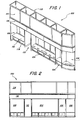
- FIG. 1 illustrates one embodiment of a color pallet display system according to one implementation of the invention.
- the display system 100 includes a plurality of side-by-side display sections 102, 104, 106, and 108.
- the display sections may serve as areas where various paint color samples and/or literature may be displayed.
- the display system 100 also includes an area 110 where a color selection kiosk may be placed.
- the display system may also include an upper structure 112 supported by the side walls of lower display sections 102,104, 106 and 108.
- the upper structure 112 may serve to support display panels 114 for advertising and/or other purposes. Additionally, the upper structure 112 may also include a section 116 where brand headers may be placed.
- the display sections 102,104, 106 and 108 may also include counter surfaces 116 and cabinets 118.
- Figure 2 illustrates a front view of the modular color palette display system 100 illustrated in Figure 1 according to one embodiment of the invention.
- This configuration of the display assembly shows a rounded end-section 108 on the left end of the display assembly 100.
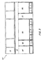
- FIG. 3 illustrates a different embodiment of a color palette modular display system according to one embodiment of the invention.
- the display sections 102,104, 106, 108, and kiosk area 110 have been rearranged so that the rounded end-section 108' is at the right end of the display assembly 100'. It is to be understood that the display sections 102,104, 106, and 108 and the kiosk area 110 may be interchangeable and/or rearranged in different positions without departing from the invention.
- Figure 4 illustrates how the modular display system 100 found in Figure 1 may be constructed according to one embodiment of the invention.
- a plurality of interchangeable side walls 402,404, 406,408, 410 serve to define the various display sections 102, 104, 106,108, and kiosk area 110.
- a plurality of cabinets 412 may be joined together to serve as the base as support for the various side walls 402,404, 406,408, and 410.
- one or more brackets 502 may be fastened to the side walls 402, 404, 406, 408, and 410 and serve to anchor the side walls to the floor or supporting surface according to one embodiment of the invention. Installation of the side walls and cabinet system may involve drilling holes onto the floor or supporting surface so that a fastener may be passed through the bracket and coupled to the floor.
- Figure 6 illustrates how a bracket 602 may be coupled to the back portion of one or more cabinets 412 and to the floor secure the display system 100 according to one embodiment of the invention.
- Figure 7 illustrates how a plurality of back panels 702 may be coupled along the back portion of the modular display system according to one embodiment of the invention.
- a plurality of angle brackets 704 serve to couple the back panels 702 to the side walls 402, 404, 406, 408, 410.
- Flat braces 706 serve to couple the back panels 702 to the back portions of the cabinets 412 and to other back panels.
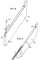
- Figure 8 illustrates an embodiment of a side wall 802 (e.g., 402, 404, 406, 408, 410) with a recessed portion 804 along the lower portion of the front bottom portion of the wall 802 according to one embodiment of the invention.
- This recessed portion 804 serves to receive a mounting bracket 806.
- the bracket may be fastened to the wall 802 with one or more fasteners 808.
- the bracket 806 may be attached to the floor or surface on which the wall is supported with one or more fasteners.
- the wall 802 may also include an opening 810 near the lower back edge of the wall 802 through which electrical cable may be passed.
- the wall 802 may also have a notched region 812 which serves to receive and support an upper display region.
- the notched region may include a protrusion 814 ( Fig. 1 ) which helps to secure the upper display region.
- Figure 9 illustrates how a wood detail edge 902 may be slideably engaged to the front edge of the wall 802 according to one embodiment of the invention.
- the detail edge 902 is slid up, along side grooves 904 on the front edge of the wall 802, until it reaches the top of the front edge and is flush with the bottom of the Rosetta detail 906 as illustrated in Figure 10 .
- FIG 11 illustrates how a curved cabinet 1102 may be constructed according to one embodiment of the invention.
- the curved cabinet 1102 includes a curved enclosure 1104 which is fastened to a base section 1108 and a top surface 1106.
- the top surface 1106 includes an opening 1107 to permit mounting of a holder 1206.
- the back surface 1112 of the curved enclosure 1104 may also include an opening 1110 for passing electrical conduit.
- Figure 12 illustrates a cover assembly 1200 including a cover surface 1202 with an opening 1204 and a holder 1206 on which display information (e.g., brochures, leaflets, booklets, etc.) may be inserted according to one embodiment of the invention.
- the holder 1206 is fastened to the underside of the cover surface 1202 using one or more fasteners 1210.
- This cover assembly 1200 is placed over the top surface 1106 of the curved cabinet 1102 and fastened.
- the top surface 1202 of the cover assembly 1200 may also include an opening 1208 through which electrical conduit may pass.
- Figure 13 illustrates how the end display section 108 may receive the curved cabinet 1102 on which surface 1200 may be placed with fasteners according to one embodiment of the invention.
- the curved cabinet 1102 is placed along the bottom of a side wall 1302 and a back wall or panel 1304 in the display system 100.
- Figures 14 and 15 illustrate an embodiment of an upper structure 112 ( Fig. 1 ) including a plurality of upper frame combinations 1400 and 1500 that may be placed on top of the display sections 102, 104, 106, 108 and 110 according to one embodiment of the invention.
- Figure 14 illustrates an upper frame combination 1400 including three frame modules 1404,1406, 1408 that have been coupled together according to one embodiment of the invention.
- a plurality of light-supporting surfaces 1402 are attached along the lower portion of the frame modules 140 to the frames 1404, 1406, 1408.
- the light-supporting surfaces 1402 may serve to mount lights which help illuminate the display sections 102,104, 106,108 and kiosk area 110, and/or the signs mounted along the front of the upper structure 112.
- Figure 15 similarly illustrates a combination of three frame modules that have been coupled together according to one embodiment of the invention.
- Frame modules 1502 and 1504 may be similar to the frame modules illustrated in Figure 14 .
- Frame module 1506 corresponds to the end section 108. Said end frame module 1506 is used to match the curved cabinet along one end of the display module 100.
- Figure 16 illustrates an example of a single display frame module 1404 which may be composed of metal, wood, plastic and any-other type of material or a plurality of materials or composite materials according to various implementations of the invention.
- the display frame module 1404 may be designed with openings 1602 and 1604 which permit use of a forklift to lift the frame module 1404 or combination of modules 1400 or 1500 during assembly of the display module 100.
- the prongs of a forklift may fit through openings 1602 and 1604 to lift one or more modules.
- the lower frame of the display frame module 1404 may also include one or more openings 1606 through which electrical conduit for lighting and other purposes may be passed.
- Figure 17 illustrates an upper end-module section 1506 as shown in Figure 15 according to one embodiment of the invention.
- the upper end-module section 1506 has a diagonal surface 1702 corresponding to the curved edge of the corresponding lower display section 108.
- the various modules illustrated in Figures 14 through 17 may be arranged in a number of ways depending on the retail location, the length of display area available, and how the display system 100 is to be oriented. While interchangeable modules 1404, 1406, 1408, 1502, and 1504 may be used along the middle portions of the upper structure 112, the slanted or curved end modules (e. g., 1506) may need to be rearranged depending on the orientation or desired configuration of the display system 100.
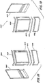
- Figures 18 and 19 illustrate how left side and right side end modules may be constructed using interchangeable parts according to one embodiment of the invention.
- Figure 18 illustrates a left side setup 1800 for an end-section display frame constructed using a back frame 1802, a front upper frame 1804, and a front lower frame 1806. Additionally, retaining channel 1808 and 1810 serve to secure signage or advertising panels to the front of the display frame 1800.
- Figure 19 illustrates a right side frame 1900 similar to frame 1506 ( Fig. 17 ).
- the interchangeability of this end-section display frame is illustrated here.
- the same back frame 1802 may be used as in the left side frame 1800.
- By rotating front frames 1804 and 1806 one hundred eighty degrees, the same frames as those used in the left side frame ( Fig. 18 ) may be used for the right side display frame 1900.
- the only different parts that may be needed to construct the right-handed display frame 1900 are retaining channels 1908 and 1910.
- Figure 20 illustrates how a plurality of upper display frames 2002 may be mounted on a lower display section 2003 according to one embodiment of the invention.
- the side walls 2004, 2006 include rear notches 2008 (e. g., 812, 814 in Fig. 1 ) and front points 2010 on which the upper display frames 2002 may be supported and fastened.
- the upper display frames 2002 may also be fastened to the back panel walls 2012.
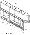
- Figure 21 illustrates how lower display sections 102-108 and kiosk area 110 may be arranged and upper display modules 112 may be mounted on the lower display sections 102-108 and kiosk area 110 according to one embodiment of the invention.
- the upper display frames 1400 ( Fig. 14 ) and 1500 ( Fig. 15 ) have been mounted and secured to the lower display sections 102-108 and kiosk area 110.
- Figure 22 illustrates an upper display frame 2200 with a light-supporting surface 2202 which is attached to the frame by brackets 2204 and a plurality of fasteners 2206 according to one embodiment of the invention.
- the light-supporting fixture 2202 serves to support one or more lights on either the upper surface or lower surface of the fixture 2202.
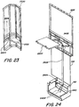
- Figure 23 illustrates an end section 2300 of an upper display frame on which a light support fixture 2302 may be fastened according to one embodiment of the invention.
- support fixture 2302 also serves to support lights on the upper surface and/or lower surface of the fixture 2302.
- a plurality of brackets 2304 and fasteners 2306 may couple the fixture 2302 to the side frame 2300.
- the same support fixture 2302 may be used in both the end section and other upper display frames. Such interchangeability of parts reduces the cost of manufacturing and simplifies installation.
- Figure 24 illustrates how electrical wires 2402 may be routed throughout various portions of the lower and upper display assemblies according to one embodiment of the invention.
- Electrical box 2404 may be housed within the lower cabinet 412.
- Conduit 2406 may carry electrical wires 2402 from the electrical box 2404 to the upper display area.
- the wires 2402 may be coupled to the lights on the upper or lower surfaces of the light-supporting fixture 2202.
- Electrical box 2404 may also include conduit 2410 through the side of box 412 to carry electricity to and/or from adjacent cabinet sections.
- the lower portion of frame 1802 also includes openings 2408 through which a conduit 2406 may be passed.
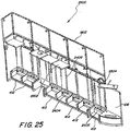
- Figure 25 illustrates how electrical wiring may be ran throughout a complete display module 2500 according to one embodiment of the invention.
- the plurality of lower cabinets 412 may include a plurality of electrical boxes 2404 with electrical conduit 2406 running along the rear portion of the display module 2500 to light-supporting fixtures 2202.
- the electrical boxes 2404 may also include an electrical ballast 2502 to which the electrical wires connect. While this figure illustrates one way of routing electrical wires throughout the display module 2500, other routing schemes are also possible without departing from the invention.
- FIG. 26 illustrates how cabinet section 110 ( Fig. 1 ) may include an electrical outlet plug 2602 which may be connected via wires 2604 to another electrical outlet according to one embodiment of the invention.
- the electrical plug 2602 may provide electrical power to a kiosk, lights, or other devices that may be inserted in section 110.
- Figure 27 illustrates an embodiment of the display system 2700 to which a plurality of countertops, signage, and headers may be mounted according to one embodiment of the invention.
- Some countertops may be flat, such as 2702, while other countertops, such as 2704, may include an opening 2706 to hold a countertop brochure holder 2708.
- Such countertops may be mounted on top of the lower cabinets 412.
- the lower portions of the upper display racks 2710 may serve to hold in-line brand headers 2712 through either clip-on, pressure or other types of fastening means.
- the end display unit 2714 may include a special banner header 2716 that conforms to the shape of the frame 2714.
- the upper portion of the display frames 2710 may hold various display information on panels 2718.
- a plurality of end covers 2720 may be slideably mounted to the lower front edge of the walls 402-410, 802, 1303 to cover-up the lower brackets 806 securing the walls to the floor.
- Figure 28 illustrates how graphic display panels 2718 may be mounted on the upper display frames 2710 according to one embodiment of the invention.
- Graphic display panel holders 1808 and 1810 are mounted along the frame edges to support and secure the display panels 2718 while seam covers 2808 are used to cover the gaps between the display panels 2718.
- Figure 29 illustrates a color display pallet 2902 that may be mounted on top of a counter area 2702 according to one embodiment of the invention.
- the color display pallet 2906 may include a plurality of color sample holders to hold color samples and brochures.
- the color display pallet 2902 may also have an upper display area 2904 on which information may be displayed.
- a plurality of fasteners 2908 may be used to secure the color display pallet 2902 to the counter surface 2702.
- the upper display area 2904 may also be attached to the counter display pallet 2902 by fasteners and/or brackets.
- Figure 30 illustrates a paint selection kiosk 3002 and how it may be inserted into a display region 110 ( Fig. 1 ) between walls 3006 and 3008 according to one embodiment of the invention.
- the upper portion of the display region 110 may also include a panel 3004 to cover up any space between the top of the display kiosk 3002 and the display region 110.
- FIGS 31-33 illustrate the various components that make up the paint selection kiosk according to one embodiment of the invention.
- FIG 31 illustrates a front-side perspective view of the paint selection kiosk cabinet 3100 according to one embodiment of the invention.
- the paint selection and coordination kiosk 3100 includes a cabinet frame 3102, which may be made from a metal, wood, and/or other materials, onto which a front panel 3104, side panels 3106 and 3108, a back panel 3110 and a pop cover 3112 are attached with fasteners 3114.
- slanted portions 3105 may be coupled along the vertical edges of the front panel 3104.
- the front panel 3104 may also include a first opening 3116 to permit viewing of a display screen that may be mounted within the cabinet 3100.
- the front panel 3104 may include a second opening to hold a color-sensing device 3118.
- the front panel 3104 also includes one or more openings 3119 behind which one or more speakers may be mounted.
- the front of the paint selection and coordination kiosk 3100 may also include a horizontal or semi-horizontal surface 3120 with an opening 3122 from which printer paper may be collected.
- a pair of vertically swinging doors 3124 serve to enclose a compartment area. The doors 3124 may be hung from the cabinet frame 3102.
- Figure 32 illustrates a back-side view of the paint selection kiosk cabinet 3100 illustrated in Fig. 31 according to one embodiment of the invention.
- One or more rails 3202-3207 may serve to support one or more horizontal surfaces 3208, 3210, and 3212.
- a first horizontal surface 3208 may be supported by and/or coupled to rails 3202 and 3203.
- a display device (e.g. monitor and/or screen) 3214 may be mounted on the first horizontal surface 3208 such that the display of the device 3214 is visible through opening 3116 in the front panel 3104 of the kiosk 3100.
- a second horizontal supporting surface 3210 may be supported by, or coupled to, horizontal rails 4204 and 3205.
- Horizontal surface 3210 may serve to support one or more devices.
- a power supply 3216, speakers 3218 and a color-sensing device or spectrophotometer 3220 may be mounted to and/or attached to horizontal surface 3210.
- Various different brackets or fasteners may secure the speakers 3218, color-sensing device 3220 and power supply device 3216 to the cabinet according to one embodiment of the invention.
- a third horizontal surface 3212 may be mounted on and/or secured to horizontal rails 3206 and 3207 of the cabinet frame 3102.
- a processing unit e.g., computer
- the processing unit 3230 may be secured to the horizontal surface 3212.
- the kiosk cabinet frame 3102 may also include side panels 3222 fastened to a lower portion of the cabinet frame 3102.
- Supporting members 3224 may be coupled to the lower side panel 3222 by one or more brackets or perpendicularly supporting members 3226.
- the supporting members 3224 may support the cabinet 3100 on a plurality of legs or wheels 3228.
- the supporting legs or wheels 3228 may include.a leveling or height adjusting mechanism such as a nut and thread bolt.
- a keyboard holder and/or mouse holder 3232 may be mounted on the side panel 3222 on the lower portion of the cabinet frame 3102.
- a keyboard or mouse stored in the holder 3232 may be accessed through an opening 3234 in the front of the paint selection kiosk 3100.
- the opening 3234 may be accessed by opening one of the lower doors 3124 of the kiosk 3100.
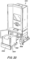
- Figure 33 illustrates a front perspective view of the kiosk 3100 showing how a printer 3302 may be integrated as part of the kiosk 3100 according to one embodiment of the invention.
- the printer 3302 may be mounted on a rolling platform or cart 3304 so that it may be easily moved in and/or out of the kiosk compartment 3300.
- the printer platform 3304 may also include a trim 3306 along the lower front part of the printer platform or dolly 3304 such that it matches the trim 3308 along the lower edge of the kiosk cabinet 3100.
- the printer 3302 may be communicatively coupled to the computer or processing unit 3230 in such a way that permits removal of the printer 3302.
- the printer 3302 may be coupled to the computer by cables long enough to permit removing the printer 3302 and cart 3304 from the compartment 3300 without first unplugging the cables.
- the kiosk illustrated in Figs. 31 - 33 may be configured to aid a person in selecting a starting color (e.g., starting or desired paint color) as well as provide complementary, harmonious, and/or aesthetically pleasing paint colors.
- a starting color e.g., starting or desired paint color
- such kiosk may serve as a paint color selector and coordinator for paint projects such as a painting interiors (e.g., rooms, etc.) or the house exteriors.
Landscapes
- Physics & Mathematics (AREA)
- General Physics & Mathematics (AREA)
- Engineering & Computer Science (AREA)
- Theoretical Computer Science (AREA)
- Devices For Indicating Variable Information By Combining Individual Elements (AREA)
- Display Racks (AREA)
- Illuminated Signs And Luminous Advertising (AREA)
Claims (18)
- Modulpräsentationsbaugruppe, die umfasst:eine Mehrzahl von auswechselbaren vertikal positionierten Seitenwänden (402, 404, 406, 408, 410), wobei jede Seitenwand ein unteres Ende und ein oberes Ende aufweist, wobei jede Seitenwand eine oder mehrere Halterungen (502) zum Befestigen des unteren Endes der Seitenwand beinhaltet, so dass die Seitenwand an einer Bodenbasis verankert wird, wobei die Seitenwand eine gekerbte Region (812) hinten in dem oberen Ende aufweist, wobei die Räume zwischen benachbarten Seitenwänden eine Mehrzahl von Präsentationsteilbereichen (102, 104, 106, 108) definieren;eine Mehrzahl von auswechselbaren Rückplatten (702), die sich über den Seitenwänden erstrecken;eine Mehrzahl von Haltewinkeln (704) zum Befestigen der Rückplatten an der Mehrzahl von auswechselbaren Seitenwänden, um ein Ende des Raums zwischen den Seitenwänden zu umschließen;eine Mehrzahl von auswechselbaren Kästen (412), wobei die Kästen miteinander verbunden sind, um als Träger für die vertikal positionierten Seitenwände zu dienen;eine Mehrzahl von Flachklammern (706), die jeweils einen auswechselbaren Kasten (412) der Mehrzahl von auswechselbaren Kästen mit einer auswechselbaren Rückplatte der Mehrzahl von auswechselbaren Rückplatten zwischen benachbarten Seitenwänden verbinden;eine obere Struktur (112), die von den vertikal positionierten Seitenwänden getragen wird, wobei die obere Struktur so ausgelegt ist, dass sie in den gekerbten Regionen in dem oberen Ende der vertikal positionierten Seitenwände aufgenommen und von diesen getragen wird und dass sie an den vertikal positionierten Seitenwänden befestigt wird; undPräsentationsfelder (114), die auf der oberen Struktur montiert sind.
- Modulpräsentationsbaugruppe nach Anspruch 1, wobei jede vertikal positionierte Seitenwand (402, 404, 406, 408, 410) auch einen Vorsprung (814) innerhalb der gekerbten Region (812) in dem oberen Ende der Seitenwand aufweist, um die obere Struktur zu befestigen.
- Modulpräsentationsbaugruppe nach Anspruch 1, wobei die obere Struktur (112) eine Mehrzahl von auswechselbaren Rahmenmodulen (1404, 1406, 1408) beinhaltet, die miteinander verbunden sind, wobei jedes Rahmenmodul auch an einem Abschnitt einer Rückplatte (702) befestigt ist.
- Modulpräsentationsbaugruppe nach Anspruch 3, wobei die obere Struktur (112) Beleuchtungsträgerflächen (2202) beinhaltet und ferner zumindest einen Beleuchtungskörper beinhaltet, der auf den Beleuchtungsträgerflächen montiert ist, wobei der zumindest eine Beleuchtungskörper so montiert ist, dass zumindest ein Präsentationsteilbereich der Mehrzahl von Präsentationsteilbereichen (102, 104, 106, 108) beleuchtet wird.
- Modulpräsentationsbaugruppe nach Anspruch 3, wobei die obere Struktur (112) ferner ein horizontales Rahmenelement mit einer oder mehreren Öffnungen (1602, 1604) umfasst, die so bemessen sind, dass sie eine Gabelstaplerzinke aufnehmen, um das Heben der oberen Struktur mit einem Gabelstapler zu ermöglichen.
- Modulpräsentationsbaugruppe nach Anspruch 3, die ferner einen Endteilbereichsrahmen (1506) umfasst, der mit einem der auswechselbaren Rahmenmodule verbunden ist, wobei der Endteilbereichsrahmen so strukturiert ist, dass er mit jedem Ende der oberen Struktur (112) verbunden werden kann.
- Modulpräsentationsbaugruppe nach Anspruch 1, die ferner einen Farbauswahlverkaufsstand (3002) umfasst, der in einem Raum zwischen zwei benachbarten Seitenwänden (402, 404, 406, 408, 410) positioniert ist, wobei der Verkaufsstand eine erste Öffnung (3116) für einen Präsentationsbildschirm und eine zweite Öffnung für eine Farberfassungsvorrichtung (3118) aufweist.
- Modulpräsentationsbaugruppe nach Anspruch 1, die ferner eine Farbpräsentationspalette (2902) umfasst, die so ausgelegt ist, dass sie eine Mehrzahl von Farbproben und Farbprobenbroschüren hält.
- Modulpräsentationsbaugruppe nach Anspruch 1, die ferner eine oder mehrere Arbeitsplatten (2702, 2704) umfasst, die auf der Mehrzahl von auswechselbaren Kästen montiert ist.
- Modulpräsentationsbaugruppe nach Anspruch 9, wobei die zumindest eine Arbeitsplatte (2702, 2704) eine Öffnung (2706) und eine Fachliteraturhalterung (2708) beinhaltet, die unterhalb der Öffnung montiert ist, um Fachliteratur durch die Öffnung aufzunehmen und anzuzeigen.
- Modulpräsentationsbaugruppe nach Anspruch 8, wobei die Farbpräsentationspalette (2902) über der Mehrzahl von auswechselbaren Kästen montiert ist.
- Verfahren zum Herstellen einer Modulpräsentationsbaugruppe, das umfasst:Befestigen einer Mehrzahl von auswechselbaren vertikal positionierten Seitenwänden (402, 404, 406, 408, 410) an einer Bodenbasis durch Anbringen einer oder mehrerer Halterungen an der Seitenwand und an der Bodenbasis, so dass die Seitenwand an der Bodenbasis verankert wird, wobei jede Seitenwand ein unteres Ende und ein oberes Ende und eine gekerbte Region (812) in dem oberen Ende aufweist;Befestigen einer Mehrzahl von auswechselbaren Rückplatten (702) an den Seitenwänden unter Verwendung von Haltewinkeln, um ein Ende des Raums zwischen den Seitenwänden zu umschließen;Befestigen einer Mehrzahl von auswechselbaren Kästen (412) an den Rückplatten in einem Raum zwischen den benachbarten Wänden und an der Bodenbasis unter Verwendung einer Mehrzahl von Flachklammern, wobei die Kästen miteinander verbunden sind, um als Träger für die Seitenwände zu dienen; undZusammenbauen einer oberen Struktur (112) durch:Verbinden einer Mehrzahl von auswechselbaren Präsentationsrahmenmodulen (1404, 1406, 1408) miteinander;Verbinden eines Endteilbereichsrahmens (1506) mit den auswechselbaren Präsentationsrahmenmodulen, wobei der Endteilbereichsrahmen und die auswechselbaren Präsentationsrahmenmodule so ausgelegt sind, dass sie auf das obere Ende der Seitenwände und in die gekerbten Regionen in dem oberen Ende der Seitenwände passen; undHeben der oberen Struktur über die Seitenwände, so dass die obere Struktur von den Seitenwänden getragen und in den gekerbten Regionen aufgenommen und von diesen getragen wird.
- Verfahren zum Herstellen einer Modulpräsentationsbaugruppe nach Anspruch 12, die ferner das Zusammenbauen der oberen Struktur (112) durch Montieren einer Beleuchtungsträgerbefestigung (2302) auf den Präsentationsrahmenmodulen der oberen Struktur umfasst.
- Verfahren zum Herstellen einer Modulpräsentationsbaugruppe nach Anspruch 12, die ferner das Montieren eines horizontalen Rahmenelements auf der oberen Struktur (112) umfasst, wobei das horizontale Rahmenelement eine oder mehrere Öffnungen (1602, 1604) aufweist, die so bemessen sind, dass sie eine Gabelstaplerzinke aufnehmen, um ein Heben der oberen Präsentationsrahmenstruktur mit einem Gabelstapler zu ermöglichen.
- Verfahren zum Herstellen einer Modulpräsentationsbaugruppe nach Anspruch 12, das ferner das Positionieren eines Farbauswahlverkaufsstands (3002) zwischen zwei benachbarten Seitenwänden (402, 404, 406, 408, 410) umfasst, wobei der Verkaufsstand eine erste Öffnung (3116) für einen Bildschirm und eine zweite Öffnung für eine Farberfassungsvorrichtung (3118) aufweist.
- Verfahren zum Herstellen einer Modulpräsentationsbaugruppe nach Anspruch 12, die ferner das Montieren einer oder mehrerer Arbeitsplatten (2702, 2704) auf der Mehrzahl von auswechselbaren Kästen umfasst.
- Verfahren zum Herstellen einer Modulpräsentationsbaugruppe nach Anspruch 12, die ferner das Montieren einer Farbpräsentationspalette (2902) über der Mehrzahl von auswechselbaren Kästen umfasst.
- Verfahren zum Herstellen einer Modulpräsentationsbaugruppe nach Anspruch 12, wobei das Verbinden des Endteilbereichsrahmens ferner beinhaltet: Zusammenbauen der auswechselbaren Komponenten auf eine Weise, so dass ein erster Endteilbereich gebildet wird, und Zusammenbauen der auswechselbaren Komponenten auf eine andere Weise, so dass ein zweiter Endteilbereich gebildet wird.
Applications Claiming Priority (2)
| Application Number | Priority Date | Filing Date | Title |
|---|---|---|---|
| US10/702,907 US7789472B2 (en) | 2003-11-05 | 2003-11-05 | Modular color pallet display system |
| PCT/US2004/036802 WO2005046400A1 (en) | 2003-11-05 | 2004-11-04 | Modular color pallet display system |
Publications (2)
| Publication Number | Publication Date |
|---|---|
| EP1681964A1 EP1681964A1 (de) | 2006-07-26 |
| EP1681964B1 true EP1681964B1 (de) | 2020-03-25 |
Family
ID=34573333
Family Applications (1)
| Application Number | Title | Priority Date | Filing Date |
|---|---|---|---|
| EP04818628.2A Expired - Lifetime EP1681964B1 (de) | 2003-11-05 | 2004-11-04 | Modulares farbpalettendarbietungssystem |
Country Status (6)
| Country | Link |
|---|---|
| US (1) | US7789472B2 (de) |
| EP (1) | EP1681964B1 (de) |
| CN (1) | CN100490709C (de) |
| CA (1) | CA2544580C (de) |
| ES (1) | ES2795367T3 (de) |
| WO (1) | WO2005046400A1 (de) |
Families Citing this family (46)
| Publication number | Priority date | Publication date | Assignee | Title |
|---|---|---|---|---|
| HRPK20050879B3 (en) * | 2005-10-05 | 2008-03-31 | Knepr Dag | Multipurpose showcase with movable shelves particularly for marketing the goods pallets |
| JP4647507B2 (ja) * | 2006-01-31 | 2011-03-09 | 本田技研工業株式会社 | リザーブタンク構造 |
| US8678825B2 (en) * | 2008-12-12 | 2014-03-25 | Paul Mutimear | Display device |
| US9563342B2 (en) | 2009-07-22 | 2017-02-07 | Behr Process Corporation | Automated color selection method and apparatus with compact functionality |
| DE102010013768B4 (de) * | 2010-03-31 | 2012-05-31 | Poggenpohl Möbelwerke GmbH | Küchenmodul |
| CN104820516B (zh) | 2010-05-03 | 2018-08-17 | 贝洱工艺公司 | 交互式色彩中心显示设备 |
| CA136217S (en) * | 2010-07-06 | 2011-02-14 | Alexia Holdings Inc | Modular storage unit |
| US8479925B2 (en) * | 2010-07-19 | 2013-07-09 | Newell Window Furnishings, Inc. | Display system |
| USD641991S1 (en) | 2010-08-12 | 2011-07-26 | Behr Process Corporation | Single wall display |
| USD642399S1 (en) | 2010-08-12 | 2011-08-02 | Behr Process Corporation | Wall color center display with modules |
| USD641989S1 (en) | 2010-08-12 | 2011-07-26 | Behr Process Corporation | Single wall core color center display module |
| USD641990S1 (en) | 2010-08-12 | 2011-07-26 | Behr Process Corporation | Single wall display |
| USD641988S1 (en) | 2010-08-12 | 2011-07-26 | Behr Process Corporation | Wall display |
| USD641986S1 (en) | 2010-08-12 | 2011-07-26 | Behr Process Corporation | Wall core color center display module |
| USD641987S1 (en) | 2010-08-12 | 2011-07-26 | Behr Process Cororation | Wall display |
| USD669281S1 (en) | 2010-08-12 | 2012-10-23 | Behr Process Corporation | Kiosk module |
| USD641992S1 (en) | 2010-08-12 | 2011-07-26 | Behr Process Corporation | Single wall core color center display |
| USD631679S1 (en) | 2010-08-12 | 2011-02-01 | Behr Process Corporation | Display module |
| US8689493B2 (en) | 2010-09-01 | 2014-04-08 | Behr Process Corporation | Truss based display system |
| US8931746B2 (en) * | 2011-02-25 | 2015-01-13 | Benchmarc Display Inc. | Apparatus for supporting and displaying paint color cards |
| US8701570B2 (en) | 2011-05-27 | 2014-04-22 | Capstone Innovations, Llc | Expandable modular interlocking pallet system |
| US9532660B2 (en) * | 2011-06-30 | 2017-01-03 | Pepsico, Inc. | Refrigerated merchandise display system |
| EP2550897B1 (de) * | 2011-07-29 | 2013-08-28 | Vieler International GmbH & Co. KG | System zum modularen Aufbau von Theken, insbesondere Verkaufstheken |
| USD685589S1 (en) * | 2011-10-25 | 2013-07-09 | Six Continents Hotels, Inc. | Convertible bar and food station |
| US9237803B2 (en) * | 2011-11-30 | 2016-01-19 | Paragon Furniture LP | Modular shelving systems and methods |
| USD708872S1 (en) * | 2012-10-09 | 2014-07-15 | Behr Process Corporation | Central color center display |
| USD699056S1 (en) * | 2012-10-09 | 2014-02-11 | Behr Process Corporation | Color center display |
| USD698189S1 (en) * | 2012-10-09 | 2014-01-28 | Behr Process Corporation | Central color center display |
| USD704967S1 (en) * | 2013-06-17 | 2014-05-20 | Insurance Lounge Franchise Company, Inc. | Retail display |
| USD776463S1 (en) | 2013-10-17 | 2017-01-17 | Behr Process Corporation | Core color display module |
| USD758105S1 (en) * | 2013-10-25 | 2016-06-07 | Artist Design Studio KFT. | Fixture for presentation of electronic consumer devices |
| USD757465S1 (en) | 2013-12-18 | 2016-05-31 | Behr Process Corporation | Color center display |
| US9483963B2 (en) | 2013-12-18 | 2016-11-01 | Behr Process Corporation | Display assembly and system for paint sample cards |
| USD707991S1 (en) | 2013-12-18 | 2014-07-01 | Behr Process Corporation | Color center display arrays |
| USD715079S1 (en) | 2013-12-18 | 2014-10-14 | Behr Process Corporation | Color center display array |
| CN103927931A (zh) * | 2014-05-14 | 2014-07-16 | 长沙学院 | 一种智能趣味语音型机械通用教学仪 |
| US9468314B2 (en) * | 2014-05-26 | 2016-10-18 | Afi Licensing Llc | Display system for flat article |
| USD781079S1 (en) * | 2015-06-11 | 2017-03-14 | Pepsico, Inc. | Display panel |
| USD793137S1 (en) | 2015-07-21 | 2017-08-01 | Masterchem Industries, Llc | Color center display |
| US9936826B2 (en) * | 2015-08-21 | 2018-04-10 | Apple Inc. | Modular wall system for displaying a product |
| USD821129S1 (en) * | 2015-10-12 | 2018-06-26 | Pepsico, Inc. | Refreshment station |
| US10885575B2 (en) | 2015-12-04 | 2021-01-05 | Behr Process Corporation | Interactive paint product selection and ordering system, apparatus, and non-transitory computer readable medium |
| USD822764S1 (en) | 2016-04-11 | 2018-07-10 | Pepsico, Inc. | Vending machine |
| GB201700060D0 (en) * | 2017-01-03 | 2017-02-15 | Ec Goundworks Ltd | Modular safety station |
| USD858153S1 (en) * | 2017-05-05 | 2019-09-03 | Apple Inc. | Retail display |
| US11000134B2 (en) * | 2018-11-20 | 2021-05-11 | Target Brands, Inc. | Tiered display unit |
Family Cites Families (50)
| Publication number | Priority date | Publication date | Assignee | Title |
|---|---|---|---|---|
| US3125385A (en) | 1964-03-17 | friedman | ||
| US1678522A (en) | 1928-07-24 | Stoke shelving front unit | ||
| US1381501A (en) | 1920-09-17 | 1921-06-14 | Grand Rapids Show Case Co | Shelving construction |
| US2206353A (en) | 1937-06-02 | 1940-07-02 | Jesse J Hill | Preformed knock-down display article |
| US2328130A (en) * | 1940-02-10 | 1943-08-31 | Genevieve M Earle | Method of assembling mechanical refrigerators |
| US2999599A (en) | 1958-09-02 | 1961-09-12 | Jentzen Miller Company | Display shelving |
| US3316041A (en) | 1964-04-15 | 1967-04-25 | Kewaunee Technical Furniture C | Modular display case |
| US3675955A (en) * | 1970-03-23 | 1972-07-11 | Regis Mfg Co | Cabinet bracket |
| US3749465A (en) * | 1971-03-22 | 1973-07-31 | Amerock Corp | Knock down cabinet and hardware for assembling the same |
| US3971605A (en) * | 1972-01-27 | 1976-07-27 | Russel M. Sasnett | Modular furnishings |
| CH560029A5 (en) | 1973-06-07 | 1975-03-27 | Kreft Wilhelm | Book or record display shelf - made in sections partially inclined towards the vertical and fitted with light source |
| US3980361A (en) | 1975-03-28 | 1976-09-14 | Jerry Shaw | Expandable display system |
| US4008931A (en) * | 1975-09-17 | 1977-02-22 | Lincoln Manufacturing Company, Inc. | End panel construction for modular units and modular unit embodying the end panel construction |
| DE2546796A1 (de) | 1975-10-18 | 1977-04-21 | Vogt Bueromoebel | Bueromoebel |
| US4116509A (en) | 1976-07-02 | 1978-09-26 | R. C. Smith Company | Modular furniture unit for hospital pharmacies or the like |
| US4148535A (en) | 1977-03-07 | 1979-04-10 | Litton Business Systems, Inc. | Modular display cases |
| IT7723337A1 (it) | 1977-05-09 | 1978-11-09 | Pallavicini Piero | Mobile componibile per la formazione di pareti divisorie attrezzate comprendenti scaffalature, armadi e simili |
| IT7920680U1 (it) * | 1979-02-02 | 1980-08-02 | Citterio Camillo | Struttura di elementi modulari componibili per arredamento. |
| DE2945644C2 (de) * | 1979-11-12 | 1983-06-30 | Rosenthal Ag, 8672 Selb | Variable Ausstellungs- und Ladenregaleinheit |
| DE3046139C2 (de) * | 1980-12-06 | 1984-04-05 | Albin Kaut Display & Design, 7141 Steinheim | Steckregal für Dekorationszwecke |
| US4567698A (en) * | 1983-12-13 | 1986-02-04 | Knoll International, Inc. | Space divider system |
| US4586759A (en) * | 1984-06-18 | 1986-05-06 | Lsi Corporation Of America, Inc. | Modular framing and support system for laboratory furniture |
| SE458129B (sv) * | 1985-01-22 | 1989-02-27 | Sune Sigfrid Lennart Rydqvist | Skaermvaeggsystem |
| US4699270A (en) * | 1985-09-09 | 1987-10-13 | The Union Corporation | Modular packaging system |
| US4938548A (en) * | 1986-04-30 | 1990-07-03 | Shure Manufacturing Corporation | Modular mechanic's workstation |
| US4948203A (en) * | 1988-02-29 | 1990-08-14 | Amstore Corporation | Lighted display case |
| US5199775A (en) * | 1990-11-23 | 1993-04-06 | The Corporate Communications Group, Inc. | Modular exhibitry unit |
| US5439123A (en) * | 1993-08-03 | 1995-08-08 | Harbor Industries, Inc. | Display system |
| US5405192A (en) | 1993-12-07 | 1995-04-11 | Mcgrath; Stephen E. | Modular booth display assembly |
| US6196648B1 (en) * | 1995-02-16 | 2001-03-06 | Kimball International, Inc. | Desk system having stanchion supported overhead storage cabinet |
| US5628415A (en) * | 1995-06-07 | 1997-05-13 | Econo-Rack Storage Equipment Limited | Storage rack and safety bars for use therein |
| US5647648A (en) * | 1995-10-13 | 1997-07-15 | Food Concepts, Inc. | Support structure and assembly method for food court systems |
| JPH09121965A (ja) * | 1995-10-31 | 1997-05-13 | Matsushita Electric Works Ltd | キャビネットの固定構造 |
| CN2262390Y (zh) * | 1996-07-24 | 1997-09-17 | 顾贵强 | 宗教性墙架柜面框结构改进 |
| US5961192A (en) * | 1998-02-06 | 1999-10-05 | The Little Tikes Company | Mobile computer work station |
| DE29803156U1 (de) | 1998-02-23 | 1998-08-06 | Kiehne, Andreas, 37603 Holzminden | Variables Möbelanbausystem |
| DE29805662U1 (de) | 1998-03-20 | 1998-07-16 | Krause, Helge, 15752 Prieros | Schranksystem |
| US6095482A (en) * | 1998-09-14 | 2000-08-01 | Lucent Technologies, Inc. | Universal equipment mounting structure and method of using |
| US6659295B1 (en) | 1999-03-26 | 2003-12-09 | L&P Property Management Company | Adjustable shelving/display system |
| US6533372B1 (en) * | 1999-07-16 | 2003-03-18 | Nolu Plastics, Inc. | Beverage cart |
| US6273531B1 (en) * | 1999-12-15 | 2001-08-14 | Thomasville Furniture Industries, Inc. | Revolving storage hutch |
| USD449077S1 (en) * | 2000-11-29 | 2001-10-09 | Charles Edward Bain | Interactive kiosk |
| DE20100825U1 (de) | 2001-01-17 | 2001-05-31 | Gustav Wellmann GmbH & Co. KG, 32130 Enger | Schrankelement, insbesondere für freistehende, allseitig zugängliche modulare Schrankzeilen |
| US6920727B2 (en) * | 2001-02-14 | 2005-07-26 | Haworth, Inc. | Wall panel arrangement with accessory-supporting top cap |
| US6467856B1 (en) | 2001-03-09 | 2002-10-22 | Oneida, Ltd. | Modular display case |
| US6786017B2 (en) * | 2001-05-07 | 2004-09-07 | L&P Property Management Company | Modular room system and method |
| US6560093B1 (en) * | 2001-06-29 | 2003-05-06 | Ncr Corporation | Carrel computer terminal |
| US7174310B2 (en) * | 2001-10-22 | 2007-02-06 | Bartholomew Julie R | Point of sale cosmetic station |
| DE20203068U1 (de) | 2002-02-27 | 2002-06-27 | Herbstritt, Michael, Dipl.-Ing. (FH), 79336 Herbolzheim | Modular erweiterbares Möbel, insbesondere Bad- oder Duschaccessoire |
| US7175034B2 (en) * | 2002-06-14 | 2007-02-13 | Harbor Industries, Inc. | Modular, adjustable display rack |
-
2003
- 2003-11-05 US US10/702,907 patent/US7789472B2/en not_active Expired - Lifetime
-
2004
- 2004-11-04 CN CNB200480036692XA patent/CN100490709C/zh not_active Expired - Fee Related
- 2004-11-04 WO PCT/US2004/036802 patent/WO2005046400A1/en not_active Ceased
- 2004-11-04 ES ES04818628T patent/ES2795367T3/es not_active Expired - Lifetime
- 2004-11-04 CA CA2544580A patent/CA2544580C/en not_active Expired - Fee Related
- 2004-11-04 EP EP04818628.2A patent/EP1681964B1/de not_active Expired - Lifetime
Non-Patent Citations (1)
| Title |
|---|
| None * |
Also Published As
| Publication number | Publication date |
|---|---|
| WO2005046400A1 (en) | 2005-05-26 |
| CA2544580A1 (en) | 2005-05-26 |
| CN1889868A (zh) | 2007-01-03 |
| CN100490709C (zh) | 2009-05-27 |
| CA2544580C (en) | 2013-12-24 |
| US20050102918A1 (en) | 2005-05-19 |
| ES2795367T3 (es) | 2020-11-23 |
| US7789472B2 (en) | 2010-09-07 |
| EP1681964A1 (de) | 2006-07-26 |
Similar Documents
| Publication | Publication Date | Title |
|---|---|---|
| CA2544580C (en) | Modular color pallet display system | |
| EP0479330B1 (de) | Arbeitsraumeinteilungssystem | |
| US8474193B2 (en) | Wall-mounted modular accessory system | |
| US6490829B1 (en) | Free standing modular architectural beam system | |
| US5974742A (en) | Free standing modular furniture and wall system | |
| CA2634095C (en) | Modular display apparatus | |
| US8327589B2 (en) | Wall-mounted modular accessory system | |
| US8898942B2 (en) | Configurable large-depth panel display | |
| US7654399B2 (en) | Configurable display system and modular display arrangement for consumer electronic devices | |
| US20140268691A1 (en) | Illuminated shelving system | |
| US6796622B2 (en) | Furniture system supporting entertainment electronics in range of widths | |
| US5695261A (en) | Integrally powered modular furniture | |
| US6226931B1 (en) | Modular display system | |
| US6010017A (en) | Modular dispenser and display system | |
| US12336646B2 (en) | Modular wall panel system | |
| US20110163050A1 (en) | Floor and wall-mounted stands with backlighting | |
| HK1252548A1 (zh) | 用於展示产品的模块化墙壁系统 | |
| US6530490B1 (en) | Reconfigurable retail merchandising system | |
| MXPA06004993A (en) | Modular color pallet display system | |
| US20040222720A1 (en) | Display apparatus and method | |
| JP3522496B2 (ja) | 自動販売機のディスプレイ装置 |
Legal Events
| Date | Code | Title | Description |
|---|---|---|---|
| PUAI | Public reference made under article 153(3) epc to a published international application that has entered the european phase |
Free format text: ORIGINAL CODE: 0009012 |
|
| 17P | Request for examination filed |
Effective date: 20060526 |
|
| AK | Designated contracting states |
Kind code of ref document: A1 Designated state(s): DE ES FR GB IE IT |
|
| DAX | Request for extension of the european patent (deleted) | ||
| RBV | Designated contracting states (corrected) |
Designated state(s): DE ES FR GB IE IT |
|
| 17Q | First examination report despatched |
Effective date: 20071024 |
|
| STAA | Information on the status of an ep patent application or granted ep patent |
Free format text: STATUS: EXAMINATION IS IN PROGRESS |
|
| GRAP | Despatch of communication of intention to grant a patent |
Free format text: ORIGINAL CODE: EPIDOSNIGR1 |
|
| STAA | Information on the status of an ep patent application or granted ep patent |
Free format text: STATUS: GRANT OF PATENT IS INTENDED |
|
| RIC1 | Information provided on ipc code assigned before grant |
Ipc: G09F 15/00 20060101ALI20191030BHEP Ipc: A47F 7/00 20060101ALI20191030BHEP Ipc: A47F 3/00 20060101AFI20191030BHEP |
|
| INTG | Intention to grant announced |
Effective date: 20191120 |
|
| GRAS | Grant fee paid |
Free format text: ORIGINAL CODE: EPIDOSNIGR3 |
|
| GRAA | (expected) grant |
Free format text: ORIGINAL CODE: 0009210 |
|
| STAA | Information on the status of an ep patent application or granted ep patent |
Free format text: STATUS: THE PATENT HAS BEEN GRANTED |
|
| AK | Designated contracting states |
Kind code of ref document: B1 Designated state(s): DE ES FR GB IE IT |
|
| REG | Reference to a national code |
Ref country code: GB Ref legal event code: FG4D |
|
| REG | Reference to a national code |
Ref country code: DE Ref legal event code: R096 Ref document number: 602004054577 Country of ref document: DE |
|
| REG | Reference to a national code |
Ref country code: IE Ref legal event code: FG4D |
|
| REG | Reference to a national code |
Ref country code: ES Ref legal event code: FG2A Ref document number: 2795367 Country of ref document: ES Kind code of ref document: T3 Effective date: 20201123 |
|
| REG | Reference to a national code |
Ref country code: DE Ref legal event code: R097 Ref document number: 602004054577 Country of ref document: DE |
|
| PLBE | No opposition filed within time limit |
Free format text: ORIGINAL CODE: 0009261 |
|
| STAA | Information on the status of an ep patent application or granted ep patent |
Free format text: STATUS: NO OPPOSITION FILED WITHIN TIME LIMIT |
|
| 26N | No opposition filed |
Effective date: 20210112 |
|
| REG | Reference to a national code |
Ref country code: DE Ref legal event code: R119 Ref document number: 602004054577 Country of ref document: DE |
|
| GBPC | Gb: european patent ceased through non-payment of renewal fee |
Effective date: 20201104 |
|
| PG25 | Lapsed in a contracting state [announced via postgrant information from national office to epo] |
Ref country code: FR Free format text: LAPSE BECAUSE OF NON-PAYMENT OF DUE FEES Effective date: 20201130 Ref country code: IE Free format text: LAPSE BECAUSE OF NON-PAYMENT OF DUE FEES Effective date: 20201104 |
|
| PG25 | Lapsed in a contracting state [announced via postgrant information from national office to epo] |
Ref country code: GB Free format text: LAPSE BECAUSE OF NON-PAYMENT OF DUE FEES Effective date: 20201104 Ref country code: DE Free format text: LAPSE BECAUSE OF NON-PAYMENT OF DUE FEES Effective date: 20210601 |
|
| REG | Reference to a national code |
Ref country code: ES Ref legal event code: FD2A Effective date: 20220202 |
|
| PG25 | Lapsed in a contracting state [announced via postgrant information from national office to epo] |
Ref country code: IT Free format text: LAPSE BECAUSE OF NON-PAYMENT OF DUE FEES Effective date: 20201104 |
|
| PG25 | Lapsed in a contracting state [announced via postgrant information from national office to epo] |
Ref country code: ES Free format text: LAPSE BECAUSE OF NON-PAYMENT OF DUE FEES Effective date: 20201105 |