EP1681902A1 - Vibrationslautsprecher sowie eine solche Lautsprecher enthaltende Klingelanläute- und Vibrationsvorrichtung - Google Patents
Vibrationslautsprecher sowie eine solche Lautsprecher enthaltende Klingelanläute- und Vibrationsvorrichtung Download PDFInfo
- Publication number
- EP1681902A1 EP1681902A1 EP06290088A EP06290088A EP1681902A1 EP 1681902 A1 EP1681902 A1 EP 1681902A1 EP 06290088 A EP06290088 A EP 06290088A EP 06290088 A EP06290088 A EP 06290088A EP 1681902 A1 EP1681902 A1 EP 1681902A1
- Authority
- EP
- European Patent Office
- Prior art keywords
- inductor
- membrane
- current
- windings
- source
- Prior art date
- Legal status (The legal status is an assumption and is not a legal conclusion. Google has not performed a legal analysis and makes no representation as to the accuracy of the status listed.)
- Withdrawn
Links
Images
Classifications
-
- H—ELECTRICITY
- H04—ELECTRIC COMMUNICATION TECHNIQUE
- H04R—LOUDSPEAKERS, MICROPHONES, GRAMOPHONE PICK-UPS OR LIKE ACOUSTIC ELECTROMECHANICAL TRANSDUCERS; ELECTRIC HEARING AIDS; PUBLIC ADDRESS SYSTEMS
- H04R9/00—Transducers of moving-coil, moving-strip, or moving-wire type
- H04R9/10—Telephone receivers
-
- H—ELECTRICITY
- H04—ELECTRIC COMMUNICATION TECHNIQUE
- H04R—LOUDSPEAKERS, MICROPHONES, GRAMOPHONE PICK-UPS OR LIKE ACOUSTIC ELECTROMECHANICAL TRANSDUCERS; ELECTRIC HEARING AIDS; PUBLIC ADDRESS SYSTEMS
- H04R2400/00—Loudspeakers
- H04R2400/03—Transducers capable of generating both sound as well as tactile vibration, e.g. as used in cellular phones
-
- H—ELECTRICITY
- H04—ELECTRIC COMMUNICATION TECHNIQUE
- H04R—LOUDSPEAKERS, MICROPHONES, GRAMOPHONE PICK-UPS OR LIKE ACOUSTIC ELECTROMECHANICAL TRANSDUCERS; ELECTRIC HEARING AIDS; PUBLIC ADDRESS SYSTEMS
- H04R7/00—Diaphragms for electromechanical transducers; Cones
- H04R7/16—Mounting or tensioning of diaphragms or cones
- H04R7/18—Mounting or tensioning of diaphragms or cones at the periphery
-
- H—ELECTRICITY
- H04—ELECTRIC COMMUNICATION TECHNIQUE
- H04R—LOUDSPEAKERS, MICROPHONES, GRAMOPHONE PICK-UPS OR LIKE ACOUSTIC ELECTROMECHANICAL TRANSDUCERS; ELECTRIC HEARING AIDS; PUBLIC ADDRESS SYSTEMS
- H04R9/00—Transducers of moving-coil, moving-strip, or moving-wire type
- H04R9/02—Details
- H04R9/025—Magnetic circuit
Definitions
- the present invention relates to vibrating speakers of the kind used in portable devices such as mobile phones.
- a ringing function with a vibrate function to signal incoming calls or other events.
- the buzzer and buzzer can also be used for games that the unit can play.
- the ringer speaker can also be used in powered listening mode or in listen and listen mode.
- This transducer is a vibrating loudspeaker comprising a support, an elastic membrane having its periphery fixed to the support, a coil fixed to the membrane, a suspended mass including one or more permanent magnets and a yoke, and springs placed between the support and the suspended mass.
- the mechanical system comprising the membrane and the coil has a natural frequency f 1 f 2 greater than that of another mechanical system comprising the suspended mass and springs.
- Excitation of the coil in a sound frequency range greater than f 1 or including f 1 generates an electromagnetic force that actuates the membrane to produce the buzzer.
- the coil is excited at a frequency of the order of f 2 , which resonates the suspended mass comprising the yoke and the permanent magnet.
- US2002 / 0131612 also describes the realization of the vibrator function by means of a secondary coil fixed to the support. This improves the situation for simultaneous use of the buzzer and buzzer, but at the expense of poorer performance when the buzzer or buzzer is used alone.
- the magnetic circuit comprising the permanent magnet (s) and the cylinder head must be designed so that the magnetic flux is distributed both to the main coil fixed to the membrane and to the secondary coil. This design of the magnetic circuit is not optimal for the excitation of only one of the two coils.
- the secondary coil requires space between the support and the suspended mass, which increases the size of the transducer.
- An object of the present invention is to propose an alternative solution to the problem of the simultaneous use of the ring and the vibrator.
- the invention thus proposes an electromechanical transducer, comprising a support, a membrane having its periphery fixed to the support, inductor windings fixed to the membrane, a suspended mass including at least one permanent magnet and a cylinder head, and return means placed between the support and the suspended mass, wherein a system comprising the diaphragm and the inductor windings has a higher natural frequency than another system comprising the suspended mass and the return means.
- the inductor windings fixed to the membrane comprise two inductor circuits integral with each other and supplied with current in a distinct manner.
- one of the inductive circuits can be supplied in a range of sound frequencies to excite the membrane system - inductor windings and produce a ringing signal, while the other inductor circuit can be powered at a lower frequency to excite the system suspended mass - springs and simultaneously produce a vibrating signal.
- the power of the two circuits being distinct, it is not necessary to accumulate the two excitation currents in the same coil, which requires an amplifier of great dynamics, expensive.
- the magnetic circuit comprising the permanent magnet (s) and the The cylinder head can be optimized to concentrate the magnetic flux in the region where the windings are located, thus providing optimal operation not only when the buzzer and buzzer are activated simultaneously, but also when they are separately.
- the transducer has the further advantage of a relative compactness, which is very significant in portable devices for which miniaturization is an important factor.
- This device comprises a support, a membrane having its periphery fixed to the support, inductor windings fixed to the membrane, a suspended mass including at least one permanent magnet and a yoke, return means placed between the support and the suspended mass, and means for supplying current to the inductor windings.
- a first system comprising the membrane and the inductor windings has a higher natural frequency than a second system comprising the suspended mass and the return means.
- the supply means comprise a first current source capable of producing a variable current in a sound frequency range including or greater than the natural frequency of the first system, and a second current source capable of producing a variable current in a range of vibratory frequencies lower than said sound frequency range and including the natural frequency of the second system.
- the inductor windings fixed to the membrane comprise first and second inductor circuits integral with each other, the first inductor circuit being connected to receive the current from the first source and the second inductor circuit being connected to receive the current from the the second source.
- Yet another aspect of the invention relates to a mobile telephone incorporating such a ringing and vibrating device.
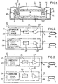
- an electromechanical transducer comprises a support frame 1 which, in the particular schematic example, is in the form of a cylindrical housing whose front face is closed by the membrane 2 of the loudspeaker.
- the housing can also be of another shape, for example oval or oblong.
- This membrane is fixed to the support 1, and its rear face is bonded to a cylindrical element 3 which carries adjoining windings 4, 5 contiguous and concentric.
- the element 3 is floating in an annular gap 6 formed between a central permanent magnet 7 and the cylindrical portion 8 of a cylinder head 9.
- the shape of the annular gap 6 is adapted to that (cylindrical, oval, oblong ... ) of the housing.
- the yoke 9 is closed by a transverse portion 10 parallel to the bottom of the housing 1.
- the magnetic circuit is completed by a pole piece 11 fixed to the magnet 7 in the direction of the membrane, so the magnetic flux is concentrated in the gap 6 receiving the inductor windings.
- Springs 12 for example in the form of elastic blades, are fixed on the one hand to the support 1 and on the other hand to the yoke 9 to suspend the moving mass breech 9 - magnet 7 - pole piece 11 relative to the support 1.
- the mechanical system constituted by this mobile mass 7, 9, 11 suspended by the springs 12 relative to the support 1 has a natural frequency f 2 chosen to be about 150 Hz for example.
- the mechanical system consisting of the membrane 2 and the inductor windings carried by the element 3, which can also oscillate relative to the support 1, has its own frequency f 1 taken much greater than f 2 , for example from 500 to 1000 Hz.
- the inductor windings carried by the element 3 are divided into two circuits 4, 5 of the solenoid type or coils. These two circuits 4, 5 are integral with each other, but supplied separately from respective terminals 14, 15.
- the two circuits 4, 5 can be juxtaposed radially as in the example shown in Figure 1. They can also be juxtaposed axially. In another embodiment, their turns alternate in the axial direction.
- FIG. 2 shows the power supply means 20 for these two coils.
- These means 20 comprise two distinct current sources 21, 22.
- the current source 21 which comprises the sound signal generator 23 delivers on the terminal 14 a high frequency variable current, able to excite the membrane system 2 - element 3.
- the sound frequency range of this current is typically 500 Hz to 10 kHz.
- This source 21 further comprises a digital-to-analog converter (DAC) 25 receiving the digital sound signal and an amplifier 27 whose input is connected to the output of the DAC 25 and the output is connected to the terminal 14.
- DAC digital-to-analog converter
- the current source 22 which comprises the buzzer signal generator 24 delivers on the terminal 15 a variable low frequency current, adapted to excite the resonance mass system 7, 9, 11 - springs 12. This current is typically produced in a narrow band around the resonance frequency of the system (about 150 Hz).
- This source 22 also comprises a DAC 26 receiving the digital vibrator signal and an amplifier 28 whose input is connected to the output of the DAC 26 and the output is connected to the terminal 15.
- the current supply means 20 comprise, in addition to the current sources 21, 22, a switch 30 which makes it possible to increase the power of the sound signal when the vibrator operation is not in use. activated.
- the switch 30 has a position V in which it connects the input of the amplifier 28 of the source 22, which produces the vibrator signal, to the output of the DAC 26 of the same source 22. In this position V, the operation of the device is the same as that described with reference to FIG.
- the switch 30 also has an NV position in which it connects the input of the amplifier 28 of the source 22 to the output of the DAC 25 of the other source 21, which produces the sound signal. In the NV position, the sound signal can thus be emitted at increased power.
- the switch 30 may also be a digital switch.
- one of the two coils may be used for the ear-connected earphone function with a telephone frequency range of 300 Hz to 3400 Hz.
- Many audio channel variants may be derived from this configuration of the two coils. It is possible to provide several amplifiers selected according to the use of the loudspeaker, for example by adding to the previously described amplifiers an analog amplifier for the earphone mode.
Landscapes
- Physics & Mathematics (AREA)
- Engineering & Computer Science (AREA)
- Acoustics & Sound (AREA)
- Signal Processing (AREA)
- Details Of Audible-Bandwidth Transducers (AREA)
- Apparatuses For Generation Of Mechanical Vibrations (AREA)
Applications Claiming Priority (1)
| Application Number | Priority Date | Filing Date | Title |
|---|---|---|---|
| FR0500373A FR2880767B1 (fr) | 2005-01-13 | 2005-01-13 | Haut-parleur vibrant et dispositif de sonnerie et de vibration incorporant un tel haut-parleur |
Publications (1)
| Publication Number | Publication Date |
|---|---|
| EP1681902A1 true EP1681902A1 (de) | 2006-07-19 |
Family
ID=34955150
Family Applications (1)
| Application Number | Title | Priority Date | Filing Date |
|---|---|---|---|
| EP06290088A Withdrawn EP1681902A1 (de) | 2005-01-13 | 2006-01-13 | Vibrationslautsprecher sowie eine solche Lautsprecher enthaltende Klingelanläute- und Vibrationsvorrichtung |
Country Status (2)
| Country | Link |
|---|---|
| EP (1) | EP1681902A1 (de) |
| FR (1) | FR2880767B1 (de) |
Citations (6)
| Publication number | Priority date | Publication date | Assignee | Title |
|---|---|---|---|---|
| US5764751A (en) * | 1995-06-01 | 1998-06-09 | Nec Corporation | Portable telephone set with a vibrator having an automatic switching function |
| US6211775B1 (en) * | 1998-06-15 | 2001-04-03 | Samsung Electro-Mechanics Co., Ltd. | Vibration apparatus capable of generating and externally transmitting a sound wave of audible frequency and transmitting a vibration for notification |
| WO2001041322A1 (en) * | 1999-12-01 | 2001-06-07 | Jae Sung Lee | Integrated vibration and sound generating apparatus |
| EP1149636A1 (de) * | 2000-04-25 | 2001-10-31 | Tokin Corporation | Schwingungserreger mit mehreren Funktionen |
| US20020131612A1 (en) | 2001-03-16 | 2002-09-19 | Samsung Electro-Mechanics Co., Ltd. | Dual magnetic structure of vibration speaker |
| US6487300B1 (en) * | 1999-12-17 | 2002-11-26 | Samsung Electro-Mechanics Co., Ltd. | Vibration speaker |
-
2005
- 2005-01-13 FR FR0500373A patent/FR2880767B1/fr not_active Expired - Fee Related
-
2006
- 2006-01-13 EP EP06290088A patent/EP1681902A1/de not_active Withdrawn
Patent Citations (6)
| Publication number | Priority date | Publication date | Assignee | Title |
|---|---|---|---|---|
| US5764751A (en) * | 1995-06-01 | 1998-06-09 | Nec Corporation | Portable telephone set with a vibrator having an automatic switching function |
| US6211775B1 (en) * | 1998-06-15 | 2001-04-03 | Samsung Electro-Mechanics Co., Ltd. | Vibration apparatus capable of generating and externally transmitting a sound wave of audible frequency and transmitting a vibration for notification |
| WO2001041322A1 (en) * | 1999-12-01 | 2001-06-07 | Jae Sung Lee | Integrated vibration and sound generating apparatus |
| US6487300B1 (en) * | 1999-12-17 | 2002-11-26 | Samsung Electro-Mechanics Co., Ltd. | Vibration speaker |
| EP1149636A1 (de) * | 2000-04-25 | 2001-10-31 | Tokin Corporation | Schwingungserreger mit mehreren Funktionen |
| US20020131612A1 (en) | 2001-03-16 | 2002-09-19 | Samsung Electro-Mechanics Co., Ltd. | Dual magnetic structure of vibration speaker |
Also Published As
| Publication number | Publication date |
|---|---|
| FR2880767B1 (fr) | 2007-04-20 |
| FR2880767A1 (fr) | 2006-07-14 |
Similar Documents
| Publication | Publication Date | Title |
|---|---|---|
| JP3195965U (ja) | デュアル周波数イヤホン構造 | |
| CN102333270B (zh) | 发声器 | |
| EP1257148A2 (de) | Lautsprecher für ein tragbares Kommunikationsgerät | |
| US20120177246A1 (en) | Multi-magnet system and speaker using same | |
| US8571252B2 (en) | Driver assembly for loudspeakers | |
| FR2802760A1 (fr) | Haut-parleur generateur de vibrations | |
| FR2872671A1 (fr) | Actionneur multifonction capable d'empecher la vibration | |
| US8611583B2 (en) | Compact coaxial crossover-free loudspeaker | |
| CN110178383A (zh) | 桥型边缘方式的高分辨率电磁扬声器 | |
| US20070041606A1 (en) | Apparatus and method for noise cancellation in communication headset using dual-coil speaker | |
| KR20030039926A (ko) | 스피커 일체형 리시버 | |
| FR2570238A1 (fr) | Vibrateur electromecanique audio-frequence, destine a la reproduction de vibrations ressenties par le corps humain | |
| JP2003152606A (ja) | 磁気通信装置 | |
| KR20020003169A (ko) | 휴대용 통신 단말기의 수신 유니트 | |
| EP1681902A1 (de) | Vibrationslautsprecher sowie eine solche Lautsprecher enthaltende Klingelanläute- und Vibrationsvorrichtung | |
| JP2012119845A (ja) | 電磁型電気音響変換器 | |
| KR20030059604A (ko) | 스피커 일체형 리시버 | |
| KR100503006B1 (ko) | 소형 스피커 및 그 제조방법 | |
| JP6439894B1 (ja) | スピーカ湾曲振動板 | |
| US5942734A (en) | Noise-attenuating shielding unit and method for loudspeakers | |
| KR100685451B1 (ko) | 휴대용 이동통신 단말기의 리시버 유니트 | |
| KR100957540B1 (ko) | 스피커 | |
| KR20030014819A (ko) | 진동모터 일체형 스피커 | |
| JP5263543B2 (ja) | ダイナミックスピーカーの歪低減方式 | |
| JP2006217518A (ja) | 電気音響変換装置 |
Legal Events
| Date | Code | Title | Description |
|---|---|---|---|
| PUAI | Public reference made under article 153(3) epc to a published international application that has entered the european phase |
Free format text: ORIGINAL CODE: 0009012 |
|
| AK | Designated contracting states |
Kind code of ref document: A1 Designated state(s): AT BE BG CH CY CZ DE DK EE ES FI FR GB GR HU IE IS IT LI LT LU LV MC NL PL PT RO SE SI SK TR |
|
| AX | Request for extension of the european patent |
Extension state: AL BA HR MK YU |
|
| 17P | Request for examination filed |
Effective date: 20061023 |
|
| AKX | Designation fees paid |
Designated state(s): DE ES GB IT |
|
| 17Q | First examination report despatched |
Effective date: 20070830 |
|
| STAA | Information on the status of an ep patent application or granted ep patent |
Free format text: STATUS: THE APPLICATION IS DEEMED TO BE WITHDRAWN |
|
| 18D | Application deemed to be withdrawn |
Effective date: 20080111 |