EP1680997A2 - Cooking apparatus - Google Patents
Cooking apparatus Download PDFInfo
- Publication number
- EP1680997A2 EP1680997A2 EP05107758A EP05107758A EP1680997A2 EP 1680997 A2 EP1680997 A2 EP 1680997A2 EP 05107758 A EP05107758 A EP 05107758A EP 05107758 A EP05107758 A EP 05107758A EP 1680997 A2 EP1680997 A2 EP 1680997A2
- Authority
- EP
- European Patent Office
- Prior art keywords
- heat
- heat reflecting
- reflecting
- unit
- reflecting unit
- Prior art date
- Legal status (The legal status is an assumption and is not a legal conclusion. Google has not performed a legal analysis and makes no representation as to the accuracy of the status listed.)
- Withdrawn
Links
Images


Classifications
-
- H—ELECTRICITY
- H02—GENERATION; CONVERSION OR DISTRIBUTION OF ELECTRIC POWER
- H02G—INSTALLATION OF ELECTRIC CABLES OR LINES, OR OF COMBINED OPTICAL AND ELECTRIC CABLES OR LINES
- H02G11/00—Arrangements of electric cables or lines between relatively-movable parts
- H02G11/02—Arrangements of electric cables or lines between relatively-movable parts using take-up reel or drum
-
- F—MECHANICAL ENGINEERING; LIGHTING; HEATING; WEAPONS; BLASTING
- F24—HEATING; RANGES; VENTILATING
- F24C—DOMESTIC STOVES OR RANGES ; DETAILS OF DOMESTIC STOVES OR RANGES, OF GENERAL APPLICATION
- F24C15/00—Details
- F24C15/10—Tops, e.g. hot plates; Rings
- F24C15/101—Tops, e.g. hot plates; Rings provisions for circulation of air
-
- A—HUMAN NECESSITIES
- A47—FURNITURE; DOMESTIC ARTICLES OR APPLIANCES; COFFEE MILLS; SPICE MILLS; SUCTION CLEANERS IN GENERAL
- A47J—KITCHEN EQUIPMENT; COFFEE MILLS; SPICE MILLS; APPARATUS FOR MAKING BEVERAGES
- A47J37/00—Baking; Roasting; Grilling; Frying
- A47J37/06—Roasters; Grills; Sandwich grills
- A47J37/07—Roasting devices for outdoor use; Barbecues
- A47J37/0704—Roasting devices for outdoor use; Barbecues with horizontal fire box
- A47J37/0709—Roasting devices for outdoor use; Barbecues with horizontal fire box with electric heating elements
-
- A—HUMAN NECESSITIES
- A47—FURNITURE; DOMESTIC ARTICLES OR APPLIANCES; COFFEE MILLS; SPICE MILLS; SUCTION CLEANERS IN GENERAL
- A47J—KITCHEN EQUIPMENT; COFFEE MILLS; SPICE MILLS; APPARATUS FOR MAKING BEVERAGES
- A47J37/00—Baking; Roasting; Grilling; Frying
- A47J37/06—Roasters; Grills; Sandwich grills
- A47J37/07—Roasting devices for outdoor use; Barbecues
- A47J37/0754—Roasting devices for outdoor use; Barbecues with blowers providing forced air circulation
-
- H—ELECTRICITY
- H01—ELECTRIC ELEMENTS
- H01R—ELECTRICALLY-CONDUCTIVE CONNECTIONS; STRUCTURAL ASSOCIATIONS OF A PLURALITY OF MUTUALLY-INSULATED ELECTRICAL CONNECTING ELEMENTS; COUPLING DEVICES; CURRENT COLLECTORS
- H01R13/00—Details of coupling devices of the kinds covered by groups H01R12/70 or H01R24/00 - H01R33/00
- H01R13/02—Contact members
- H01R13/04—Pins or blades for co-operation with sockets
Definitions
- the heat reflecting unit 40 includes two side plates 41 and a rear plate 42, a front part 43 having a predetermined space formed therein and a heat reflecting plate 44 defined by the side plates 41, the rear plate 42 and the front part 43.
Landscapes
- Engineering & Computer Science (AREA)
- Chemical & Material Sciences (AREA)
- Combustion & Propulsion (AREA)
- Mechanical Engineering (AREA)
- General Engineering & Computer Science (AREA)
- Food Science & Technology (AREA)
- Baking, Grill, Roasting (AREA)
Abstract
Description
- The present invention relates to an apparatus for cooking food comprising a housing having a grill to receive food to be cooked, a heat-reflecting element disposed beneath the grill to reflect heat generated by a heater adjacent to the heat-reflecting element towards the food and at least one fan for cooling the heat reflecting element.
- Apparatus for cooking food by grilling generally includes a grill member on which the food is placed and a heating member, arranged such that the food is exposed to the heating member. Heat generated by the heating member is therefore directly transmitted to the food to be cooked on the grill member thereby cooking the food.
- In order to cook meat by grilling, appropriately sized pieces of meat marinated in a sauce may be placed on the grill member. When the heating member heats such pieces of meat marinated in sauce, fat from the meat or the applied sauce may fall from the meat.
- To prevent the heating member from being contaminated by fat and sauce dropped from the food, the heating member is not disposed directly under the grill member. Henceforth, heat from the heating member is not effectively transmitted to the food placed on the grill member thereby lowering heat efficiency.
- In order to solve the above mentioned problem, a new type of cooking apparatus has been proposed which is disclosed in Korean Unexamined Patent Publication No. 2004-71023. This patent describes cooking apparatus including a grill member disposed on a body, a pair of heating members mounted in an inclined manner at the sides of the body, below the grill member and a heat reflecting member disposed directly under the grill member whereby some of the heat generated from the heating members is transmitted directly to the grill member and the remainder of the heat is reflected by the heat reflecting member and then transmitted to the grill member so as to effectively cook the food.
- In the proposed cooking apparatus, collection grooves are provided on the upper surface of the heat reflecting member to collect fat and sauce (hereinafter referred to as "fat") dropped from the food being cooked on the grill member, and a cooling fan is mounted in the heat reflecting member to prevent fat on the heat reflecting member from being burnt.
- In the aforementioned conventional cooking apparatus, however, only by a single cooling fan is used to cool the heat reflecting member and the cooling air is not guided. As a result, the heat reflecting member is not effectively cooled.
- Both sides of the heat reflecting member are positioned closer to the heating member than the centre of the heating reflecting member. As a result, the temperature of the heat reflecting member is locally increased and therefore fat dropped onto both sides of the heat reflecting member may be burnt into smoke.
- The present invention seeks to provide an apparatus for cooling food which overcomes or substantially alleviates the problems discussed above.
- Apparatus for cooking food according to the present invention is characterised by an airflow path in the housing adjacent to a heat reflecting element so that, when the fan is operational, air flows through the airflow path to cool the heat reflecting element.
- In a preferred embodiment, the heat reflecting element extends between heaters and the heat reflecting element comprises an outer portion adjacent to each heater and a central portion extending between each outer portion, a fan being associated with each outer portion of the heat reflecting element for directing air over said outer portions of the heat reflecting element.
- Advantageously, the heat reflecting element comprises a pair of baffles to separate the airflow path into an upstream airflow channel beneath each outer portions of the heat reflecting element and a downstream airflow path beneath the central portion of the heat reflecting element.
- Preferably, the housing has an end wall and each baffle terminates short of the end wall to allow air that has flowed along the upstream flow path beneath the outer portions of the heat reflecting element to flow into the downstream flow path beneath the central portion of the heat reflecting element.
- Each baffle may depend downwardly from a point between where the outer portions and central portion of the heat reflecting element meet each other.
- Preferably, each outer portion meets the central portion at an angle to form a trough to collect fat and food particles therein.
- Embodiments of the present invention will now be described, by way of example only, with reference to the accompanying drawings, in which:
- Figure 1 is an exploded perspective view of a cooking apparatus in accordance with the present invention;
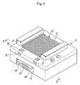
- Figure 2 is an assembled perspective view of the cooking apparatus shown in Figure 1;
- Figure 3 is a sectional view taken along the line III-III of Figure 1 illustrating each pair of cooling fans and partitioning plates mounted to a heat reflecting unit; and
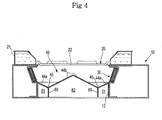
- Figure 4 is a sectional view taken along the line IV-IV of Figure 2 illustrating the rear surface of the heat reflecting unit partitioned into two side channels and a central channel by the pair of partitioning plates.
- Referring to the drawings, there is shown in Figure 1 cooking apparatus comprising a
body 10 formed in the shape of a box and having anupper opening 11 and afront opening 12, a plurality ofheating units 30 mounted to the inner sides of thebody 10 to generate heat necessary to cook food, agrill unit 20 disposed on thebody 10 such that the food can be placed thereon, and aheat reflecting unit 40 disposed under thegrill unit 20 in thebody 10 to reflect radiant heat emitted from theheating units 30 to thegrill unit 20. - The
heating units 30 are disposed on opposing sides of the interior of thebody 10 in a horizontal direction (i.e. front-to-back direction) such that fat does not fall onto theheating units 30 from food placed on thegrill unit 20 and theheating units 30 are inclined toward thegrill unit 20 to effectively transmit heat to the food. - The
grill unit 20 includes a pair ofwater buckets 21 spaced apart from each other such that thewater buckets 21 are seated onseats 13 provided on the upper surface of thebody 10 and configured to store water therein and a plurality ofgrill pipes 22, having ends connected with thewater buckets 21 such that they are filled with water. - The
heat reflecting unit 40 includes twoside plates 41 and arear plate 42, afront part 43 having a predetermined space formed therein and a heat reflecting plate 44 defined by theside plates 41, therear plate 42 and thefront part 43. - The heat reflecting plate 44 comprises a pair of first reflecting
surfaces 44a which incline downwards from the upper ends of theside plates 41 and a pair of second reflectingsurfaces 44b which incline upwards from the lower ends of the first reflectingsurfaces 44a, extending until the upper ends of the second reflectingsurfaces 44b meet each other. As a result, the heat reflecting plate 44 forms a "W" shape. - More specifically, each first reflecting
surface 44a is inclined downwards from the lower end of thecorresponding heating unit 30 and eachsecond reflecting surface 44b is inclined upward from the lower end of the corresponding first reflectingsurface 44a until eachsecond reflecting surface 44b reaches a middle position between theheating unit 30 so as to reflect heat generated from theheating units 30 to thegrill unit 20. - Also, the recesses formed between the first reflecting
surfaces 44a and the second reflectingsurfaces 44b are used asfat collection portions 45 to collect fat dropped onto the first and second reflectingsurfaces grill unit 20. - In order to prevent the temperature of the
heat reflecting unit 40 from increasing above a predetermined level due to the heat transmitted by theheating units 30, and therefore, to prevent fat falling on the heat reflecting unit 44 from being burnt, a pair ofcooling fans 50 located in fan casings are mounted in thefront part 43 of theheat reflecting unit 40 and a pair ofpartitions 60 are disposed vertically at the lower surface of the heat reflecting plate 44 in the longitudinal direction of the heat reflecting unit 40 (see Figure 4). - In order to introduce external air to the
cooling fans 50 mounted in theheat reflecting unit 40, a plurality ofcommunication holes 55 are formed through the upper part of the front surface and the front part of the upper surface of thebody 10 and a plurality ofsuction holes 56 are provided through the upper surface of thefront part 43 of theheat reflecting unit 40 facing therespective cooling fans 50. - A plurality of
discharge holes 57 are also formed through the front surface of thefront part 43 of theheat reflecting unit 40 to discharge air forcibly moved by thecooling fans 50 to cool theheat reflecting unit 40 of thebody 10. - External air is therefore introduced to the upper surface of the
front part 43 of theheat reflecting unit 40 through the front and upper parts of thebody 10 to cool theheat reflecting unit 40 and then discharged through the front surface of thefront part 43. - In order to quickly discharge air circulated through the
heat reflecting unit 40 and to prevent air circulated through theheat reflecting unit 40 from being introduced to thecooling fans 50, thebottom 14 of thebody 10 corresponding to thefront part 43 of theheat reflecting unit 40 is opened and therefore, air circulated through the interior of theheat reflecting unit 40 is also discharged through the lower part of thefront part 43. - In order to extend/retract the
heat reflecting unit 40 from/into thebody 10 through the front opening 12 in the horizontal direction such that theheat reflecting unit 40 is released from/mounted in thebody 10, agrip 46 is formed at thefront part 43 of theheat reflecting unit 40 while being protruded frontward. - Accordingly, as shown in Figure 2, when a user holds the
grip 46 of theheat reflecting unit 40 and pushes theheat reflecting unit 40 into thebody 10 through the front opening 12 in a sliding fashion, theheat reflecting unit 40 is easily mounted in thebody 10. - The heat reflecting unit cooling surface will be described hereinafter with reference to Figures 3 and 4. As shown in Figure 1, the pair of
cooling fans 50 are surrounded by thefan casings 51 and mounted in thefront part 43 of theheat reflecting unit 40. Eachfan casing 51 comprising aninlet port 51a formed in the upper part thereof and anoutlet port 51b formed in the rear part thereof. Eachcooling fan 50 may be a centrifugal fan which sucks air through the upper part of eachfan casing 51 and discharges air through the rear part of eachfan casing 51. - The pair of
partitions 60 which are disposed vertically below the lower surface of the heat reflecting plate 44, extend along the lines at which the first reflectingsurfaces 44a meet the corresponding second reflectingsurfaces 44b. The rear ends of thepartitions 60 are spaced apart from therear plate 42 of theheat reflecting unit 40. - At the lower surface of the heat reflecting plate 44 the
partitions 60 form a pair ofside channels 61 and acentral channel 62 which communicate with one another at the rear end of the heat reflecting plate 44. Eachfan casing 51, in which thecorresponding cooling fan 50 is mounted, is disposed in front of thecorresponding side channel 61 while theoutlet port 51b faces thecorresponding side channel 61. - Consequently, air forcibly blown by the
respective cooling fans 50 flows along theside channels 61 and meets at the rear end of the heat reflecting plate 44 where the flow direction of the air is changed and the air then flows along thecentral channel 62. - The
cooling fans 50 may be designed such that thecooling fans 50 are automatically operated or stopped based on whether the cooking apparatus is operated or not. Alternatively,temperature sensors 70 may be attached to the lower surface of the heat reflecting plate 44 such that thecooling fans 50 are automatically operated when the temperature of the heat reflecting plate 44 increases to a level high enough to burn fat on the heat reflecting plate 44 and thecooling fans 50 are automatically stopped when the temperature of the heat reflecting plate 44 decreases to a level below which fat is burnt on the heat reflecting plate 44. - When the user puts food to be cooked on the
grill pipes 22 and operates theheating units 30 and thecooling fans 50, some of the heat generated from theheating units 30 is directly transmitted to the food, and the remainder of the heat is reflected to the food by the first reflectingsurfaces 44a and the second reflectingsurfaces 44b to thereby cook the food. When the food is cooked as described above, fat drops from the food onto the first reflectingsurfaces 44a and the second reflectingsurfaces 44b and is then collected in thefat collection parts 45. - At this time, external air is introduced into the
front part 43 of theheat reflecting unit 40 through thecommunication holes 55 formed through the upper part of the front surface and the front part of the upper surface of thebody 10 and thesuction holes 56 provided at sides of the upper surface of thefront part 43 of theheat reflecting unit 40. The introduced air passes through therespective fan casings 51 and then flows to the rear of theheat reflecting unit 40 along theside channels 61 to cool the respective first reflectingsurfaces 44a of the heat reflecting plate 44 adjacent to therespective heating units 30. - The air having passed through the
respective side channels 61 is gathered at the rear end of theheat reflecting unit 40 wherein the flow direction of the air is changed and then flows forward along thecentral channel 62 to cool the second reflectingsurfaces 44b of the heat reflecting plate 44. - Some of the air having passed through the
central channel 62 is discharged out of thebody 10 through thedischarge holes 57 formed at the front surface of thefront part 43 of theheat reflecting unit 40 and the remainder of the air is discharged out of thebody 10 through the lower part of thefront part 43. - External air continuously circulates in the
heat reflecting unit 40 along the above mentioned channels to cool theheat reflecting unit 40. - The
communication holes 55 provided to introduce external air are spaced an appropriate distance from thedischarge holes 57 provided to discharge circulated air out of thebody 10. Consequently, air discharged through thedischarge holes 57 is not reintroduced through thecommunication holes 55. Also, theinlet ports 51a of thefan casings 51 are close to thesuction holes 56 provided at the upper surface of thefront part 43 of theheat reflecting unit 40 and therefore air having flowed from thecentral channel 62 to thefront part 43 is not reintroduced to thecooling fan 50. - The external air flows along both sides of the
heat reflecting unit 40 and then flows along the centre of theheat reflecting unit 40 by thecooling fans 50 and thepartitions 60. As a result, a sufficient amount of air is uniformly supplied to the entire surface of theheat reflecting unit 40 and therefore theheat reflecting unit 40 is effectively cooled. - The temperature of the first reflecting
surfaces 44a of theheat reflecting unit 40 adjacent to theheating units 30 may be locally increased to a higher level than that of the second reflectingsurfaces 44b of theheat reflecting unit 40 away from theheating units 30. However, external air flows along the first reflectingsurfaces 44a and then flows along the second reflectingsurfaces 44b. The temperature of the first reflectingsurfaces 44a is therefore prevented from locally increasing and therefore fat is prevented from being burnt due to the local increase of temperature at the first reflectingsurfaces 44a. - Although an embodiment of the present invention has been shown and described, it will be appreciated by those skilled in the art that this is a preferred embodiment only and changes may be made to this embodiment without departing from the principles of the invention, the scope of which is defined in the claims and their equivalents and the foregoing description should be regarded as a description of a preferred embodiment only.
Claims (19)
- Apparatus for cooking food comprising a housing having a grill to receive food to be cooked, a heat-reflecting element disposed beneath the grill to reflect heat generated by a heater adjacent to the heat-reflecting element towards the food and at least one fan for cooling the heat reflecting element, characterised by an airflow path in the housing adjacent to the heat-reflecting element so that, when the fan is operational, air flows through the airflow path to cool the heat-reflecting element.
- Apparatus according to claim 1, wherein the heat-reflecting element extends between heaters and the heat-reflecting element comprises an outer portion adjacent to each heater and, a central portion extending between each outer portion, a fan being associated with each outer portion of the heat-reflecting element for directing air over said outer portions of the heat-reflecting element.
- Apparatus according to claim 2, wherein the heat reflective element comprises a pair of baffles to separate the airflow path into an upstream airflow channel beneath each outer portions of the heat-reflective element and, a downstream airflow path beneath the central portion of the heat reflective element.
- Apparatus according to claim 3, wherein the housing has an end wall and each baffle terminates short of the end wall to allow air that has flowed along the upstream flow path beneath the outer portions of the heat reflective element to flow into the downstream flow path beneath the central portion of the heat reflective element.
- Apparatus according to claim 3 or 4, wherein each baffle depends downwardly from a point between where the outer portions and central portion of the heat-reflective element meet each other.
- Apparatus according to claim 4, wherein each outer portion meets the central portion at an angle to form a trough to collect fat and food particles therein.
- A cooking apparatus comprising a body, a grill unit disposed on the body, a plurality of heating units mounted at sides of an interior of the body, facing the grill unit and a heat reflecting unit disposed under the grill unit in the body to reflect heat generated from the heating units to the grill unit wherein the heat reflecting unit comprises a pair of cooling fans mounted therein to enable air to flow along the side surfaces thereof adjacent to the respective heating units.
- The cooking apparatus according to claim 7 wherein the heat reflecting unit comprises side plates and a rear plate, a front part having a predetermined space formed therein and a heat reflecting plate comprising a pair of first reflecting surfaces extending from upper ends of the side plates while being inclined downward respectively and a pair of second reflecting surfaces extending from lower ends of the first reflecting surfaces while being inclined upward respectively until the upper ends of the second reflecting surfaces meet each other and wherein the cooling fans are disposed to forcibly blow air toward the respective first reflecting surfaces.
- The cooking apparatus according to claim 8 wherein the heat reflecting unit further comprises a pair of partitions to partition the first reflecting surfaces from the second reflecting surfaces respectively and wherein the heat reflecting unit comprises two side channels to allow air forcibly blown by the respective cooling fans to flow from a front to a rear of the heat reflecting unit along sides thereof respectively and a central channel to allow the air to flow from the rear to the front of the heat reflecting unit along a centre thereof.
- The cooking apparatus according to claim 8 further comprising a plurality of fan casings, wherein each of the cooling fans is mounted in a respective fan casing and each fan casing comprising an inlet port formed at an upper part thereof and an outlet port formed at a rear part thereof, and wherein the front part includes a plurality of suction holes formed at both sides of the upper surface thereof, and a plurality of discharge holes formed at a center of the front surface thereof, wherein air is introduced through the upper surface of the front part, to cool the heat reflecting plate and the air is then discharged through the front surface of the front part.
- The cooking apparatus according to claim 10 wherein the body comprises a plurality of communication holes formed at the upper part of the front surface thereof, and the communication holes communicating with the suction holes such that the air is introduced into the suction holes through the communication holes in front of the body.
- The cooking apparatus according to claim 10 wherein each of the cooling fans is of a centrifugal fan.
- The cooking apparatus according to claim 9 wherein the body comprises a front opening formed at the front surface thereof, through which the heat reflecting unit is slidably released from/mounted into the body, and wherein a bottom of the body corresponding to the front part of the heat reflecting unit, is opened such that air circulated through an interior of the heat reflecting unit is discharged through a lower part of the front part.
- The cooking apparatus according to claim 8 further comprising recesses formed between the first reflecting surfaces and the second reflecting surfaces, respectively, by the inclined structure of the first reflecting surfaces and the second reflecting surfaces, the recesses serving as fat collection parts to collect fat dropped from food placed on the grill unit.
- A cooking apparatus comprising a body, a grill unit disposed on the body, a plurality of heating units mounted at sides of an interior of the body while being inclined toward the grill unit, a heat reflecting unit disposed under the grill unit in the body, wherein the heat reflecting unit comprises a pair of partitions disposed in the longitudinal direction thereof while being opposite to the heating units, respectively, such that an interior of the heat reflecting unit is partitioned into a pair of side channels and a central channel by the partitions and cooling fans mounted in front of the side channels, respectively, to cool the heat reflecting unit.
- The cooking apparatus according to claim 15 wherein the heat reflecting unit has a plurality of suction holes, which are provided above the cooling fans, and the heat reflecting unit has a plurality of discharge holes formed at the center of the front surface thereof.
- The cooking apparatus according to claim 16 further comprising fat collection parts provided at the sides of the upper surface of the heat reflecting unit to collect fat dropped from food placed on the grill unit.
- The cooking apparatus of claim 7, further comprising temperature sensors attached at a lower surface of the heat reflecting unit to sense the temperature of the heat reflecting unit, wherein the cooling fans automatically operate when the temperature of the heat reflecting unit increases above the predetermined level.
- The cooking apparatus of claim 15 further comprising temperature sensors attached at a lower surface of the heat reflecting unit to sense the temperature of the heat reflecting unit, wherein the cooling fans automatically operate when the temperature of the heat reflecting unit increases above the predetermined level.
Applications Claiming Priority (1)
| Application Number | Priority Date | Filing Date | Title |
|---|---|---|---|
| KR1020050004717A KR20060083780A (en) | 2005-01-18 | 2005-01-18 | Cooking device |
Publications (2)
| Publication Number | Publication Date |
|---|---|
| EP1680997A2 true EP1680997A2 (en) | 2006-07-19 |
| EP1680997A3 EP1680997A3 (en) | 2008-11-12 |
Family
ID=35985888
Family Applications (1)
| Application Number | Title | Priority Date | Filing Date |
|---|---|---|---|
| EP05107758A Withdrawn EP1680997A3 (en) | 2005-01-18 | 2005-08-24 | Cooking apparatus |
Country Status (3)
| Country | Link |
|---|---|
| US (1) | US20060157046A1 (en) |
| EP (1) | EP1680997A3 (en) |
| KR (1) | KR20060083780A (en) |
Cited By (2)
| Publication number | Priority date | Publication date | Assignee | Title |
|---|---|---|---|---|
| CN104665611A (en) * | 2013-12-02 | 2015-06-03 | 新玛德制造厂有限公司 | Baking tray and oil smoke treatment method of baking tray |
| EP3287702B1 (en) * | 2011-04-28 | 2019-09-18 | Wilhelm Bruckbauer | Hotplate and steam extractor |
Families Citing this family (9)
| Publication number | Priority date | Publication date | Assignee | Title |
|---|---|---|---|---|
| CN101569509B (en) * | 2008-04-28 | 2011-02-09 | 上海酒店设备工程成套南翔厂有限公司 | Heat insulating device of dumpling frying furnace |
| WO2015185282A1 (en) * | 2014-06-06 | 2015-12-10 | Arcelik Anonim Sirketi | A cooking device with smoking function |
| US10638879B2 (en) | 2015-06-11 | 2020-05-05 | Whirlpool Corporation | Grilling appliance having air jacket for smoke removal and ventilation |
| US10716434B2 (en) * | 2018-07-10 | 2020-07-21 | Richard John Fitzgerald | System for cleaning and enclosed bar-b-que |
| EP3868265A1 (en) * | 2020-02-19 | 2021-08-25 | BaByliss Faco sprl | Cooking device |
| KR20210115329A (en) * | 2020-03-12 | 2021-09-27 | 엘지전자 주식회사 | Electric range |
| JP7400606B2 (en) * | 2020-04-06 | 2023-12-19 | 三菱電機株式会社 | Inverter circuit board cooling structure and induction heating cooker |
| JP7380395B2 (en) * | 2020-04-06 | 2023-11-15 | 三菱電機株式会社 | Induction heating cooker, built-in complex heating cooker, and kitchen furniture |
| TR202016787A2 (en) * | 2020-10-21 | 2022-05-23 | Vestel Beyaz Esya San Ve Tic A S | A cooking appliance with a smoker function. |
Family Cites Families (3)
| Publication number | Priority date | Publication date | Assignee | Title |
|---|---|---|---|---|
| JPS61105036A (en) * | 1984-10-29 | 1986-05-23 | Matsushita Electric Ind Co Ltd | cooking unit |
| KR20040071023A (en) * | 2003-02-06 | 2004-08-11 | 삼성전자주식회사 | Cooking Unit |
| KR20050026610A (en) * | 2003-09-09 | 2005-03-15 | 삼성전자주식회사 | Grill cooker and complex cooking apparatus having the grill cooker |
-
2005
- 2005-01-18 KR KR1020050004717A patent/KR20060083780A/en not_active Withdrawn
- 2005-08-16 US US11/204,094 patent/US20060157046A1/en not_active Abandoned
- 2005-08-24 EP EP05107758A patent/EP1680997A3/en not_active Withdrawn
Cited By (3)
| Publication number | Priority date | Publication date | Assignee | Title |
|---|---|---|---|---|
| EP3287702B1 (en) * | 2011-04-28 | 2019-09-18 | Wilhelm Bruckbauer | Hotplate and steam extractor |
| US12339011B2 (en) | 2011-04-28 | 2025-06-24 | Werkhaus GmbH & Co. KG | Hob with central downward removal of cooking vapors through suction |
| CN104665611A (en) * | 2013-12-02 | 2015-06-03 | 新玛德制造厂有限公司 | Baking tray and oil smoke treatment method of baking tray |
Also Published As
| Publication number | Publication date |
|---|---|
| KR20060083780A (en) | 2006-07-21 |
| US20060157046A1 (en) | 2006-07-20 |
| EP1680997A3 (en) | 2008-11-12 |
Similar Documents
| Publication | Publication Date | Title |
|---|---|---|
| US5361686A (en) | Rotisserie oven | |
| US5451744A (en) | Rotisserie oven | |
| US7210402B2 (en) | Cooking apparatus | |
| EP1680997A2 (en) | Cooking apparatus | |
| CA2202954C (en) | Low moisture/closed door broil oven ventilation system | |
| JP7181088B2 (en) | Gas fryer and method with uniform heat exchange and improved cleaning access | |
| US20190298106A1 (en) | An air-based cooker | |
| EP3725192B1 (en) | Device for storing food products at hot temperature | |
| US7150220B2 (en) | Cooking apparatus having a contamination preventing unit | |
| JP6382153B2 (en) | Cooker | |
| EP1444938B1 (en) | Grill unit and cooking apparatus with the same | |
| JP2016217572A (en) | Heating cooker | |
| EP1680995A1 (en) | Cooking apparatus | |
| CN216907659U (en) | Air fryer | |
| KR20000005628A (en) | Grill device | |
| GB2132338A (en) | Oven with air circulation | |
| KR20190084661A (en) | brazier for cooking | |
| KR0132999Y1 (en) | Cooling apparatus of oven range | |
| KR200141514Y1 (en) | Cooling apparatus of door in a oven range | |
| JP6730081B2 (en) | Continuous rice cooker | |
| EP1444934B1 (en) | Grill unit and cooking apparatus with the same | |
| CN216534973U (en) | Cooking device with air frying function | |
| CN216652082U (en) | Fry basket structure and cooking equipment thereof | |
| JP2006003030A (en) | Cooker | |
| KR100588161B1 (en) | Grill device |
Legal Events
| Date | Code | Title | Description |
|---|---|---|---|
| PUAI | Public reference made under article 153(3) epc to a published international application that has entered the european phase |
Free format text: ORIGINAL CODE: 0009012 |
|
| AK | Designated contracting states |
Kind code of ref document: A2 Designated state(s): AT BE BG CH CY CZ DE DK EE ES FI FR GB GR HU IE IS IT LI LT LU LV MC NL PL PT RO SE SI SK TR |
|
| AX | Request for extension of the european patent |
Extension state: AL BA HR MK YU |
|
| PUAL | Search report despatched |
Free format text: ORIGINAL CODE: 0009013 |
|
| AK | Designated contracting states |
Kind code of ref document: A3 Designated state(s): AT BE BG CH CY CZ DE DK EE ES FI FR GB GR HU IE IS IT LI LT LU LV MC NL PL PT RO SE SI SK TR |
|
| AX | Request for extension of the european patent |
Extension state: AL BA HR MK YU |
|
| AKX | Designation fees paid | ||
| STAA | Information on the status of an ep patent application or granted ep patent |
Free format text: STATUS: THE APPLICATION IS DEEMED TO BE WITHDRAWN |
|
| REG | Reference to a national code |
Ref country code: DE Ref legal event code: 8566 |
|
| 18D | Application deemed to be withdrawn |
Effective date: 20090303 |