EP1679477B1 - Blade-holder & bearing for an adjustable louvre system featuring high torque characteristics - Google Patents
Blade-holder & bearing for an adjustable louvre system featuring high torque characteristics Download PDFInfo
- Publication number
- EP1679477B1 EP1679477B1 EP05257153A EP05257153A EP1679477B1 EP 1679477 B1 EP1679477 B1 EP 1679477B1 EP 05257153 A EP05257153 A EP 05257153A EP 05257153 A EP05257153 A EP 05257153A EP 1679477 B1 EP1679477 B1 EP 1679477B1
- Authority
- EP
- European Patent Office
- Prior art keywords
- blade
- holder
- bearing
- socket
- male
- Prior art date
- Legal status (The legal status is an assumption and is not a legal conclusion. Google has not performed a legal analysis and makes no representation as to the accuracy of the status listed.)
- Expired - Lifetime
Links
Images


Classifications
-
- E—FIXED CONSTRUCTIONS
- E06—DOORS, WINDOWS, SHUTTERS, OR ROLLER BLINDS IN GENERAL; LADDERS
- E06B—FIXED OR MOVABLE CLOSURES FOR OPENINGS IN BUILDINGS, VEHICLES, FENCES OR LIKE ENCLOSURES IN GENERAL, e.g. DOORS, WINDOWS, BLINDS, GATES
- E06B7/00—Special arrangements or measures in connection with doors or windows
- E06B7/02—Special arrangements or measures in connection with doors or windows for providing ventilation, e.g. through double windows; Arrangement of ventilation roses
- E06B7/08—Louvre doors, windows or grilles
- E06B7/084—Louvre doors, windows or grilles with rotatable lamellae
- E06B7/086—Louvre doors, windows or grilles with rotatable lamellae interconnected for concurrent movement
-
- F—MECHANICAL ENGINEERING; LIGHTING; HEATING; WEAPONS; BLASTING
- F24—HEATING; RANGES; VENTILATING
- F24F—AIR-CONDITIONING; AIR-HUMIDIFICATION; VENTILATION; USE OF AIR CURRENTS FOR SCREENING
- F24F13/00—Details common to, or for air-conditioning, air-humidification, ventilation or use of air currents for screening
- F24F13/08—Air-flow control members, e.g. louvres, grilles, flaps or guide plates
- F24F13/10—Air-flow control members, e.g. louvres, grilles, flaps or guide plates movable, e.g. dampers
- F24F13/14—Air-flow control members, e.g. louvres, grilles, flaps or guide plates movable, e.g. dampers built up of tilting members, e.g. louvre
- F24F13/1486—Air-flow control members, e.g. louvres, grilles, flaps or guide plates movable, e.g. dampers built up of tilting members, e.g. louvre characterised by bearings, pivots or hinges
Definitions
- the invention relates to a blade holder and bearing assembly to be incorporated in louver systems of the type having adjustable blades, which features high strength against torque loads and ease of assembly in the manufacturing process, such a blade holder and bearing is known from US 4 643 081 A which discloses the preamble of claim 1.
- connecting rods are loosely riveted on the bearings so as to allow the relative movement of the one against the other.
- the vertical movement of the connecting rods is translated into rotational motion on the bearing. Since each bearing is joined with a corresponding blade-holder and the latter holds the blade axial rotation of the blades is achieved.
- the vertical movement of the bars, which results in the rotation of the blades, is usually achieved via a worm gear system or via a linkage mechanism that is connected to a handle. An illustration of such a system is found in Fig 1 .
- the first drawback relates to the relatively low value of the maximum torque characteristics of the system. Since the movement of the blades originates from the vertical movement of the connecting rods, which in turn drive, the bearing, which is jointed on the blade-holder, this means that to a large extent the torque characteristics of the system are limited by the strength of the blade-holder and bearing joint.
- the blade-holder and bearing joint is achieved via a male polygon member being inserted inside a female polygon socket and a clip mechanism that stops them from sliding against each other after the insertion has occurred.
- the male polygon member is part of the blade-holder and the female polygon socket is part of the bearing and in other joints the other way round.
- the blade-holder and bearing torque characteristics are limited by the material flexibility of the male polygon member and/or the female socket, which is inherently low since either one of them or both of them are made of a synthetic material which needs to posses good flexibility characteristics so as to serve other design purposes such as the clip mechanism and blade holding.
- the second drawback originates from the fact that it is technically difficult to assemble the bearing with the blade-holder. This is because prior to the assembly the bearing and the blade-holder have to be properly aligned on top of each other. In the current state of the art this is technically difficult to achieve without the requirement of special purpose assembly machines due to the inherent design of the clip mechanism that gets in the way and does not allow the ease of orientation of the blade-holder on the bearing prior to the insertion to form the joint.
- louver systems are required in numerous sizes depending on the window size it is very difficult and costly to keep adequate stocks on an international basis to serve each local market. For this to be carried out economically and efficiently the assembly of the mechanisms must be performed locally to each market. However this requires the setup of special assembly machines at each site, which is technically difficult to maintain.
- the object of this invention described herein is that of eliminating the drawbacks outlined.
- the stated object is realized with a blade-holder and bearing as described in the following specification and as characterized in the appended claims that fits common types of louver systems as described earlier and allows a high torque joint of the blade-holder on the bearing which is easy to assemble without the need of special machines or time consuming manual operations.
- the key to this invention is the simplicity in terms of design, construction and assembly that results in lowering the cost of investment and production.
- this invention provides a blade-holder consisting of a blade socket on the one side and on the other side a central male polygon member with chamfered tip equipped with guiding grooves leading to ramps followed by two openings that reveal catches, surrounded by a female polygonal socket.
- bearing characterized by a circular plate consisting on the one side two projecting pins and on the other side a central female polygon socket surrounded by a male polygon member part of which consists of two projecting flexible legs equipped with hooks.
- the blade-holder and the bearing are made out of a plastics material but the blade-holder may instead be made from a rigid material such as metal.
- Fig. 1 provides an illustration of a typical louver system with adjustable blades, which is limited to a pair of U-shaped members 1, a blades 2 with respective blade-holders 3, bearings 4 and two connecting rods 9.
- each U-shaped member 1 there are a series of holes 5 at constant intervals that are used for holding the blade-holder 3 and bearing 4 assembly which in turn is used to hold the blade 2. So in effect when placing a set of U-shaped members 1 facing each other with the blade-holder 3 and bearing 1 assemblies completed, the blades 2 can be located in the blade-holders 3 thus creating an adjustable louver system.
- the blades 2 in the example illustrated are made out of extruded aluminum but that does not have to be the case. They could be made out of a plastics material, wood, glass or any other rigid material.
- the top part of the blade-holder 3 consists of a blade socket 28 which is similarly shaped as the blades 2 to allow a tight fit, which can be secured via a clip mechanism.
- each bearing 4 two pins 8 are projecting which are used for engaging the connecting rods 9 and are locked via a riveting operation 10.
- a collar is formed 11 that is marginally less than the hole 5 in the U-shaped member 1 thus allowing the blade-holder and bearing assembly to freely rotate in respect with the U-shaped member 1.
- This rotation is generated via the linear movement of the connecting rods 9.
- the linear movement of the connecting rods 9 can be generated via a worm gear mechanism or a linkage mechanism connected to a lever.
- FIG. 2 shows top and bottom views of a blade-holder according to the invention. It is important to note that this blade-holder consists of a central male component 14, a perimeter female socket 13 and a set of alignment guides 20 leading to a set of openings 21 that reveal a set of inclined clip seats. Note that in this illustration the male components and female sockets are in a quadrangular configuration but this innovation is not restricted to only this type of polygon.
- FIG. 3 shows top and bottom views of a bearing 4 according to the invention. It is important to note that the illustrated bearing is essentially a circular plate consisting on the one side two projecting pins 8 and on the other side a central female polygon socket 22 surrounded by a male polygon member 23 part of which consists of two projecting flexible legs 24 equipped with hooks 26.
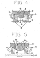
- Figure 4 shows a section of the bearing 4 and a section of the lower part of the blade-holder 3 in an assembly configuration on a U-shaped member 1 forming a high strength joint.
- the bearing 4 male polygon element 23 engages in the blade-holder 3 female polygon socket 13 and also the bearing 4 female polygon socket 22 engages in the blade-holder 3 male polygon element 14, thus forming a high torque joint.
- This type of joint can withstand much greater torques than current state of the art blade-holder and bearing joints.
- the blade-holder 3 and the bearing 4 have either a male or a female component. They do not have both.
- Figure 5 shows another section view of the bearing 4 and section view of the lower part of the blade-holder 3 in an assembled configuration on U-shaped frame 1 forming a high strength joint with emphasis on the clip mechanism.
- the two legs 24 bend outward to allow the blade-holder 3 central section 14 to locate itself below the legs 24.
- Each leg is equipped with a lip 25 which part of it forms a catch 26 that will anchor on the blade-holder 3 central section part 27 in case an attempt is made to disengage the blade-holder 3 from the bearing 4 or slide the one against the other.
- Figure 6 shows the way in which the bearing 4 is freely aligned against the blade-holder 3 prior to the application of pressure to achieve the insertion of the one into the other.
- the legs 24 slide along guides 20 provided by the blade-holder 3 with adequate clearance to allow free movement and self alignment. Having moved a certain distance the blade-holder 3 reaches a point where its male component 14 forms a tight fit with the bearing socket 22 and as a result requires additional pressure to move forward. At this point the bearing 4 sits aligned with respect to the blade-holder 3 and is ready to be inserted either by hand or via an automatic pressure device.
Landscapes
- Engineering & Computer Science (AREA)
- General Engineering & Computer Science (AREA)
- Structural Engineering (AREA)
- Chemical & Material Sciences (AREA)
- Combustion & Propulsion (AREA)
- Mechanical Engineering (AREA)
- Civil Engineering (AREA)
- Specific Sealing Or Ventilating Devices For Doors And Windows (AREA)
- Blinds (AREA)
- Operating, Guiding And Securing Of Roll- Type Closing Members (AREA)
- Magnetic Bearings And Hydrostatic Bearings (AREA)
- Support Of The Bearing (AREA)
- Curtains And Furnishings For Windows Or Doors (AREA)
Priority Applications (1)
| Application Number | Priority Date | Filing Date | Title |
|---|---|---|---|
| CY20081100550T CY1107970T1 (el) | 2005-01-07 | 2008-05-26 | Στηριγμα πτερυγιου και εδρανο για συστημα ρυθμιζομενων κινητων περσιδων που διαθετει χαρακτηριστικα υψηλης ροπης στρεψης |
Applications Claiming Priority (1)
| Application Number | Priority Date | Filing Date | Title |
|---|---|---|---|
| CY0500002A CY2518B1 (enExample) | 2005-01-07 | 2005-01-07 |
Publications (2)
| Publication Number | Publication Date |
|---|---|
| EP1679477A1 EP1679477A1 (en) | 2006-07-12 |
| EP1679477B1 true EP1679477B1 (en) | 2008-04-30 |
Family
ID=38729081
Family Applications (1)
| Application Number | Title | Priority Date | Filing Date |
|---|---|---|---|
| EP05257153A Expired - Lifetime EP1679477B1 (en) | 2005-01-07 | 2005-11-21 | Blade-holder & bearing for an adjustable louvre system featuring high torque characteristics |
Country Status (6)
| Country | Link |
|---|---|
| EP (1) | EP1679477B1 (enExample) |
| AT (1) | ATE393902T1 (enExample) |
| CY (2) | CY2518B1 (enExample) |
| DE (1) | DE602005006373D1 (enExample) |
| ES (1) | ES2303200T3 (enExample) |
| PT (1) | PT1679477E (enExample) |
Families Citing this family (4)
| Publication number | Priority date | Publication date | Assignee | Title |
|---|---|---|---|---|
| ITBO20110491A1 (it) * | 2011-08-05 | 2013-02-06 | Nuova Eurosystem S R L | Gruppo per il montaggio di stecche orientabili al telaio di un'anta di una persiana |
| KR101636504B1 (ko) * | 2015-06-18 | 2016-07-05 | (주)미도이앤씨 | 배연댐퍼 개폐장치 |
| ITUA20162994A1 (it) * | 2016-04-29 | 2017-10-29 | I Quattro S R L | Gruppo persiana comprendente un dispositivo di movimentazione di lamelle della persiana. |
| CN108131086B (zh) * | 2018-01-22 | 2023-11-24 | 清远市首一建筑新材料有限公司 | 一种百叶窗的百叶夹 |
Family Cites Families (5)
| Publication number | Priority date | Publication date | Assignee | Title |
|---|---|---|---|---|
| GB1042731A (en) * | 1961-12-05 | 1966-09-14 | Beta Aluminium Products Ltd | Adjustable louvre windows or shutters |
| IT1182740B (it) * | 1985-06-05 | 1987-10-05 | Pillar Naco Ind | Struttura, a lamelle inclinabili ed orientabili, con clips portalamelle modulari e sfilabili |
| IT224867Z2 (it) * | 1989-12-12 | 1996-07-26 | Sergio Torresi | Supporto di estremita' e manovella di movimentazione,in materiale pla stico o simile,per lamelle o stecche orientabili,ad inserimento diretto e rapido su intelaiature premontate per serramenti a persiana. |
| NZ248949A (en) * | 1993-10-14 | 1997-09-22 | Interlock Ind Ltd | A mount for a louvre pane has raised sealing devices on both ends which interfit with adjacent mounts when in a closed position |
| US5794380A (en) * | 1997-01-24 | 1998-08-18 | Reflectolite Products Company, Inc. | Louvre window clip assembly |
-
2005
- 2005-01-07 CY CY0500002A patent/CY2518B1/xx unknown
- 2005-11-21 AT AT05257153T patent/ATE393902T1/de not_active IP Right Cessation
- 2005-11-21 ES ES05257153T patent/ES2303200T3/es not_active Expired - Lifetime
- 2005-11-21 DE DE602005006373T patent/DE602005006373D1/de not_active Expired - Lifetime
- 2005-11-21 PT PT05257153T patent/PT1679477E/pt unknown
- 2005-11-21 EP EP05257153A patent/EP1679477B1/en not_active Expired - Lifetime
-
2008
- 2008-05-26 CY CY20081100550T patent/CY1107970T1/el unknown
Also Published As
| Publication number | Publication date |
|---|---|
| PT1679477E (pt) | 2008-06-06 |
| DE602005006373D1 (de) | 2008-06-12 |
| ATE393902T1 (de) | 2008-05-15 |
| CY2518B1 (enExample) | 2006-02-08 |
| EP1679477A1 (en) | 2006-07-12 |
| ES2303200T3 (es) | 2008-08-01 |
| CY1107970T1 (el) | 2013-09-04 |
Similar Documents
| Publication | Publication Date | Title |
|---|---|---|
| US9422715B1 (en) | Louvered roof apparatus and control system | |
| JP4005148B2 (ja) | 遮蔽装置用支持手段 | |
| US8474187B2 (en) | Shutter with removable louvres | |
| US4268995A (en) | Window frames having swingable blind-slats | |
| EP1679477B1 (en) | Blade-holder & bearing for an adjustable louvre system featuring high torque characteristics | |
| KR100966170B1 (ko) | 환기창용 셔터개폐장치 | |
| JP6824546B1 (ja) | ヒンジ及び扉機構 | |
| KR102087666B1 (ko) | 날개의 탈부착이 가능한 루버시스템 | |
| EP3009728A1 (de) | Sicherungselement für Stativvorrichtung sowie dazu korrespondierend ausgebildete Komponenten | |
| EP3269881B1 (en) | Gate board tightening device | |
| KR101280822B1 (ko) | 에어컨 실외기실용 루버 개폐장치 | |
| EP2093493B1 (de) | Hausgerätvorrichtung | |
| EP1048816B1 (en) | An apparatus and method for connecting profiled elements in conditions of mutual co-planarity and unity, in the manufacture of planar frames | |
| CN208185948U (zh) | 一种拼接灯具 | |
| CN222228428U (zh) | 窗帘免打孔电动安装装置及其顶梁安装组件 | |
| CN108952441A (zh) | 一种推拉式门窗的自动化与手动无切换开关活动扇装置 | |
| CN116464336B (zh) | 一种把手 | |
| KR101662612B1 (ko) | 블라인드의 길이 조절장치 | |
| CN115263168B (zh) | 百叶窗调光器 | |
| CN223423523U (zh) | 一种方便快捷安装的天棚帘 | |
| CN118346157A (zh) | 窗帘免打孔电动安装装置及其顶梁安装组件 | |
| KR100484089B1 (ko) | 루버시스템 작동 장치 | |
| CN214007620U (zh) | 一种风机固定装置及应用有该风机固定装置的吸油烟机 | |
| KR102628883B1 (ko) | 루버 개폐장치 | |
| US224908A (en) | Andrew l |
Legal Events
| Date | Code | Title | Description |
|---|---|---|---|
| PUAI | Public reference made under article 153(3) epc to a published international application that has entered the european phase |
Free format text: ORIGINAL CODE: 0009012 |
|
| AK | Designated contracting states |
Kind code of ref document: A1 Designated state(s): AT BE BG CH CY CZ DE DK EE ES FI FR GB GR HU IE IS IT LI LT LU LV MC NL PL PT RO SE SI SK TR |
|
| AX | Request for extension of the european patent |
Extension state: AL BA HR MK YU |
|
| 17P | Request for examination filed |
Effective date: 20070102 |
|
| AKX | Designation fees paid |
Designated state(s): AT BE BG CH CY CZ DE DK EE ES FI FR GB GR HU IE IS IT LI LT LU LV MC NL PL PT RO SE SI SK TR |
|
| GRAP | Despatch of communication of intention to grant a patent |
Free format text: ORIGINAL CODE: EPIDOSNIGR1 |
|
| GRAS | Grant fee paid |
Free format text: ORIGINAL CODE: EPIDOSNIGR3 |
|
| GRAA | (expected) grant |
Free format text: ORIGINAL CODE: 0009210 |
|
| AK | Designated contracting states |
Kind code of ref document: B1 Designated state(s): AT BE BG CH CY CZ DE DK EE ES FI FR GB GR HU IE IS IT LI LT LU LV MC NL PL PT RO SE SI SK TR |
|
| REG | Reference to a national code |
Ref country code: GB Ref legal event code: FG4D |
|
| REG | Reference to a national code |
Ref country code: CH Ref legal event code: EP |
|
| REG | Reference to a national code |
Ref country code: PT Ref legal event code: SC4A Free format text: AVAILABILITY OF NATIONAL TRANSLATION Effective date: 20080527 |
|
| REG | Reference to a national code |
Ref country code: IE Ref legal event code: FG4D Free format text: LANGUAGE OF EP DOCUMENT: FRENCH |
|
| REF | Corresponds to: |
Ref document number: 602005006373 Country of ref document: DE Date of ref document: 20080612 Kind code of ref document: P |
|
| REG | Reference to a national code |
Ref country code: RO Ref legal event code: EPE |
|
| REG | Reference to a national code |
Ref country code: GR Ref legal event code: EP Ref document number: 20080401561 Country of ref document: GR |
|
| REG | Reference to a national code |
Ref country code: CH Ref legal event code: PK Free format text: DAS PRIORITAETSAKTENZEICHEN WURDE BERICHTIGT: |
|
| REG | Reference to a national code |
Ref country code: ES Ref legal event code: FG2A Ref document number: 2303200 Country of ref document: ES Kind code of ref document: T3 |
|
| PG25 | Lapsed in a contracting state [announced via postgrant information from national office to epo] |
Ref country code: SI Free format text: LAPSE BECAUSE OF FAILURE TO SUBMIT A TRANSLATION OF THE DESCRIPTION OR TO PAY THE FEE WITHIN THE PRESCRIBED TIME-LIMIT Effective date: 20080430 |
|
| NLV1 | Nl: lapsed or annulled due to failure to fulfill the requirements of art. 29p and 29m of the patents act | ||
| PG25 | Lapsed in a contracting state [announced via postgrant information from national office to epo] |
Ref country code: FI Free format text: LAPSE BECAUSE OF FAILURE TO SUBMIT A TRANSLATION OF THE DESCRIPTION OR TO PAY THE FEE WITHIN THE PRESCRIBED TIME-LIMIT Effective date: 20080430 Ref country code: NL Free format text: LAPSE BECAUSE OF FAILURE TO SUBMIT A TRANSLATION OF THE DESCRIPTION OR TO PAY THE FEE WITHIN THE PRESCRIBED TIME-LIMIT Effective date: 20080430 |
|
| PG25 | Lapsed in a contracting state [announced via postgrant information from national office to epo] |
Ref country code: AT Free format text: LAPSE BECAUSE OF FAILURE TO SUBMIT A TRANSLATION OF THE DESCRIPTION OR TO PAY THE FEE WITHIN THE PRESCRIBED TIME-LIMIT Effective date: 20080430 Ref country code: PL Free format text: LAPSE BECAUSE OF FAILURE TO SUBMIT A TRANSLATION OF THE DESCRIPTION OR TO PAY THE FEE WITHIN THE PRESCRIBED TIME-LIMIT Effective date: 20080430 Ref country code: LV Free format text: LAPSE BECAUSE OF FAILURE TO SUBMIT A TRANSLATION OF THE DESCRIPTION OR TO PAY THE FEE WITHIN THE PRESCRIBED TIME-LIMIT Effective date: 20080430 |
|
| PG25 | Lapsed in a contracting state [announced via postgrant information from national office to epo] |
Ref country code: IS Free format text: LAPSE BECAUSE OF FAILURE TO SUBMIT A TRANSLATION OF THE DESCRIPTION OR TO PAY THE FEE WITHIN THE PRESCRIBED TIME-LIMIT Effective date: 20080830 |
|
| PG25 | Lapsed in a contracting state [announced via postgrant information from national office to epo] |
Ref country code: SE Free format text: LAPSE BECAUSE OF FAILURE TO SUBMIT A TRANSLATION OF THE DESCRIPTION OR TO PAY THE FEE WITHIN THE PRESCRIBED TIME-LIMIT Effective date: 20080731 Ref country code: DK Free format text: LAPSE BECAUSE OF FAILURE TO SUBMIT A TRANSLATION OF THE DESCRIPTION OR TO PAY THE FEE WITHIN THE PRESCRIBED TIME-LIMIT Effective date: 20080430 Ref country code: CZ Free format text: LAPSE BECAUSE OF FAILURE TO SUBMIT A TRANSLATION OF THE DESCRIPTION OR TO PAY THE FEE WITHIN THE PRESCRIBED TIME-LIMIT Effective date: 20080430 Ref country code: LT Free format text: LAPSE BECAUSE OF FAILURE TO SUBMIT A TRANSLATION OF THE DESCRIPTION OR TO PAY THE FEE WITHIN THE PRESCRIBED TIME-LIMIT Effective date: 20080430 |
|
| EN | Fr: translation not filed | ||
| PG25 | Lapsed in a contracting state [announced via postgrant information from national office to epo] |
Ref country code: SK Free format text: LAPSE BECAUSE OF FAILURE TO SUBMIT A TRANSLATION OF THE DESCRIPTION OR TO PAY THE FEE WITHIN THE PRESCRIBED TIME-LIMIT Effective date: 20080430 Ref country code: BE Free format text: LAPSE BECAUSE OF FAILURE TO SUBMIT A TRANSLATION OF THE DESCRIPTION OR TO PAY THE FEE WITHIN THE PRESCRIBED TIME-LIMIT Effective date: 20080430 |
|
| PGFP | Annual fee paid to national office [announced via postgrant information from national office to epo] |
Ref country code: ES Payment date: 20081216 Year of fee payment: 4 Ref country code: PT Payment date: 20081031 Year of fee payment: 4 Ref country code: RO Payment date: 20081001 Year of fee payment: 4 |
|
| PLBE | No opposition filed within time limit |
Free format text: ORIGINAL CODE: 0009261 |
|
| STAA | Information on the status of an ep patent application or granted ep patent |
Free format text: STATUS: NO OPPOSITION FILED WITHIN TIME LIMIT |
|
| PGFP | Annual fee paid to national office [announced via postgrant information from national office to epo] |
Ref country code: BG Payment date: 20081112 Year of fee payment: 4 |
|
| 26N | No opposition filed |
Effective date: 20090202 |
|
| PG25 | Lapsed in a contracting state [announced via postgrant information from national office to epo] |
Ref country code: FR Free format text: LAPSE BECAUSE OF FAILURE TO SUBMIT A TRANSLATION OF THE DESCRIPTION OR TO PAY THE FEE WITHIN THE PRESCRIBED TIME-LIMIT Effective date: 20090227 Ref country code: DE Free format text: LAPSE BECAUSE OF FAILURE TO SUBMIT A TRANSLATION OF THE DESCRIPTION OR TO PAY THE FEE WITHIN THE PRESCRIBED TIME-LIMIT Effective date: 20080731 Ref country code: EE Free format text: LAPSE BECAUSE OF FAILURE TO SUBMIT A TRANSLATION OF THE DESCRIPTION OR TO PAY THE FEE WITHIN THE PRESCRIBED TIME-LIMIT Effective date: 20080430 |
|
| PG25 | Lapsed in a contracting state [announced via postgrant information from national office to epo] |
Ref country code: MC Free format text: LAPSE BECAUSE OF NON-PAYMENT OF DUE FEES Effective date: 20081130 |
|
| REG | Reference to a national code |
Ref country code: IE Ref legal event code: MM4A |
|
| PG25 | Lapsed in a contracting state [announced via postgrant information from national office to epo] |
Ref country code: IE Free format text: LAPSE BECAUSE OF NON-PAYMENT OF DUE FEES Effective date: 20081121 |
|
| REG | Reference to a national code |
Ref country code: PT Ref legal event code: MM4A Free format text: LAPSE DUE TO NON-PAYMENT OF FEES Effective date: 20100521 |
|
| REG | Reference to a national code |
Ref country code: CH Ref legal event code: PL |
|
| GBPC | Gb: european patent ceased through non-payment of renewal fee |
Effective date: 20091121 |
|
| PG25 | Lapsed in a contracting state [announced via postgrant information from national office to epo] |
Ref country code: BG Free format text: LAPSE BECAUSE OF EXPIRATION OF PROTECTION Effective date: 20100531 Ref country code: LU Free format text: LAPSE BECAUSE OF NON-PAYMENT OF DUE FEES Effective date: 20081121 Ref country code: PT Free format text: LAPSE BECAUSE OF NON-PAYMENT OF DUE FEES Effective date: 20100521 Ref country code: HU Free format text: LAPSE BECAUSE OF FAILURE TO SUBMIT A TRANSLATION OF THE DESCRIPTION OR TO PAY THE FEE WITHIN THE PRESCRIBED TIME-LIMIT Effective date: 20081101 |
|
| PG25 | Lapsed in a contracting state [announced via postgrant information from national office to epo] |
Ref country code: TR Free format text: LAPSE BECAUSE OF FAILURE TO SUBMIT A TRANSLATION OF THE DESCRIPTION OR TO PAY THE FEE WITHIN THE PRESCRIBED TIME-LIMIT Effective date: 20080430 |
|
| PG25 | Lapsed in a contracting state [announced via postgrant information from national office to epo] |
Ref country code: CH Free format text: LAPSE BECAUSE OF NON-PAYMENT OF DUE FEES Effective date: 20091130 Ref country code: LI Free format text: LAPSE BECAUSE OF NON-PAYMENT OF DUE FEES Effective date: 20091130 |
|
| PG25 | Lapsed in a contracting state [announced via postgrant information from national office to epo] |
Ref country code: GB Free format text: LAPSE BECAUSE OF NON-PAYMENT OF DUE FEES Effective date: 20091121 |
|
| PG25 | Lapsed in a contracting state [announced via postgrant information from national office to epo] |
Ref country code: RO Free format text: LAPSE BECAUSE OF NON-PAYMENT OF DUE FEES Effective date: 20091121 |
|
| REG | Reference to a national code |
Ref country code: ES Ref legal event code: FD2A Effective date: 20110309 |
|
| PG25 | Lapsed in a contracting state [announced via postgrant information from national office to epo] |
Ref country code: ES Free format text: LAPSE BECAUSE OF NON-PAYMENT OF DUE FEES Effective date: 20110308 |
|
| PG25 | Lapsed in a contracting state [announced via postgrant information from national office to epo] |
Ref country code: ES Free format text: LAPSE BECAUSE OF NON-PAYMENT OF DUE FEES Effective date: 20091122 |
|
| PGFP | Annual fee paid to national office [announced via postgrant information from national office to epo] |
Ref country code: IT Payment date: 20081130 Year of fee payment: 4 |
|
| PGFP | Annual fee paid to national office [announced via postgrant information from national office to epo] |
Ref country code: CY Payment date: 20121015 Year of fee payment: 8 |
|
| PGFP | Annual fee paid to national office [announced via postgrant information from national office to epo] |
Ref country code: GR Payment date: 20121016 Year of fee payment: 8 |
|
| REG | Reference to a national code |
Ref country code: GR Ref legal event code: ML Ref document number: 20080401561 Country of ref document: GR Effective date: 20140603 |
|
| PG25 | Lapsed in a contracting state [announced via postgrant information from national office to epo] |
Ref country code: GR Free format text: LAPSE BECAUSE OF NON-PAYMENT OF DUE FEES Effective date: 20140603 Ref country code: CY Free format text: LAPSE BECAUSE OF NON-PAYMENT OF DUE FEES Effective date: 20131121 |