EP1679477A1 - Blade-holder & bearing for an adjustable louvre system featuring high torque characteristics - Google Patents
Blade-holder & bearing for an adjustable louvre system featuring high torque characteristics Download PDFInfo
- Publication number
- EP1679477A1 EP1679477A1 EP05257153A EP05257153A EP1679477A1 EP 1679477 A1 EP1679477 A1 EP 1679477A1 EP 05257153 A EP05257153 A EP 05257153A EP 05257153 A EP05257153 A EP 05257153A EP 1679477 A1 EP1679477 A1 EP 1679477A1
- Authority
- EP
- European Patent Office
- Prior art keywords
- blade
- holder
- bearing
- socket
- male
- Prior art date
- Legal status (The legal status is an assumption and is not a legal conclusion. Google has not performed a legal analysis and makes no representation as to the accuracy of the status listed.)
- Granted
Links
Images


Classifications
-
- E—FIXED CONSTRUCTIONS
- E06—DOORS, WINDOWS, SHUTTERS, OR ROLLER BLINDS IN GENERAL; LADDERS
- E06B—FIXED OR MOVABLE CLOSURES FOR OPENINGS IN BUILDINGS, VEHICLES, FENCES OR LIKE ENCLOSURES IN GENERAL, e.g. DOORS, WINDOWS, BLINDS, GATES
- E06B7/00—Special arrangements or measures in connection with doors or windows
- E06B7/02—Special arrangements or measures in connection with doors or windows for providing ventilation, e.g. through double windows; Arrangement of ventilation roses
- E06B7/08—Louvre doors, windows or grilles
- E06B7/084—Louvre doors, windows or grilles with rotatable lamellae
- E06B7/086—Louvre doors, windows or grilles with rotatable lamellae interconnected for concurrent movement
-
- F—MECHANICAL ENGINEERING; LIGHTING; HEATING; WEAPONS; BLASTING
- F24—HEATING; RANGES; VENTILATING
- F24F—AIR-CONDITIONING; AIR-HUMIDIFICATION; VENTILATION; USE OF AIR CURRENTS FOR SCREENING
- F24F13/00—Details common to, or for air-conditioning, air-humidification, ventilation or use of air currents for screening
- F24F13/08—Air-flow control members, e.g. louvres, grilles, flaps or guide plates
- F24F13/10—Air-flow control members, e.g. louvres, grilles, flaps or guide plates movable, e.g. dampers
- F24F13/14—Air-flow control members, e.g. louvres, grilles, flaps or guide plates movable, e.g. dampers built up of tilting members, e.g. louvre
- F24F13/1486—Air-flow control members, e.g. louvres, grilles, flaps or guide plates movable, e.g. dampers built up of tilting members, e.g. louvre characterised by bearings, pivots or hinges
Definitions
- the invention relates to a blade holder and bearing to be incorporated in louver systems of the type having adjustable blades, which features high strength against torque loads and ease of assembly in the manufacturing process.
- louver systems are required in numerous sizes depending on the window size it is very difficult and costly to keep adequate stocks on an international basis to serve each local market. For this to be carried out economically and efficiently the assembly of the mechanisms must be performed locally to each market. However this requires the setup of special assembly machines at each site, which is technically difficult to maintain.
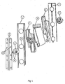
- Fig. 1 provides an illustration of a typical louver system with adjustable blades, which is limited to a pair of U-shaped members 1, a blades 2 with respective blade-holders 3, bearings 4 and two connecting rods 9.
- the blades 2 in the example illustrated are made out of extruded aluminum but that does not have to be the case. They could be made out of a plastics material, wood, glass or any other rigid material.
Landscapes
- Engineering & Computer Science (AREA)
- General Engineering & Computer Science (AREA)
- Structural Engineering (AREA)
- Chemical & Material Sciences (AREA)
- Combustion & Propulsion (AREA)
- Mechanical Engineering (AREA)
- Civil Engineering (AREA)
- Specific Sealing Or Ventilating Devices For Doors And Windows (AREA)
- Blinds (AREA)
- Operating, Guiding And Securing Of Roll- Type Closing Members (AREA)
- Curtains And Furnishings For Windows Or Doors (AREA)
- Support Of The Bearing (AREA)
- Magnetic Bearings And Hydrostatic Bearings (AREA)
Abstract
Description
- The invention relates to a blade holder and bearing to be incorporated in louver systems of the type having adjustable blades, which features high strength against torque loads and ease of assembly in the manufacturing process.
- Systems of the type, having adjustable blades, which can be angled at will, are very popular in regulating wind flow and sun block in buildings. The most common embodiment of such a system is one that consists essentially of two adjacent upright metal U shaped members, which hold plastic or metal swivel blade-holders in which the blades are inserted to form a single assembly. The blade-holders are free to rotate on their own horizontal axis when located on the U-shaped member. The synchronized movement of all the blade-holders is powered via two connecting rods that move vertically. The blade-holders are supported on the U-shaped member via bearings that clip onto the blade-holders and in doing so leave the U-shaped member locked in the middle. Note that the connecting rods are loosely riveted on the bearings so as to allow the relative movement of the one against the other. As a result the vertical movement of the connecting rods is translated into rotational motion on the bearing. Since each bearing is joined with a corresponding blade-holder and the latter holds the blade axial rotation of the blades is achieved. The vertical movement of the bars, which results in the rotation of the blades, is usually achieved via a worm gear system or via a linkage mechanism that is connected to a handle. An illustration of such a system is found in Fig 1.
- Systems of the type described above suffer from two technical drawbacks. Both of these problems relate to the high dependence of the system on the blade-holder and bearing assembly.
- The first drawback relates to the relatively low value of the maximum torque characteristics of the system. Since the movement of the blades originates from the vertical movement of the connecting rods, which in turn drive, the bearing, which is jointed on the blade-holder, this means that to a large extent the torque characteristics of the system are limited by the strength of the blade-holder and bearing joint. In the current state of the art, the blade-holder and bearing joint is achieved via a male polygon member being inserted inside a female polygon socket and a clip mechanism that stops them from sliding against each other after the insertion has occurred. In some blade-holder and bearing joints the male polygon member is part of the blade-holder and the female polygon socket is part of the bearing and in other joints the other way round. The cause of this drawback originates from the fact that when elevated torque is applied on the blade-holder and bearing joint the male polygon member is forced to rotate inside the female polygon socket and this results in the eventual destruction of the male or/and female polygon corners and the disengagement of the clip mechanism leading to the dismantling of the joint. When this happens the blade-holder no longer engages with the bearing and it is free to rotate on it own or even be removed from the louver system along with the blade leaving an unsecured hole. In the current state of the art, the blade-holder and bearing torque characteristics are limited by the material flexibility of the male polygon member and/or the female socket, which is inherently low since either one of them or both of them are made of a synthetic material which needs to posses good flexibility characteristics so as to serve other design purposes such as the clip mechanism and blade holding.
- Being able to create a high torque blade-holder and bearing joint is very important for many reasons. For example it improves the louver system in terms of security against potential burglars by increasing the amount of leverage power required to disengage a blade-holder from the bearing while the connecting rods are secured on a fixed position and thus remove a blade from the louver mechanism.
- In addition since the rotational motion of the blade-holder is transmitted via the bearing, having a high torque joint between them ensures many years of trouble free operation. This is very important in cases where the blades are improperly cut, which can place excessive torque loadings on the joint to achieve rotation.
- Having a high torque joint is also very important in achieving the tight closing of the blades against water, air and dust. Since the blades are equipped with rubber seals, at the end of their rotational cycle an increased amount of torque is required to achieve the pressing of the seals so that the blades reach the end of their rotational cycle.
- Being able to have a high torque blade-holder and bearing joint is also very important in cases where the louver system is powered via an electric motor. Although some motorized systems incorporate mechanical limit switches the majority of motorized systems use electrical limit switches. For the electrical limit switch to activate there should be a sharp rise in electrical current, which takes place when the motor torque rises. The required rise in torque occurs when the blade-holder reaches the end of its rotation and applies a break on the motor. Since the motor is still applying rotational power, prior to the activation of the electrical limit switch, an opposite reaction to this power comes from the blade-holder and bearing joint. If this is not a high strength joint then the operational life of the system is greatly reduced.
- The second drawback originates from the fact that it is technically difficult to assemble the bearing with the blade-holder. This is because prior to the assembly the bearing and the blade-holder have to be properly aligned on top of each other. In the current state of the art this is technically difficult to achieve without the requirement of special purpose assembly machines due to the inherent design of the clip mechanism that gets in the way and does not allow the ease of orientation of the blade-holder on the bearing prior to the insertion to form the joint.
- Since louver systems are required in numerous sizes depending on the window size it is very difficult and costly to keep adequate stocks on an international basis to serve each local market. For this to be carried out economically and efficiently the assembly of the mechanisms must be performed locally to each market. However this requires the setup of special assembly machines at each site, which is technically difficult to maintain.
- The object of this invention described herein is that of eliminating the drawbacks outlined. The stated object is realized with a blade-holder and bearing as described in the following specification and as characterized in the appended claims that fits common types of louver systems as described earlier and allows a high torque joint of the blade-holder on the bearing which is easy to assemble without the need of special machines or time consuming manual operations. The key to this invention is the simplicity in terms of design, construction and assembly that results in lowering the cost of investment and production.
- Accordingly, this invention provides a blade-holder consisting of a blade socket on the one side and on the other side a central male polygon member with chamfered tip equipped with guiding grooves leading to ramps followed by two openings that reveal catches, surrounded by a female polygonal socket.
- In addition it provides a bearing characterized by a circular plate consisting on the one side two projecting pins and on the other side a central female polygon socket surrounded by a male polygon member part of which consists of two projecting flexible legs equipped with hooks.
- Preferably the blade-holder and the bearing are made out of a plastics material but the blade-holder may instead be made from a rigid material such as metal.
- A preferred embodiment of the invention will now be described by way of example, with reference to the accompanying drawings, in which:
- Fig. 1 is an exploded view of the essential parts of a louver system with adjustable blades of the type that this invention applies to;
- Fig. 2 is the top and bottom views of the blade-holder;
- Fig. 3 is the top and bottom views of the bearing;
- Fig. 4 shows a section of the blade-holder and bearing assembly according to the invention, viewed from the side and in isolation from the fixture with emphasis on the creation of the high torque joint;
- Fig. 5 shows a section of the blade-holder and bearing assembly according to the invention, viewed from the side and in isolation from the fixture with emphasis on the clip mechanism; and
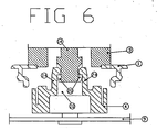
- Fig. 6 shows a section of a blade-holder and bearing according to the invention, viewed from the side and in isolation from the fixture prior to the assembly in full orientation against each other.
- Fig. 1 provides an illustration of a typical louver system with adjustable blades, which is limited to a pair of
U-shaped members 1, ablades 2 with respective blade-holders 3,bearings 4 and two connectingrods 9. - Along the length of each
U-shaped member 1 there are a series ofholes 5 at constant intervals that are used for holding the blade-holder 3 and bearing 4 assembly which in turn is used to hold theblade 2. So in effect when placing a set ofU-shaped members 1 facing each other with the blade-holder 3 and bearing 1 assemblies completed, theblades 2 can be located in the blade-holders 3 thus creating an adjustable louver system. - The
blades 2 in the example illustrated are made out of extruded aluminum but that does not have to be the case. They could be made out of a plastics material, wood, glass or any other rigid material. - The top part of the blade-
holder 3 consists of ablade socket 28 which is similarly shaped as theblades 2 to allow a tight fit, which can be secured via a clip mechanism. - On the rear side of each bearing 4 two
pins 8 are projecting which are used for engaging the connectingrods 9 and are locked via ariveting operation 10. - When the blade-
holder 3 is assembled with the bearing 4 a collar is formed 11 that is marginally less than thehole 5 in theU-shaped member 1 thus allowing the blade-holder and bearing assembly to freely rotate in respect with theU-shaped member 1. This rotation is generated via the linear movement of the connectingrods 9. The linear movement of the connectingrods 9 can be generated via a worm gear mechanism or a linkage mechanism connected to a lever. - Figure 2 shows top and bottom views of a blade-holder according to the invention. It is important to note that this blade-holder consists of a
central male component 14, a perimeterfemale socket 13 and a set ofalignment guides 20 leading to a set ofopenings 21 that reveal a set of inclined clip seats. Note that in this illustration the male components and female sockets are in a quadrangular configuration but this innovation is not restricted to only this type of polygon. - Figure 3 shows top and bottom views of a
bearing 4 according to the invention. It is important to note that the illustrated bearing is essentially a circular plate consisting on the one side two projectingpins 8 and on the other side a centralfemale polygon socket 22 surrounded by amale polygon member 23 part of which consists of two projectingflexible legs 24 equipped withhooks 26. - Figure 4 shows a section of the
bearing 4 and a section of the lower part of the blade-holder 3 in an assembly configuration on aU-shaped member 1 forming a high strength joint. It is important to note that thebearing 4male polygon element 23 engages in the blade-holder 3female polygon socket 13 and also thebearing 4female polygon socket 22 engages in the blade-holder 3male polygon element 14, thus forming a high torque joint. This type of joint can withstand much greater torques than current state of the art blade-holder and bearing joints. In current state of the art joints the blade-holder 3 and thebearing 4 have either a male or a female component. They do not have both. Current state of the art joints subjected under high torque fail to sustain the load because the male component forces the female socket to expand, by virtue of the flexibility of the material and socket design this is easy to do, and thus allow the male component to rotate within the female socket resulting to the destruction of both the male and female polygon corners leading to the disengagement of the joint. However in the case of a high torque joint, as shown in figure 4, in order for themale polygon component 14 to rotate inside thefemale socket 22 the bearingmale component 23 must be compressed against the blade-holder 3female socket 13 to allow this rotation. In effect the amount of torque that the blade-holder and bearing joint can withstand is not actually dependant on the construction of the socket but on the bearing material compression characteristics, which are typically much higher that any socket design can offer. - Figure 5 shows another section view of the
bearing 4 and section view of the lower part of the blade-holder 3 in an assembled configuration onU-shaped frame 1 forming a high strength joint with emphasis on the clip mechanism. When sliding thebearing 4 inside the blade-holder 3 the twolegs 24 bend outward to allow the blade-holder 3central section 14 to locate itself below thelegs 24. Each leg is equipped with a lip 25 which part of it forms acatch 26 that will anchor on the blade-holder 3central section part 27 in case an attempt is made to disengage the blade-holder 3 from thebearing 4 or slide the one against the other. - Current state of the art blade-holder and bearing designs are equipped with flat lips that do not have the ability to anchor themselves when pulled out, resulting in low pulling power requirements to take them apart.
- Figure 6 shows the way in which the
bearing 4 is freely aligned against the blade-holder 3 prior to the application of pressure to achieve the insertion of the one into the other. As shown in figure 6 thelegs 24 slide along guides 20 provided by the blade-holder 3 with adequate clearance to allow free movement and self alignment. Having moved a certain distance the blade-holder 3 reaches a point where itsmale component 14 forms a tight fit with the bearingsocket 22 and as a result requires additional pressure to move forward. At this point thebearing 4 sits aligned with respect to the blade-holder 3 and is ready to be inserted either by hand or via an automatic pressure device.
Claims (5)
- A blade holder and bearing assembly, for use in a louver system, the blade-holder (3) comprising a blade socket (28) on one side and on the opposing side a male component (14) and a female socket (13), one inside the other, and a set of alignment guides (20) leading to a set of holes (21) that reveal a set of inclined clip seats (27), to engage, in use, with a louver blade; and
the bearing (4) comprising a circular plate consisting on one side of two projecting pins (8) and on the other side a female socket (22) and a male member (23) part of which consists of two projecting flexible legs (24) equipped with hooks (26), the female sockets and male members of the blade holder and bearing being positioned and arranged to engage with one another in use. - A blade-holder and bearing assembly as claimed in claim 1, further comprising with a self alignment mechanism that allows the ease of assembly of the blade-holder (3) with the bearing (4).
- A blade-holder and bearing assembly as claimed in claim 1 or 2 provided with a retaining mechanism that does not allow the disengagement or lateral movement of the bearing (4) with respect to the blade-holder (3) once they have been assembled together.
- A blade holder and bearing assembly according to any preceding claim, wherein the bearing is made from a plastics or synthetic material, provide sufficient flexibility to the legs (24) to allow proper engagement with the blade-holder (3).
- A blade-holder and bearing assembly according to any preceding claim, wherein the blade-holder is made from a plastics or rigid material to allow proper engagement with the bearing (3).
Priority Applications (1)
| Application Number | Priority Date | Filing Date | Title |
|---|---|---|---|
| CY20081100550T CY1107970T1 (en) | 2005-01-07 | 2008-05-26 | WING SUPPORT AND BEARING FOR ADJUSTABLE MOBILE PARTS SYSTEM CONTAINING HIGH TORQUE FEATURES |
Applications Claiming Priority (1)
| Application Number | Priority Date | Filing Date | Title |
|---|---|---|---|
| CY0500002A CY2518B1 (en) | 2005-01-07 | 2005-01-07 |
Publications (2)
| Publication Number | Publication Date |
|---|---|
| EP1679477A1 true EP1679477A1 (en) | 2006-07-12 |
| EP1679477B1 EP1679477B1 (en) | 2008-04-30 |
Family
ID=38729081
Family Applications (1)
| Application Number | Title | Priority Date | Filing Date |
|---|---|---|---|
| EP05257153A Active EP1679477B1 (en) | 2005-01-07 | 2005-11-21 | Blade-holder & bearing for an adjustable louvre system featuring high torque characteristics |
Country Status (6)
| Country | Link |
|---|---|
| EP (1) | EP1679477B1 (en) |
| AT (1) | ATE393902T1 (en) |
| CY (2) | CY2518B1 (en) |
| DE (1) | DE602005006373D1 (en) |
| ES (1) | ES2303200T3 (en) |
| PT (1) | PT1679477E (en) |
Cited By (4)
| Publication number | Priority date | Publication date | Assignee | Title |
|---|---|---|---|---|
| ITBO20110491A1 (en) * | 2011-08-05 | 2013-02-06 | Nuova Eurosystem S R L | ASSEMBLY FOR THE FITTING OF LATCHED FRAMES TO THE FRAME OF A DOOR OF A SHUTTER |
| US20170314324A1 (en) * | 2016-04-29 | 2017-11-02 | I.Quattro S.R.L. | Actuation device for the slats of a shutter |
| CN108131086A (en) * | 2018-01-22 | 2018-06-08 | 陈映君 | A kind of blinds folder of shutter |
| EP3311885A4 (en) * | 2015-06-18 | 2019-06-05 | Midoenc Co., Ltd. | Damper switch |
Citations (5)
| Publication number | Priority date | Publication date | Assignee | Title |
|---|---|---|---|---|
| GB1042731A (en) * | 1961-12-05 | 1966-09-14 | Beta Aluminium Products Ltd | Adjustable louvre windows or shutters |
| US4643081A (en) * | 1985-05-06 | 1987-02-17 | Pillar Naco Industries (Europe) Srl | Louver system with adjustable slats, featuring removable modular slat clips |
| EP0432828A1 (en) * | 1989-12-12 | 1991-06-19 | Royal-Pat S.R.L. | Assembly of an end support and an operating crank for rotatable slats or blades of shutters |
| GB2285123A (en) * | 1993-10-14 | 1995-06-28 | Interlock Ind Ltd | Louvre windows;sealing louvre mounts upon closure |
| US5794380A (en) * | 1997-01-24 | 1998-08-18 | Reflectolite Products Company, Inc. | Louvre window clip assembly |
-
2005
- 2005-01-07 CY CY0500002A patent/CY2518B1/xx unknown
- 2005-11-21 EP EP05257153A patent/EP1679477B1/en active Active
- 2005-11-21 ES ES05257153T patent/ES2303200T3/en active Active
- 2005-11-21 PT PT05257153T patent/PT1679477E/en unknown
- 2005-11-21 DE DE602005006373T patent/DE602005006373D1/en active Active
- 2005-11-21 AT AT05257153T patent/ATE393902T1/en not_active IP Right Cessation
-
2008
- 2008-05-26 CY CY20081100550T patent/CY1107970T1/en unknown
Patent Citations (5)
| Publication number | Priority date | Publication date | Assignee | Title |
|---|---|---|---|---|
| GB1042731A (en) * | 1961-12-05 | 1966-09-14 | Beta Aluminium Products Ltd | Adjustable louvre windows or shutters |
| US4643081A (en) * | 1985-05-06 | 1987-02-17 | Pillar Naco Industries (Europe) Srl | Louver system with adjustable slats, featuring removable modular slat clips |
| EP0432828A1 (en) * | 1989-12-12 | 1991-06-19 | Royal-Pat S.R.L. | Assembly of an end support and an operating crank for rotatable slats or blades of shutters |
| GB2285123A (en) * | 1993-10-14 | 1995-06-28 | Interlock Ind Ltd | Louvre windows;sealing louvre mounts upon closure |
| US5794380A (en) * | 1997-01-24 | 1998-08-18 | Reflectolite Products Company, Inc. | Louvre window clip assembly |
Cited By (6)
| Publication number | Priority date | Publication date | Assignee | Title |
|---|---|---|---|---|
| ITBO20110491A1 (en) * | 2011-08-05 | 2013-02-06 | Nuova Eurosystem S R L | ASSEMBLY FOR THE FITTING OF LATCHED FRAMES TO THE FRAME OF A DOOR OF A SHUTTER |
| EP3311885A4 (en) * | 2015-06-18 | 2019-06-05 | Midoenc Co., Ltd. | Damper switch |
| US10670291B2 (en) | 2015-06-18 | 2020-06-02 | Midoenc Co., Ltd. | Damper switch |
| US20170314324A1 (en) * | 2016-04-29 | 2017-11-02 | I.Quattro S.R.L. | Actuation device for the slats of a shutter |
| CN108131086A (en) * | 2018-01-22 | 2018-06-08 | 陈映君 | A kind of blinds folder of shutter |
| CN108131086B (en) * | 2018-01-22 | 2023-11-24 | 清远市首一建筑新材料有限公司 | Shutter clip of shutter |
Also Published As
| Publication number | Publication date |
|---|---|
| CY1107970T1 (en) | 2013-09-04 |
| CY2518B1 (en) | 2006-02-08 |
| ATE393902T1 (en) | 2008-05-15 |
| ES2303200T3 (en) | 2008-08-01 |
| PT1679477E (en) | 2008-06-06 |
| EP1679477B1 (en) | 2008-04-30 |
| DE602005006373D1 (en) | 2008-06-12 |
Similar Documents
| Publication | Publication Date | Title |
|---|---|---|
| EP1679477B1 (en) | Blade-holder & bearing for an adjustable louvre system featuring high torque characteristics | |
| JP4005148B2 (en) | Support means for shielding device | |
| CA2879474C (en) | Panel fastener | |
| KR20090087634A (en) | A shutter switchgear for ventilator window | |
| CN115371171A (en) | Ventilator with self-cleaning function | |
| KR102087666B1 (en) | Louver system with detachable wings | |
| EP3009728A1 (en) | Retaining element for stand device and correspondingly formed components | |
| CN115263168B (en) | Shutter dimmer | |
| CN214223271U (en) | Air conditioner plate for placing outdoor unit of air conditioner | |
| CN214007620U (en) | Fan fixing device and range hood with same | |
| CN218715355U (en) | Exempt from interior suspension type that punches and face limit protection frame | |
| KR200316929Y1 (en) | a window ventilation shutter for circuit breaker | |
| KR102628883B1 (en) | Automatic switchgear for louver | |
| CN218030968U (en) | Telescopic positioning device | |
| WO2021251353A1 (en) | Hinge and door mechanism | |
| US224908A (en) | Andrew l | |
| CN212353778U (en) | Manual tarpaulin rolling device for open vehicle | |
| US20090272501A1 (en) | Tensioning pin for shutter systems | |
| CN220017670U (en) | Window type air conditioner | |
| JP6424567B2 (en) | Pull-type fittings, and door cars with built-in adjustment function | |
| CN219492786U (en) | Screw fastener capable of preventing nut from loosening | |
| CN216110476U (en) | Fast-assembling side shutter partition mechanism for awning | |
| CN218177068U (en) | Connecting assembly of aluminum alloy door and window frame | |
| CN217999256U (en) | Strip lock | |
| CN219166330U (en) | Angle-adjustable cleaning tool |
Legal Events
| Date | Code | Title | Description |
|---|---|---|---|
| PUAI | Public reference made under article 153(3) epc to a published international application that has entered the european phase |
Free format text: ORIGINAL CODE: 0009012 |
|
| AK | Designated contracting states |
Kind code of ref document: A1 Designated state(s): AT BE BG CH CY CZ DE DK EE ES FI FR GB GR HU IE IS IT LI LT LU LV MC NL PL PT RO SE SI SK TR |
|
| AX | Request for extension of the european patent |
Extension state: AL BA HR MK YU |
|
| 17P | Request for examination filed |
Effective date: 20070102 |
|
| AKX | Designation fees paid |
Designated state(s): AT BE BG CH CY CZ DE DK EE ES FI FR GB GR HU IE IS IT LI LT LU LV MC NL PL PT RO SE SI SK TR |
|
| GRAP | Despatch of communication of intention to grant a patent |
Free format text: ORIGINAL CODE: EPIDOSNIGR1 |
|
| GRAS | Grant fee paid |
Free format text: ORIGINAL CODE: EPIDOSNIGR3 |
|
| GRAA | (expected) grant |
Free format text: ORIGINAL CODE: 0009210 |
|
| AK | Designated contracting states |
Kind code of ref document: B1 Designated state(s): AT BE BG CH CY CZ DE DK EE ES FI FR GB GR HU IE IS IT LI LT LU LV MC NL PL PT RO SE SI SK TR |
|
| REG | Reference to a national code |
Ref country code: GB Ref legal event code: FG4D |
|
| REG | Reference to a national code |
Ref country code: CH Ref legal event code: EP |
|
| REG | Reference to a national code |
Ref country code: PT Ref legal event code: SC4A Free format text: AVAILABILITY OF NATIONAL TRANSLATION Effective date: 20080527 |
|
| REG | Reference to a national code |
Ref country code: IE Ref legal event code: FG4D Free format text: LANGUAGE OF EP DOCUMENT: FRENCH |
|
| REF | Corresponds to: |
Ref document number: 602005006373 Country of ref document: DE Date of ref document: 20080612 Kind code of ref document: P |
|
| REG | Reference to a national code |
Ref country code: RO Ref legal event code: EPE |
|
| REG | Reference to a national code |
Ref country code: GR Ref legal event code: EP Ref document number: 20080401561 Country of ref document: GR |
|
| REG | Reference to a national code |
Ref country code: CH Ref legal event code: PK Free format text: DAS PRIORITAETSAKTENZEICHEN WURDE BERICHTIGT: |
|
| REG | Reference to a national code |
Ref country code: ES Ref legal event code: FG2A Ref document number: 2303200 Country of ref document: ES Kind code of ref document: T3 |
|
| PG25 | Lapsed in a contracting state [announced via postgrant information from national office to epo] |
Ref country code: SI Free format text: LAPSE BECAUSE OF FAILURE TO SUBMIT A TRANSLATION OF THE DESCRIPTION OR TO PAY THE FEE WITHIN THE PRESCRIBED TIME-LIMIT Effective date: 20080430 |
|
| NLV1 | Nl: lapsed or annulled due to failure to fulfill the requirements of art. 29p and 29m of the patents act | ||
| PG25 | Lapsed in a contracting state [announced via postgrant information from national office to epo] |
Ref country code: FI Free format text: LAPSE BECAUSE OF FAILURE TO SUBMIT A TRANSLATION OF THE DESCRIPTION OR TO PAY THE FEE WITHIN THE PRESCRIBED TIME-LIMIT Effective date: 20080430 Ref country code: NL Free format text: LAPSE BECAUSE OF FAILURE TO SUBMIT A TRANSLATION OF THE DESCRIPTION OR TO PAY THE FEE WITHIN THE PRESCRIBED TIME-LIMIT Effective date: 20080430 |
|
| PG25 | Lapsed in a contracting state [announced via postgrant information from national office to epo] |
Ref country code: AT Free format text: LAPSE BECAUSE OF FAILURE TO SUBMIT A TRANSLATION OF THE DESCRIPTION OR TO PAY THE FEE WITHIN THE PRESCRIBED TIME-LIMIT Effective date: 20080430 Ref country code: PL Free format text: LAPSE BECAUSE OF FAILURE TO SUBMIT A TRANSLATION OF THE DESCRIPTION OR TO PAY THE FEE WITHIN THE PRESCRIBED TIME-LIMIT Effective date: 20080430 Ref country code: LV Free format text: LAPSE BECAUSE OF FAILURE TO SUBMIT A TRANSLATION OF THE DESCRIPTION OR TO PAY THE FEE WITHIN THE PRESCRIBED TIME-LIMIT Effective date: 20080430 |
|
| PG25 | Lapsed in a contracting state [announced via postgrant information from national office to epo] |
Ref country code: IS Free format text: LAPSE BECAUSE OF FAILURE TO SUBMIT A TRANSLATION OF THE DESCRIPTION OR TO PAY THE FEE WITHIN THE PRESCRIBED TIME-LIMIT Effective date: 20080830 |
|
| PG25 | Lapsed in a contracting state [announced via postgrant information from national office to epo] |
Ref country code: SE Free format text: LAPSE BECAUSE OF FAILURE TO SUBMIT A TRANSLATION OF THE DESCRIPTION OR TO PAY THE FEE WITHIN THE PRESCRIBED TIME-LIMIT Effective date: 20080731 Ref country code: DK Free format text: LAPSE BECAUSE OF FAILURE TO SUBMIT A TRANSLATION OF THE DESCRIPTION OR TO PAY THE FEE WITHIN THE PRESCRIBED TIME-LIMIT Effective date: 20080430 Ref country code: CZ Free format text: LAPSE BECAUSE OF FAILURE TO SUBMIT A TRANSLATION OF THE DESCRIPTION OR TO PAY THE FEE WITHIN THE PRESCRIBED TIME-LIMIT Effective date: 20080430 Ref country code: LT Free format text: LAPSE BECAUSE OF FAILURE TO SUBMIT A TRANSLATION OF THE DESCRIPTION OR TO PAY THE FEE WITHIN THE PRESCRIBED TIME-LIMIT Effective date: 20080430 |
|
| EN | Fr: translation not filed | ||
| PG25 | Lapsed in a contracting state [announced via postgrant information from national office to epo] |
Ref country code: SK Free format text: LAPSE BECAUSE OF FAILURE TO SUBMIT A TRANSLATION OF THE DESCRIPTION OR TO PAY THE FEE WITHIN THE PRESCRIBED TIME-LIMIT Effective date: 20080430 Ref country code: BE Free format text: LAPSE BECAUSE OF FAILURE TO SUBMIT A TRANSLATION OF THE DESCRIPTION OR TO PAY THE FEE WITHIN THE PRESCRIBED TIME-LIMIT Effective date: 20080430 |
|
| PGFP | Annual fee paid to national office [announced via postgrant information from national office to epo] |
Ref country code: ES Payment date: 20081216 Year of fee payment: 4 Ref country code: PT Payment date: 20081031 Year of fee payment: 4 Ref country code: RO Payment date: 20081001 Year of fee payment: 4 |
|
| PLBE | No opposition filed within time limit |
Free format text: ORIGINAL CODE: 0009261 |
|
| STAA | Information on the status of an ep patent application or granted ep patent |
Free format text: STATUS: NO OPPOSITION FILED WITHIN TIME LIMIT |
|
| PGFP | Annual fee paid to national office [announced via postgrant information from national office to epo] |
Ref country code: BG Payment date: 20081112 Year of fee payment: 4 |
|
| 26N | No opposition filed |
Effective date: 20090202 |
|
| PG25 | Lapsed in a contracting state [announced via postgrant information from national office to epo] |
Ref country code: FR Free format text: LAPSE BECAUSE OF FAILURE TO SUBMIT A TRANSLATION OF THE DESCRIPTION OR TO PAY THE FEE WITHIN THE PRESCRIBED TIME-LIMIT Effective date: 20090227 Ref country code: DE Free format text: LAPSE BECAUSE OF FAILURE TO SUBMIT A TRANSLATION OF THE DESCRIPTION OR TO PAY THE FEE WITHIN THE PRESCRIBED TIME-LIMIT Effective date: 20080731 Ref country code: EE Free format text: LAPSE BECAUSE OF FAILURE TO SUBMIT A TRANSLATION OF THE DESCRIPTION OR TO PAY THE FEE WITHIN THE PRESCRIBED TIME-LIMIT Effective date: 20080430 |
|
| PG25 | Lapsed in a contracting state [announced via postgrant information from national office to epo] |
Ref country code: MC Free format text: LAPSE BECAUSE OF NON-PAYMENT OF DUE FEES Effective date: 20081130 |
|
| REG | Reference to a national code |
Ref country code: IE Ref legal event code: MM4A |
|
| PG25 | Lapsed in a contracting state [announced via postgrant information from national office to epo] |
Ref country code: IE Free format text: LAPSE BECAUSE OF NON-PAYMENT OF DUE FEES Effective date: 20081121 |
|
| REG | Reference to a national code |
Ref country code: PT Ref legal event code: MM4A Free format text: LAPSE DUE TO NON-PAYMENT OF FEES Effective date: 20100521 |
|
| REG | Reference to a national code |
Ref country code: CH Ref legal event code: PL |
|
| GBPC | Gb: european patent ceased through non-payment of renewal fee |
Effective date: 20091121 |
|
| PG25 | Lapsed in a contracting state [announced via postgrant information from national office to epo] |
Ref country code: BG Free format text: LAPSE BECAUSE OF EXPIRATION OF PROTECTION Effective date: 20100531 Ref country code: LU Free format text: LAPSE BECAUSE OF NON-PAYMENT OF DUE FEES Effective date: 20081121 Ref country code: PT Free format text: LAPSE BECAUSE OF NON-PAYMENT OF DUE FEES Effective date: 20100521 Ref country code: HU Free format text: LAPSE BECAUSE OF FAILURE TO SUBMIT A TRANSLATION OF THE DESCRIPTION OR TO PAY THE FEE WITHIN THE PRESCRIBED TIME-LIMIT Effective date: 20081101 |
|
| PG25 | Lapsed in a contracting state [announced via postgrant information from national office to epo] |
Ref country code: TR Free format text: LAPSE BECAUSE OF FAILURE TO SUBMIT A TRANSLATION OF THE DESCRIPTION OR TO PAY THE FEE WITHIN THE PRESCRIBED TIME-LIMIT Effective date: 20080430 |
|
| PG25 | Lapsed in a contracting state [announced via postgrant information from national office to epo] |
Ref country code: CH Free format text: LAPSE BECAUSE OF NON-PAYMENT OF DUE FEES Effective date: 20091130 Ref country code: LI Free format text: LAPSE BECAUSE OF NON-PAYMENT OF DUE FEES Effective date: 20091130 |
|
| PG25 | Lapsed in a contracting state [announced via postgrant information from national office to epo] |
Ref country code: GB Free format text: LAPSE BECAUSE OF NON-PAYMENT OF DUE FEES Effective date: 20091121 |
|
| PG25 | Lapsed in a contracting state [announced via postgrant information from national office to epo] |
Ref country code: RO Free format text: LAPSE BECAUSE OF NON-PAYMENT OF DUE FEES Effective date: 20091121 |
|
| REG | Reference to a national code |
Ref country code: ES Ref legal event code: FD2A Effective date: 20110309 |
|
| PG25 | Lapsed in a contracting state [announced via postgrant information from national office to epo] |
Ref country code: ES Free format text: LAPSE BECAUSE OF NON-PAYMENT OF DUE FEES Effective date: 20110308 |
|
| PG25 | Lapsed in a contracting state [announced via postgrant information from national office to epo] |
Ref country code: ES Free format text: LAPSE BECAUSE OF NON-PAYMENT OF DUE FEES Effective date: 20091122 |
|
| PGFP | Annual fee paid to national office [announced via postgrant information from national office to epo] |
Ref country code: IT Payment date: 20081130 Year of fee payment: 4 |
|
| PGFP | Annual fee paid to national office [announced via postgrant information from national office to epo] |
Ref country code: CY Payment date: 20121015 Year of fee payment: 8 |
|
| PGFP | Annual fee paid to national office [announced via postgrant information from national office to epo] |
Ref country code: GR Payment date: 20121016 Year of fee payment: 8 |
|
| REG | Reference to a national code |
Ref country code: GR Ref legal event code: ML Ref document number: 20080401561 Country of ref document: GR Effective date: 20140603 |
|
| PG25 | Lapsed in a contracting state [announced via postgrant information from national office to epo] |
Ref country code: GR Free format text: LAPSE BECAUSE OF NON-PAYMENT OF DUE FEES Effective date: 20140603 Ref country code: CY Free format text: LAPSE BECAUSE OF NON-PAYMENT OF DUE FEES Effective date: 20131121 |