CN219166330U - A cleaning tool with adjustable angle - Google Patents
A cleaning tool with adjustable angle Download PDFInfo
- Publication number
- CN219166330U CN219166330U CN202222883978.XU CN202222883978U CN219166330U CN 219166330 U CN219166330 U CN 219166330U CN 202222883978 U CN202222883978 U CN 202222883978U CN 219166330 U CN219166330 U CN 219166330U
- Authority
- CN
- China
- Prior art keywords
- hole
- worm
- rod
- transmission column
- installation
- Prior art date
- Legal status (The legal status is an assumption and is not a legal conclusion. Google has not performed a legal analysis and makes no representation as to the accuracy of the status listed.)
- Active
Links
Images


Classifications
-
- Y—GENERAL TAGGING OF NEW TECHNOLOGICAL DEVELOPMENTS; GENERAL TAGGING OF CROSS-SECTIONAL TECHNOLOGIES SPANNING OVER SEVERAL SECTIONS OF THE IPC; TECHNICAL SUBJECTS COVERED BY FORMER USPC CROSS-REFERENCE ART COLLECTIONS [XRACs] AND DIGESTS
- Y02—TECHNOLOGIES OR APPLICATIONS FOR MITIGATION OR ADAPTATION AGAINST CLIMATE CHANGE
- Y02E—REDUCTION OF GREENHOUSE GAS [GHG] EMISSIONS, RELATED TO ENERGY GENERATION, TRANSMISSION OR DISTRIBUTION
- Y02E10/00—Energy generation through renewable energy sources
- Y02E10/50—Photovoltaic [PV] energy
Landscapes
- Cleaning Implements For Floors, Carpets, Furniture, Walls, And The Like (AREA)
Abstract
本实用新型公开了一种角度可调节的清洁工具,包括操作杆和设置于所述操作杆一端的清洁头,还包括蜗杆件和传动柱,所述操作杆用于安装所述清洁头的一端设置有安装部,所述蜗杆件转动设置于所述安装部上,所述传动柱也转动设置于所述安装部上,所述传动柱的轴线与所述蜗杆件的轴线相垂直;所述传动柱的周向外壁至少部分设置有与所述蜗杆件相啮合的传动齿,所述传动柱通过所述传动齿与所述蜗杆件传动连接;所述传动柱的周向外壁与所述清洁头相连接。本实用新型中,可以旋转所述蜗杆件,以实现无级调节并控制所述清洁头旋转角度的目的,且不用设置额外的锁定机构进行锁定,结构简单,使用方便。
The utility model discloses an angle-adjustable cleaning tool, which comprises an operating rod and a cleaning head arranged at one end of the operating rod, and also includes a worm part and a transmission column, and the operating rod is used for installing one end of the cleaning head. A mounting part is provided, the worm part is rotatably arranged on the mounting part, the transmission column is also rotatably provided on the installation part, and the axis of the transmission column is perpendicular to the axis of the worm part; the The peripheral outer wall of the transmission column is at least partly provided with transmission teeth meshed with the worm member, and the transmission column is in transmission connection with the worm member through the transmission teeth; the peripheral outer wall of the transmission column is connected to the cleaning head connected. In the utility model, the worm member can be rotated to achieve the purpose of stepless adjustment and control of the rotation angle of the cleaning head, and no additional locking mechanism is required for locking. The structure is simple and easy to use.
Description
技术领域technical field
本实用新型涉及清洁工具技术领域,尤其是一种角度可调节的清洁工具。The utility model relates to the technical field of cleaning tools, in particular to a cleaning tool with an adjustable angle.
背景技术Background technique
室内的家具、电器、灯具放置时间长了会在外表面沉积灰尘,这些灰尘不宜用湿布去除,一般采用除尘掸去除这些灰尘。目前市场上使用的除尘掸一般只有一个角度,在使用的过程中家具、电器或灯具外表面的很多部位不易清洁到,导致灰尘不能完全清除。Indoor furniture, electrical appliances, and lamps will accumulate dust on the outer surface if they are placed for a long time. This dust should not be removed with a damp cloth. Generally, a duster is used to remove the dust. At present, the dust collectors used in the market generally have only one angle, and many parts of the outer surfaces of furniture, electrical appliances or lamps are not easy to clean during use, resulting in incomplete removal of dust.
现有市场上出现一种可调角度的除尘掸手柄,但是其中需要锁定机构对调节角度后的清洁头进行锁定固定,结构较为复杂,从而导致清洁工具产品的成本较高;另外,其锁定机构的稳定性较差,导致清洁头无法很好地保持固定状态,且无法做到按需调节的作用,使用具有一定的局限性。There is an angle-adjustable duster handle in the market, but a locking mechanism is required to lock and fix the cleaning head after the angle is adjusted, and the structure is relatively complicated, which leads to high cost of cleaning tool products; in addition, the locking mechanism The stability of the cleaning head is poor, so that the cleaning head cannot be kept in a fixed state, and it cannot be adjusted on demand, so the use has certain limitations.
实用新型内容Utility model content
为了克服现有技术中存在的不足,本实用新型提供了一种角度可调节的清洁工具,其通过蜗杆件与传动柱配合,实现无级调节所述清洁头角度的目的,且通过蜗杆件与传动柱的自锁传动配合,使得其无需设置额外的锁定机构进行锁定,结构简单,使用方便。In order to overcome the deficiencies in the prior art, the utility model provides an angle-adjustable cleaning tool, which realizes the purpose of steplessly adjusting the angle of the cleaning head through the cooperation of the worm part and the transmission column, and through the worm part and the The self-locking transmission of the transmission column makes it unnecessary to set up an additional locking mechanism for locking, and the structure is simple and easy to use.
为了达到上述目的,本实用新型采用如下技术方案来实现的:In order to achieve the above object, the utility model adopts the following technical solutions to realize:
一种角度可调节的清洁工具,包括操作杆和设置于所述操作杆一端的清洁头,还包括蜗杆件和传动柱,所述操作杆用于安装所述清洁头的一端设置有安装部,所述蜗杆件转动设置于所述安装部上,所述传动柱也转动设置于所述安装部上,所述传动柱的轴线与所述蜗杆件的轴线相垂直;An angle-adjustable cleaning tool includes an operating rod and a cleaning head arranged at one end of the operating rod, and also includes a worm member and a transmission column, and the end of the operating rod for installing the cleaning head is provided with a mounting portion, The worm member is rotatably arranged on the installation part, and the transmission column is also rotatably arranged on the installation part, and the axis of the transmission column is perpendicular to the axis of the worm member;
所述传动柱的周向外壁至少部分设置有与所述蜗杆件相啮合的传动齿,所述传动柱通过所述传动齿与所述蜗杆件传动连接;所述传动柱的周向外壁与所述清洁头相连接。The peripheral outer wall of the transmission column is at least partly provided with transmission teeth meshed with the worm member, and the transmission column is in transmission connection with the worm member through the transmission teeth; the peripheral outer wall of the transmission column is connected to the worm member connected to the cleaning head.
具体地,所述操作杆有多节短杆组成,所述短杆至少设置有两个,相邻的两个短杆之间螺纹连接,用户可根据实际情况组装多节短杆以便于进行打扫;Specifically, the operating rod is composed of multi-section short rods, at least two short rods are provided, and two adjacent short rods are threaded, and the user can assemble multi-section short rods according to the actual situation to facilitate cleaning. ;
所述传动柱位于所述蜗杆件的上方;The transmission column is located above the worm member;
采用上述结构,所述传动柱通过所述传动齿和所述蜗杆件传动连接,在操作时,转动所述蜗杆件,所述蜗杆件带动所述传动柱转动,进而带动所述清洁头转动,从而实现无级调节所述清洁头角度的目的;其中,所述安装部为所述蜗杆件和所述传动柱提供安装空间,以便于将所述清洁头转动连接在所述操作杆上。With the above-mentioned structure, the transmission column is connected to the worm part through the transmission teeth. During operation, the worm part is rotated, and the worm part drives the transmission column to rotate, and then drives the cleaning head to rotate. Thereby, the purpose of steplessly adjusting the angle of the cleaning head is achieved; wherein, the installation part provides installation space for the worm member and the transmission column, so as to rotatably connect the cleaning head to the operating rod.
进一步地,所述安装部可拆卸设置于所述操作杆上。Further, the installation part is detachably arranged on the operating rod.
采用上述结构,便于用户将所述操作杆和清洁头进行拆装。With the above structure, it is convenient for the user to disassemble and assemble the operating rod and the cleaning head.
进一步地,所述蜗杆件与所述传动柱自锁传动配合,即所述蜗杆件的导程角满足条件时,所述蜗杆件能够驱动所述传动柱转动,所述传动柱无法驱动所述蜗杆件转动实现自锁。Further, the worm part is in self-locking transmission cooperation with the transmission column, that is, when the lead angle of the worm part satisfies the conditions, the worm part can drive the transmission column to rotate, and the transmission column cannot drive the The worm part rotates to realize self-locking.
采用上述结构,所以蜗杆件不会受到所述传动柱影响而转动,进而可以旋转所述蜗杆件,以实现调节并控制所述清洁头旋转角度的目的,且不用设置额外的锁定机构进行锁定,结构简单,使用方便。With the above structure, the worm member will not be rotated by the influence of the transmission column, and then the worm member can be rotated to achieve the purpose of adjusting and controlling the rotation angle of the cleaning head, and there is no need to set an additional locking mechanism for locking. The structure is simple and the use is convenient.
进一步地,所述安装部包括安装筒,所述安装筒的侧壁贯穿设置有安装孔;Further, the installation part includes an installation cylinder, and the side wall of the installation cylinder is provided with installation holes;
所述操作杆的上端设置有安装杆,所述安装杆用于插接进所述安装筒内,所述安装杆的侧壁设置有弹性按钮,所述弹性按钮用于与所述安装孔相卡接,且所述弹性按钮能在外力作用下缩进所述安装筒内部。The upper end of the operating rod is provided with a mounting rod, and the mounting rod is used for inserting into the mounting cylinder, and the side wall of the mounting rod is provided with an elastic button, and the elastic button is used for connecting with the mounting hole. clamping, and the elastic button can be retracted into the inside of the installation barrel under the action of external force.
具体地,所述安装杆的侧壁设置有凹槽,所述弹性按钮包括弹片和凸起钮,所述弹片用于将所述凸起钮连接在所述凹槽的侧壁,正常状态下的所述凸起钮凸出于所述安装杆的侧壁,当所述凸起钮受到挤压时,所述凸起钮能够缩进所述凹槽内;或者,所述弹片可以用弹簧进行代替。Specifically, the side wall of the installation rod is provided with a groove, and the elastic button includes an elastic piece and a raised button, and the elastic piece is used to connect the raised button to the side wall of the groove. The protruding button protrudes from the side wall of the installation rod, and when the protruding button is squeezed, the protruding button can be retracted into the groove; or, the elastic piece can use a spring to replace.
采用上述结构,通过按压所述凸起钮,所述凸起钮挤压所述弹簧或者弹片,使得所述凸起钮缩进所述凹槽内,此时,将所述安装部套接在所述安装杆上,并使得所述凸起钮与所述安装孔对齐,然后去除对所述凸起钮的外力,所述凸起钮受所述弹簧或者所述弹片的作用复位,而凸出于所述安装杆的侧壁且通过所述安装孔凸出于所述安装筒的外壁,进而使得所述凸起钮与所述安装孔相卡接,使得所述安装部固定在所述操作杆上;拆卸时,按压所述凸起钮,所述凸起钮挤压所述弹簧或者弹片,使得所述凸起钮缩进所述凹槽内进而缩进所述安装筒内部,此时,便于将所述安装部从所述操作杆上取下,整个安装于拆卸过程简单便捷。With the above structure, by pressing the protruding button, the protruding button presses the spring or elastic piece, so that the protruding button retracts into the groove, at this time, the mounting part is sleeved on the on the installation rod, and align the protruding button with the mounting hole, and then remove the external force on the protruding button, the protruding button is reset by the action of the spring or the elastic piece, and the protruding button Out of the side wall of the installation rod and protrudes from the outer wall of the installation cylinder through the installation hole, so that the raised button is engaged with the installation hole, so that the installation part is fixed on the On the operating rod; when dismounting, press the protruding button, and the protruding button will press the spring or shrapnel, so that the protruding button retracts into the groove and then retracts into the installation cylinder. When, it is convenient to remove the installation part from the operating rod, and the whole installation and disassembly process is simple and convenient.
进一步地,所述安装部包括相对设置的连接板和支承板,所述连接板上设置有旋转孔;所述支承板上设置有支撑孔,且所述支撑孔与所述旋转孔同轴设置;具体的,所述连接板和支承板设置在安装筒上方。Further, the installation part includes a connecting plate and a supporting plate oppositely arranged, and a rotation hole is provided on the connecting plate; a supporting hole is provided on the supporting plate, and the supporting hole is coaxially arranged with the rotating hole ; Specifically, the connecting plate and the supporting plate are arranged above the installation cylinder.
所述蜗杆件包括蜗杆本体、连接管和旋钮,所述连接管的一端与所述旋钮固定连接,所述连接管的另一端与所述蜗杆本体可拆卸连接,所述连接管用于贯穿所述旋转孔并与所述旋转孔转动连接,所述蜗杆本体远离所述连接管的尾端贯穿所述支撑孔;The worm component includes a worm body, a connecting pipe and a knob, one end of the connecting pipe is fixedly connected to the knob, the other end of the connecting pipe is detachably connected to the worm body, and the connecting pipe is used to pass through the The rotation hole is rotatably connected with the rotation hole, and the tail end of the worm body away from the connecting pipe passes through the support hole;
所述蜗杆本体的尾端在所述支撑孔的两侧分别凸起形成限位凸起。The tail ends of the worm body protrude respectively on both sides of the support hole to form limiting protrusions.
具体的,所述连接管和旋钮为一体件。Specifically, the connecting pipe and the knob are in one piece.
采用上述结构,所述旋转孔用于安装所述连接管,所述支撑孔用于安装所述蜗杆本体的尾端,以使所述蜗杆本体固定于所述安装筒的上方;所述限位凸起的设置能够限制所述蜗杆件的轴向运动,所述蜗杆件的转动更加稳定,与所述传动柱的传动更加可靠。With the above structure, the rotation hole is used to install the connecting pipe, and the support hole is used to install the tail end of the worm body, so that the worm body is fixed above the installation cylinder; The setting of the protrusion can restrict the axial movement of the worm member, the rotation of the worm member is more stable, and the transmission with the transmission column is more reliable.
具体的,所述支撑孔的半径沿着远离所述连接板方向逐渐减小,且所述支撑孔远离所述连接板的一端侧壁上设置有缺槽,使得所述支撑孔的侧壁具有弹性;所述蜗杆本体的尾端半径沿着远离所述连接板方向逐渐减小以与所述支撑孔相匹配;上述结构,便于所述蜗杆本体的尾端与支撑孔的安装配合。Specifically, the radius of the support hole gradually decreases along the direction away from the connecting plate, and a notch is provided on the side wall of the end of the supporting hole away from the connecting plate, so that the side wall of the supporting hole has Elasticity; the radius of the tail end of the worm body gradually decreases along the direction away from the connecting plate to match the support hole; the above structure facilitates the installation and cooperation of the tail end of the worm body and the support hole.
所述旋钮通过所述连接管与所述蜗杆本体相连接,所述蜗杆本体安装在所述安装部内部时,所述旋钮位于所述安装部的外壁,以便于用户从外部调节所述旋钮,以达到调节所述蜗杆本体的目的。The knob is connected to the worm body through the connecting pipe. When the worm body is installed inside the installation part, the knob is located on the outer wall of the installation part, so that the user can adjust the knob from the outside. In order to achieve the purpose of adjusting the worm body.
所述连接板和所述支承板相对设置,有利于对所述蜗杆本体进行支撑,使得所述蜗杆本体转动设置在所述安装筒上;其中,所述连接管的另一端与所述蜗杆本体可拆卸连接,便于实际生产安装。The connecting plate and the support plate are arranged opposite to each other, which is beneficial to support the worm body, so that the worm body is rotatably arranged on the installation cylinder; wherein, the other end of the connecting pipe is connected to the worm body The detachable connection is convenient for actual production installation.
进一步地,所述蜗杆本体的一端具有连接杆,所述连接杆的外壁对称设置有弹性凸起;Further, one end of the worm body has a connecting rod, and the outer wall of the connecting rod is symmetrically provided with elastic protrusions;
所述连接管的侧壁贯穿设置有凸起配合孔,所述弹性凸起用于与所述凸起配合孔相卡接。The side wall of the connecting pipe is provided with a protrusion fitting hole through, and the elastic protrusion is used to engage with the protrusion fitting hole.
具体地,所述连接杆为中空杆,以便于用户通过按压所述弹性凸起而使所述弹性凸起缩进所述连接杆中。Specifically, the connecting rod is a hollow rod, so that the user can retract the elastic protrusion into the connecting rod by pressing the elastic protrusion.
采用上述结构,在将所述蜗杆本体安装在所述连接管上时,将所述弹性凸起朝所述连接杆内部按压,使得所述弹性凸起缩进所述连接杆中,此时,将所述连接杆插接进所述连接管中,并使得所述弹性凸起与所述凸起配合孔相对齐,然后,所述弹性凸起复位进而与所述凸起配合孔相卡接,从而将所述蜗杆本体固定在所述连接管上。With the above structure, when the worm body is installed on the connecting pipe, the elastic protrusion is pressed toward the inside of the connecting rod, so that the elastic protrusion retracts into the connecting rod. At this time, Insert the connecting rod into the connecting tube, and make the elastic protrusion align with the protrusion matching hole, and then reset the elastic protrusion and engage with the protrusion matching hole , so as to fix the worm body on the connecting pipe.
进一步地,所述连接管的外壁沿其周向方向均匀设置有多个限位条,多个所述限位条所在的圆环的外径与所述旋转孔的直径相匹配。Further, the outer wall of the connecting pipe is uniformly provided with a plurality of limiting strips along its circumferential direction, and the outer diameter of the ring where the plurality of limiting strips are located matches the diameter of the rotation hole.
具体地,所述限位条与所述连接管的轴线平行设置。Specifically, the limiting strip is arranged parallel to the axis of the connecting pipe.
采用上述结构,所述限位条的设置用于增加所述连接管与所述旋转孔之间的摩擦,使得所述旋钮不会受到外界的环境因素而自行转动,从而有利于提高所述清洁头与所述操作杆连接处的稳定性。With the above structure, the setting of the limit bar is used to increase the friction between the connecting pipe and the rotating hole, so that the knob will not be rotated by itself due to external environmental factors, which is conducive to improving the cleaning The stability of the connection between the head and the joystick.
进一步地,所述安装部还包括相对设置的第一安装板和第二安装板;所述第一安装板上贯穿设置有第一转动孔,所述第二安装板上贯穿设置有第二转动孔,所述第一转动孔和所述第二转动孔直径相同且同轴设置;Further, the installation part also includes a first installation plate and a second installation plate oppositely arranged; a first rotation hole is provided through the first installation plate, and a second rotation hole is provided through the second installation plate. holes, the first rotation hole and the second rotation hole have the same diameter and are arranged coaxially;
所述传动柱的两端侧壁中心均设置有转动轴,两个所述转动轴分别与所述第一转动孔、所述第二转动孔转动连接。Both ends of the transmission column are provided with rotating shafts at the center of the side walls, and the two rotating shafts are respectively connected in rotation with the first rotating hole and the second rotating hole.
具体的,所述第一转动孔和所述第二转动孔的位置高于所述旋转孔的位置;Specifically, the positions of the first rotation hole and the second rotation hole are higher than the position of the rotation hole;
所述第一安装板和第二安装板设置在安装筒上方;所述连接板连接在所述第一安装板和所述第二安装板之间,所述支撑板连接在所述第一安装板和所述第二安装板之间。The first mounting plate and the second mounting plate are arranged above the mounting cylinder; the connecting plate is connected between the first mounting plate and the second mounting plate, and the support plate is connected to the first mounting plate plate and the second mounting plate.
采用上述结构,所述第一安装板和所述第二安装板的设置为所述传动柱提供支撑,所述传动柱两侧的所述转动轴分别与所述第一转动孔、所述第二转动孔转动连接,进而使得所述传动柱转动设置于所述安装部上,有利于实现所述传动柱能够与所述蜗杆本体的传动连接。With the above structure, the arrangement of the first mounting plate and the second mounting plate provides support for the transmission column, and the rotation shafts on both sides of the transmission column are respectively connected with the first rotation hole and the second rotation hole. The two rotation holes are rotatably connected, so that the transmission column is rotatably arranged on the installation part, which is beneficial to realize the transmission connection between the transmission column and the worm body.
进一步地,所述转动轴的外壁设置有环槽,所述环槽的直径与所述第一转动孔的直径相匹配;Further, an annular groove is provided on the outer wall of the rotating shaft, and the diameter of the annular groove matches the diameter of the first rotating hole;
所述转动轴上沿其轴向方向设置有调节穿孔,所述调节穿孔将所述转动轴分成两个半轴。An adjustment through hole is arranged on the rotation shaft along its axial direction, and the adjustment through hole divides the rotation shaft into two half shafts.
具体地,两个所述半轴朝向所述调节穿孔中间靠拢时,两个所述半轴的外端能够穿过所述第一转动孔,并使得所述第一转动孔卡接于所述环槽处。Specifically, when the two semi-shafts move toward the middle of the adjustment through hole, the outer ends of the two semi-shafts can pass through the first rotation hole, and make the first rotation hole engage with the ring groove.
采用上述结构,在安装所述传动柱时,将两个所述半轴朝向所述调节穿孔中间按压,使得两个所述半轴朝向所述调节穿孔中间靠拢,此时,两个半轴的外端能够穿过所述第一转动孔直到所述环槽处停止,此时,去除对所述半轴的作用力,两个所述半轴复位,所述第一转动孔与所述环槽相卡接,另一个所述转动轴以同样的方法安装进所述第二转动孔内,整个安装步骤较为简单,用户能够自行手动将所述传动柱转动安装在所述安装部上。With the above structure, when installing the transmission column, press the two half shafts towards the middle of the adjustment perforation, so that the two half shafts move closer to the middle of the adjustment perforation. At this time, the two half shafts The outer end can pass through the first rotating hole until it stops at the ring groove. At this time, the force on the half shaft is removed, and the two half shafts are reset. The first rotating hole and the ring The slots are engaged with each other, and the other rotating shaft is installed into the second rotating hole in the same way. The whole installation process is relatively simple, and the user can manually rotate and install the transmission column on the installation part.
进一步地,所述清洁头包括清洁杆、除尘套和定位扣,所述清洁杆与所述传动柱的轴向侧壁固定连接,所述清洁杆上设有与所述定位扣相匹配的定位孔,所述除尘套套接于所述清洁杆的外壁,所述定位扣用于隔着所述除尘套与所述定位孔相卡接。Further, the cleaning head includes a cleaning rod, a dust removal cover and a positioning buckle, the cleaning rod is fixedly connected to the axial side wall of the transmission column, and the cleaning rod is provided with a positioning button that matches the positioning buckle. hole, the dust removal cover is sleeved on the outer wall of the cleaning rod, and the positioning buckle is used to engage with the positioning hole via the dust removal cover.
采用上述结构,所述定位扣和所述定位孔的设置有利于防止所述除尘套从所述清洁杆上脱落。With the above structure, the arrangement of the positioning buckle and the positioning hole is beneficial to prevent the dust removal cover from falling off the cleaning rod.
具体的,所述传动柱与所述清洁杆为一体件。Specifically, the transmission column is integrated with the cleaning rod.
与现有技术相比,本实用新型具有如下有益效果:Compared with the prior art, the utility model has the following beneficial effects:
(1)本实用新型的角度可调节的清洁工具,在操作时,转动所述蜗杆件,所述蜗杆件带动所述传动柱转动,进而带动所述清洁头转动,从而实现无级调节所述清洁头角度的目的,由于所以蜗杆件不会受到所述传动柱影响而转动,进而可以旋转所述蜗杆件,以实现调节并控制所述清洁头旋转角度的目的,且不用设置额外的锁定机构进行锁定,结构简单,使用方便。(1) The angle-adjustable cleaning tool of the present utility model rotates the worm member during operation, the worm member drives the transmission column to rotate, and then drives the cleaning head to rotate, thereby realizing stepless adjustment of the The purpose of the angle of the cleaning head is that the worm will not be rotated by the influence of the transmission column, and then the worm can be rotated to achieve the purpose of adjusting and controlling the rotation angle of the cleaning head without setting an additional locking mechanism Locking is performed, the structure is simple, and the use is convenient.
(2)本实用新型的角度可调节的清洁工具,其结构简单,避免设置锁定机构对调节角度后的清洁头进行锁定固定,结构检核,设计合理,从而有利于降低清洁工具产品的生产成本。(2) The angle-adjustable cleaning tool of the present utility model has a simple structure, avoids setting a locking mechanism to lock and fix the cleaning head after adjusting the angle, checks the structure, and is reasonably designed, thereby helping to reduce the production cost of the cleaning tool product .
附图说明Description of drawings
图1为本实用新型角度可调节的清洁工具的立体结构示意图;Fig. 1 is the three-dimensional structure schematic diagram of the utility model angle-adjustable cleaning tool;
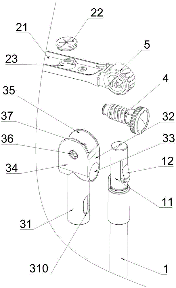
图2为本实用新型角度可调节的清洁工具的局部爆炸结构示意图;Fig. 2 is a schematic diagram of the local explosion structure of the angle-adjustable cleaning tool of the present invention;
图3为本实用新型角度可调节的清洁工具的蜗杆件结构示意图;Fig. 3 is a structural schematic diagram of the worm part of the angle-adjustable cleaning tool of the present invention;
图4为本实用新型角度可调节的清洁工具的传动柱结构示意图;Fig. 4 is a structural schematic diagram of the transmission column of the utility model angle-adjustable cleaning tool;
图5为本实用新型角度可调节的清洁工具的安装部结构示意图。Fig. 5 is a structural schematic diagram of the installation part of the angle-adjustable cleaning tool of the present invention.
附图标记:1操作杆;101安装杆;102弹性按钮;2清洁头;201清洁杆;202定位扣;203定位孔;3安装部;301安装筒;3011安装孔;302连接板;303旋转孔;304第一安装板;305第二安装板;306第一转动孔;307第二转动孔;308支承板;309支撑孔;3091缺槽;4蜗杆件;401蜗杆本体;4011限位凸起;402连接管;403旋钮;404连接杆;405弹性凸起;406凸起配合孔;407限位条;5传动柱;501传动齿;502转动轴;503环槽;504调节穿孔。Reference signs: 1 operation rod; 101 installation rod; 102 elastic button; 2 cleaning head; 201 cleaning rod; 202 positioning buckle; 203 positioning hole; 3 installation part; 301 installation cylinder; 3011 installation hole; Hole; 304 first mounting plate; 305 second mounting plate; 306 first rotating hole; 307 second rotating hole; 308 supporting plate; 309 supporting hole; 3091 missing groove; 4 worm parts; 401 worm body; 402 connecting pipe; 403 knob; 404 connecting rod; 405 elastic protrusion; 406 protrusion matching hole; 407 limit bar; 5 transmission column; 501 transmission tooth;
具体实施方式Detailed ways
下面结合附图和实施例,对本实用新型的具体实施方式作进一步详细描述。以下实施例用于说明本实用新型,但不用来限制本实用新型的范围。Below in conjunction with accompanying drawing and embodiment, the specific embodiment of the utility model is described in further detail. The following examples are used to illustrate the utility model, but not to limit the scope of the utility model.
如图1-5所示,一种角度可调节的清洁工具,包括操作杆1和设置于所述操作杆1一端的清洁头2,还包括蜗杆件4和传动柱5,所述操作杆1用于安装所述清洁头2的一端设置有安装部3,所述蜗杆件4转动设置于所述安装部3上,所述传动柱5也转动设置于所述安装部3上,所述传动柱5的轴线与所述蜗杆件4的轴线相垂直;As shown in Figures 1-5, an angle-adjustable cleaning tool includes an operating rod 1 and a
所述传动柱5的周向外壁至少部分设置有与所述蜗杆件4相啮合的传动齿501,所述传动柱5通过所述传动齿501与所述蜗杆件4传动连接;所述传动柱5的周向外壁与所述清洁头2相连接。The peripheral outer wall of the
具体地,所述操作杆1有多节短杆组成,所述短杆至少设置有两个,相邻的两个短杆之间螺纹连接,用户可根据实际情况组装多节短杆以便于进行打扫;所述传动柱5位于所述蜗杆件4的上方。Specifically, the operating rod 1 is composed of multi-section short rods. There are at least two short rods, and the two adjacent short rods are threaded. Cleaning; the
采用上述结构,所述传动柱5通过所述传动齿501和所述蜗杆件4传动连接,在操作时,转动所述蜗杆件4,所述蜗杆件4带动所述传动柱5转动,进而带动所述清洁头2转动,从而实现无级调节所述清洁头2角度的目的;其中,所述安装部3为所述蜗杆件4和所述传动柱5提供安装空间,以便于将所述清洁头2转动连接在所述操作杆1上。With the above structure, the
进一步地,所述安装部3可拆卸设置于所述操作杆1上。Further, the
采用上述结构,便于用户将所述操作杆1和清洁头2进行拆装。With the above-mentioned structure, it is convenient for the user to disassemble the operating rod 1 and the
进一步地,所述蜗杆件4与所述传动柱5自锁传动配合,即所述蜗杆件4的导程角满足条件时,所述蜗杆件4能够驱动所述传动柱5转动,所述传动柱4无法驱动所述蜗杆件5转动实现自锁。Further, the
采用上述结构,所以蜗杆件4不会受到所述传动柱5影响而转动,进而可以旋转所述蜗杆件4,以实现调节并控制所述清洁头2旋转角度的目的,且不用设置额外的锁定机构进行锁定,结构简单,使用方便。With the above-mentioned structure, the
如图2所示,进一步地,所述安装部3包括安装筒301,所述安装筒301的侧壁贯穿设置有安装孔3011;As shown in Fig. 2, further, the
所述操作杆1的上端设置有安装杆101,所述安装杆101用于插接进所述安装筒301内,所述安装杆101的侧壁设置有弹性按钮102,所述弹性按钮102用于与所述安装孔3011相卡接,且所述弹性按钮102在外力作用下缩进所述安装筒301内部。The upper end of the operating rod 1 is provided with a mounting
具体地,所述安装杆101的侧壁设置有凹槽,所述弹性按钮102包括弹片和凸起钮,所述弹片用于将所述凸起钮连接在所述凹槽的侧壁,正常状态下的所述凸起钮凸出于所述安装杆101的侧壁,当所述凸起钮受到挤压时,所述凸起钮能够缩进所述凹槽内;或者,所述弹片可以用弹簧进行代替。Specifically, the side wall of the
采用上述结构,通过按压所述凸起钮,所述凸起钮挤压所述弹簧或者弹片,使得所述凸起钮缩进所述凹槽内,此时,将所述安装部3套接在所述安装杆101上,并使得所述凸起钮与所述安装孔3011对齐,然后去除对所述凸起钮的外力,所述凸起钮受所述弹簧或者所述弹片的作用复位,而凸出于所述安装杆101的侧壁且通过所述安装孔3011凸出于所述安装筒301的外壁,进而使得所述凸起钮与所述安装孔3011相卡接,使得所述安装部3固定在所述操作杆1上;拆卸时,按压所述凸起钮,所述凸起钮挤压所述弹簧或者弹片,使得所述凸起钮缩进所述凹槽内进而缩进所述安装筒301内部,此时,便于将所述安装部3从所述操作杆1上取下,整个安装于拆卸过程简单便捷。With the above structure, by pressing the protruding button, the protruding button squeezes the spring or the shrapnel, so that the protruding button retracts into the groove, and at this time, the mounting
在一些实施例中,所述安装杆101的直径小于所述安装筒301的直径,所述弹性按钮102包括弹片和凸起钮,所述弹片用于将所述凸起钮连接在所述安装杆101的侧壁,正常状态下的所述凸起钮凸出于所述安装杆101的侧壁;安装时,按压所述凸起钮,所述凸起钮挤压所述弹片,使得所述凸起钮与所述安装杆101紧贴,此时,便于将所述安装部3套接在所述安装杆101和所述凸起钮的外壁,并使得所述凸起钮与所述安装孔3011对齐,然后去除对所述凸起钮的外力,所述凸起钮受所述弹片的作用复位,而凸出于所述安装杆101的侧壁且通过所述安装孔3011凸出于所述安装筒301的外壁,进而使得所述凸起钮与所述安装孔3011相卡接,使得所述安装部3固定在所述操作杆1上;拆卸时,按压所述凸起钮,所述凸起钮挤压所述弹片,使得所述凸起钮缩进安装筒301内部,此时,便于将所述安装部3从所述操作杆1上取下,以实现拆卸的目的。In some embodiments, the diameter of the
进一步地,所述安装部3还括设置相对设置的连接板302和支撑板308,所述连接板302上设置有旋转孔303;所述支承板上设置有支撑孔309,且所述支撑孔309与所述旋转孔303同轴设置;具体的,所述连接板302和支撑板308设置在安装筒301上方。Further, the
如图3所示,所述蜗杆件4包括蜗杆本体401、连接管402和旋钮403,所述连接管402的一端与所述旋钮403固定连接,所述连接管402的另一端与所述蜗杆本体401可拆卸连接,所述连接管402用于贯穿所述旋转孔303并与所述旋转孔303转动连接,所述蜗杆本体远离所述连接管的尾端贯穿所述支撑孔309;As shown in Figure 3, the
所述蜗杆本体的尾端在所述支撑孔309的两侧分别凸起形成限位凸起4011。The tail end of the worm body respectively protrudes from both sides of the
采用上述结构,所述旋转孔303用于安装所述连接管402,所述支撑孔309用于安装所述蜗杆本体401的尾端,以使所述蜗杆本体401固定于所述安装部3上;With the above structure, the
所述限位凸起4011的设置能够限制所述蜗杆件4的轴向运动,所述蜗杆件4的转动更加稳定,与所述传动柱5的传动更加可靠。The setting of the limiting
具体的,所述连接管402和旋钮403为一体件;Specifically, the connecting
所述支撑孔309的半径沿着远离所述连接板302方向逐渐减小,且所述支撑孔309远离所述连接板的一端侧壁上设置有缺槽3091,使得所述支撑孔309的侧壁具有弹性;所述蜗杆本体401的尾端半径沿着远离所述连接板302方向逐渐减小以与所述支撑孔309相匹配;上述结构,便于所述蜗杆本体401的尾端与支撑孔309的安装配合。The radius of the
所述旋钮403通过所述连接管402与所述蜗杆本体401相连接,所述蜗杆本体401安装在所述安装部3内部时,所述旋钮403位于所述安装部3的外壁,以便于用户从外部调节所述旋钮403,以达到调节所述蜗杆本体401的目的。The
所述连接板302和所述支承板相对设置,有利于对所述蜗杆本体401进行支撑,使得所述蜗杆本体401转动设置在所述安装筒301上;其中,所述连接管402的另一端与所述蜗杆本体401可拆卸连接,便于实际生产安装。The connecting
进一步地,所述蜗杆本体401的一端具有连接杆404,所述连接杆404的外壁对称设置有弹性凸起405;Further, one end of the
所述连接管402的侧壁贯穿设置有凸起配合孔406,所述弹性凸起405用于与所述凸起配合孔406相卡接。A protrusion
具体地,所述连接杆404为中空杆,以便于用户通过按压所述弹性凸起405而使所述弹性凸起405缩进所述连接杆404中。Specifically, the connecting
所述连接管402中空的截面形状可以是圆形、三角形、矩形、多边形或者是其组合的各种形状,相应地,所述连接杆404的截面形状也可以是圆形、三角形、矩形、多边形或者是其组合的各种形状,所述连接管402与所述连接杆404配套设置,所述连接杆404用于插接于所述连接管402中。The hollow cross-sectional shape of the connecting
采用上述结构,在将所述蜗杆本体401安装在所述连接管402上时,将所述弹性凸起405朝所述连接杆404内部按压,使得所述弹性凸起405缩进所述连接杆404中,此时,将所述连接杆404插接进所述连接管402中,并使得所述弹性凸起405与所述凸起配合孔406相对齐,然后,所述弹性凸起405复位进而与所述凸起配合孔406相卡接,从而将所述蜗杆本体401固定在所述连接管402上。With the above structure, when the
进一步地,所述连接管402的外壁沿其周向方向均匀设置有多个限位条407,多个所述限位条407所在的圆环的外径与所述旋转孔303的直径相匹配。Further, the outer wall of the connecting
具体地,所述限位条407与所述连接管402的轴线平行设置。Specifically, the limiting
采用上述结构,所述限位条407的设置用于增加所述连接管402与所述旋转孔303之间的摩擦,使得所述旋钮403不会受到外界的环境因素而自行转动,从而有利于提高所述清洁头2与所述操作杆1连接处的稳定性。With the above structure, the setting of the
进一步地,所述安装部3还包括相对设置的第一安装板304和第二安装板305;所述第一安装板304上贯穿设置有第一转动孔306,所述第二安装板305上贯穿设置有第二转动孔307,所述第一转动孔306和所述第二转动孔307直径相同且同轴设置;Further, the
如图4所示,所述传动柱5的两端侧壁中心均设置有转动轴502,两个所述转动轴502分别与所述第一转动孔306、所述第二转动孔307转动连接。As shown in Figure 4, the centers of the side walls at both ends of the
具体的,所述第一转动孔306和所述第二转动孔307的位置高于所述旋转孔303的位置;Specifically, the positions of the
所述第一安装板304和所述第二安装板305设置在安装筒301上方;所述连接板302连接在所述第一安装板304和所述第二安装板305之间,所述支撑板308连接在所述第一安装板304和所述第二安装板305之间。The
采用上述结构,所述第一安装板304和所述第二安装板305的设置为所述传动柱5提供支撑,所述传动柱5两侧的所述转动轴502分别与所述第一转动孔306、所述第二转动孔307转动连接,进而使得所述传动柱5转动设置于所述安装部3上,有利于实现所述传动柱5能够与所述蜗杆本体401的传动连接。With the above structure, the arrangement of the first mounting
进一步地,所述转动轴502的外壁设置有环槽503,所述环槽503的直径与所述第一转动孔306的直径相匹配;Further, the outer wall of the
所述转动轴502上沿其轴向方向设置有调节穿孔504,所述调节穿孔504将所述转动轴502分成两个半轴。The
具体地,两个所述半轴朝向所述调节穿孔504中间靠拢时,两个所述半轴的外端能够穿过所述第一转动孔306,并使得所述第一转动孔306卡接于所述环槽503处。Specifically, when the two half-shafts move toward the middle of the adjustment through
采用上述结构,在安装所述传动柱5时,将两个所述半轴朝向所述调节穿孔504中间按压,使得两个所述半轴朝向所述调节穿孔504中间靠拢,此时,两个半轴的外端能够穿过所述第一转动孔306直到所述环槽503处停止,此时,去除对所述半轴的作用力,两个所述半轴复位,所述第一转动孔306与所述环槽503相卡接,另一个所述转动轴502以同样的方法安装进所述第二转动孔307内,整个安装步骤较为简单,用户能够自行手动将所述传动柱5转动安装在所述安装部3上。With the above structure, when installing the
进一步地,所述清洁头2包括清洁杆201、除尘套和定位扣202,所述清洁杆201与所述传动柱5的周向侧壁固定连接,所述清洁杆201上设有与所述定位扣202相匹配的定位孔203,所述除尘套套接于所述清洁杆201的外壁,所述定位扣202用于隔着所述除尘套与所述定位孔203相卡接。Further, the cleaning
采用上述结构,所述定位扣202和所述定位孔203的设置有利于防止所述除尘套从所述清洁杆201上脱落。With the above structure, the setting of the
具体的,所述传动柱5与所述清洁杆201为一体件。Specifically, the
其中,所述清洁杆201上还设置有螺栓安装孔,并配有相对应的螺栓和螺母;其中,所述螺栓安装孔的设置用于安装刮板、清洁海绵以及其他的清洁件,便于用户根据实际需求进行替换。Wherein, the cleaning
以上所述仅是本实用新型的优选实施方式,应当指出,对于本技术领域的普通技术人员来说,在不脱离本实用新型技术原理的前提下,还可以做出若干改进和润饰,这些改进和润饰也应视为本实用新型的保护范围。The above is only the preferred embodiment of the utility model, and it should be pointed out that for those of ordinary skill in the art, without departing from the technical principle of the utility model, some improvements and modifications can also be made. And retouching should also be regarded as the protection scope of the present utility model.
Claims (10)
Priority Applications (1)
| Application Number | Priority Date | Filing Date | Title |
|---|---|---|---|
| CN202222883978.XU CN219166330U (en) | 2022-10-31 | 2022-10-31 | A cleaning tool with adjustable angle |
Applications Claiming Priority (1)
| Application Number | Priority Date | Filing Date | Title |
|---|---|---|---|
| CN202222883978.XU CN219166330U (en) | 2022-10-31 | 2022-10-31 | A cleaning tool with adjustable angle |
Publications (1)
| Publication Number | Publication Date |
|---|---|
| CN219166330U true CN219166330U (en) | 2023-06-13 |
Family
ID=86668757
Family Applications (1)
| Application Number | Title | Priority Date | Filing Date |
|---|---|---|---|
| CN202222883978.XU Active CN219166330U (en) | 2022-10-31 | 2022-10-31 | A cleaning tool with adjustable angle |
Country Status (1)
| Country | Link |
|---|---|
| CN (1) | CN219166330U (en) |
-
2022
- 2022-10-31 CN CN202222883978.XU patent/CN219166330U/en active Active
Similar Documents
| Publication | Publication Date | Title |
|---|---|---|
| CN210190958U (en) | But angle regulation's drawing board for landscape design | |
| CN107883071A (en) | Rotary joint | |
| CN111473029A (en) | A new type of handle locking pin | |
| CN219166330U (en) | A cleaning tool with adjustable angle | |
| WO2012139488A1 (en) | Telescopic tube for dust collector | |
| CN203641195U (en) | Locking mechanism | |
| CN202719468U (en) | a desk lamp | |
| CN206488428U (en) | Air conditioning wind shield device | |
| CN212136145U (en) | Novel support of dry-type transformer ware body device | |
| CN209643703U (en) | A kind of small-sized household noodle press | |
| CN201575008U (en) | Locking device | |
| CN110695898A (en) | Magnetic telescopic sleeve | |
| CN212479707U (en) | Agricultural machinery pump connection structure | |
| CN211721575U (en) | A 360-degree button-type fish guard adjustment device | |
| CN103741623B (en) | Foliage pressure-vacuum machine airduct fixed disassembly structure-improved | |
| CN108652349B (en) | One kind being convenient for quilt cover more changing device | |
| CN213061433U (en) | Telescopic rod with multipurpose joint | |
| CN222168090U (en) | Mounting structure for household appliance small transformer easy to quickly disassemble and assemble | |
| CN210949419U (en) | A limit structure of a telescopic tube and a garden tool | |
| CN203729232U (en) | Disassembly, assembly, fixation and improvement structure for leaf blower air duct | |
| CN223586955U (en) | Paddle fixing bolt anti-convolution structure | |
| CN220824233U (en) | Telescopic duster | |
| CN221129804U (en) | Mop with replaceable mop cloth | |
| CN222148038U (en) | Installation mechanism of network security management machine | |
| CN214128483U (en) | Hair sticky device convenient to dismantle |
Legal Events
| Date | Code | Title | Description |
|---|---|---|---|
| GR01 | Patent grant | ||
| GR01 | Patent grant | ||
| EE01 | Entry into force of recordation of patent licensing contract | ||
| EE01 | Entry into force of recordation of patent licensing contract |
Assignee: Ningbo Haishu Xinyi Sanitary Ware Co.,Ltd. Assignor: Ningbo Haishu Liangpin Living Goods Co.,Ltd. Contract record no.: X2025980024529 Denomination of utility model: A cleaning tool with an adjustable angle Granted publication date: 20230613 License type: Common License Record date: 20250924 |