EP1679445A1 - Führungselement für ein bewegbares Teil - Google Patents
Führungselement für ein bewegbares Teil Download PDFInfo
- Publication number
- EP1679445A1 EP1679445A1 EP06075002A EP06075002A EP1679445A1 EP 1679445 A1 EP1679445 A1 EP 1679445A1 EP 06075002 A EP06075002 A EP 06075002A EP 06075002 A EP06075002 A EP 06075002A EP 1679445 A1 EP1679445 A1 EP 1679445A1
- Authority
- EP
- European Patent Office
- Prior art keywords
- guide member
- member according
- ceramic elements
- support
- bearing
- Prior art date
- Legal status (The legal status is an assumption and is not a legal conclusion. Google has not performed a legal analysis and makes no representation as to the accuracy of the status listed.)
- Granted
Links
- 239000000919 ceramic Substances 0.000 claims abstract description 47
- 239000000463 material Substances 0.000 claims abstract description 41
- 239000002184 metal Substances 0.000 claims description 9
- 238000007789 sealing Methods 0.000 claims description 7
- 229910001092 metal group alloy Inorganic materials 0.000 claims description 4
- 239000002131 composite material Substances 0.000 claims description 3
- 229920001971 elastomer Polymers 0.000 claims description 3
- 239000000806 elastomer Substances 0.000 claims description 3
- 229920006122 polyamide resin Polymers 0.000 claims description 3
- 229920002379 silicone rubber Polymers 0.000 claims description 3
- 238000002788 crimping Methods 0.000 claims description 2
- 238000013016 damping Methods 0.000 abstract description 5
- 230000000295 complement effect Effects 0.000 abstract description 2
- 235000012431 wafers Nutrition 0.000 description 8
- 230000000694 effects Effects 0.000 description 4
- 238000000465 moulding Methods 0.000 description 3
- 230000035939 shock Effects 0.000 description 3
- 238000010521 absorption reaction Methods 0.000 description 2
- 238000004873 anchoring Methods 0.000 description 2
- 230000000712 assembly Effects 0.000 description 2
- 238000000429 assembly Methods 0.000 description 2
- 230000006378 damage Effects 0.000 description 2
- 239000012530 fluid Substances 0.000 description 2
- 239000007789 gas Substances 0.000 description 2
- 229910000906 Bronze Inorganic materials 0.000 description 1
- 239000004962 Polyamide-imide Substances 0.000 description 1
- 230000004323 axial length Effects 0.000 description 1
- 230000015572 biosynthetic process Effects 0.000 description 1
- 210000004027 cell Anatomy 0.000 description 1
- 239000013043 chemical agent Substances 0.000 description 1
- 238000006243 chemical reaction Methods 0.000 description 1
- 239000011248 coating agent Substances 0.000 description 1
- 238000000576 coating method Methods 0.000 description 1
- 230000036461 convulsion Effects 0.000 description 1
- 230000007547 defect Effects 0.000 description 1
- 238000006073 displacement reaction Methods 0.000 description 1
- 239000002783 friction material Substances 0.000 description 1
- 230000007774 longterm Effects 0.000 description 1
- 239000000314 lubricant Substances 0.000 description 1
- 238000012423 maintenance Methods 0.000 description 1
- 238000004519 manufacturing process Methods 0.000 description 1
- 239000004033 plastic Substances 0.000 description 1
- 229920003023 plastic Polymers 0.000 description 1
- 229920002312 polyamide-imide Polymers 0.000 description 1
- 230000000379 polymerizing effect Effects 0.000 description 1
- 239000012858 resilient material Substances 0.000 description 1
- 239000011347 resin Substances 0.000 description 1
- 229920005989 resin Polymers 0.000 description 1
- 238000005245 sintering Methods 0.000 description 1
- 239000000126 substance Substances 0.000 description 1
- 239000012815 thermoplastic material Substances 0.000 description 1
- 229920001187 thermosetting polymer Polymers 0.000 description 1
- 239000002966 varnish Substances 0.000 description 1
Images


Classifications
-
- F—MECHANICAL ENGINEERING; LIGHTING; HEATING; WEAPONS; BLASTING
- F16—ENGINEERING ELEMENTS AND UNITS; GENERAL MEASURES FOR PRODUCING AND MAINTAINING EFFECTIVE FUNCTIONING OF MACHINES OR INSTALLATIONS; THERMAL INSULATION IN GENERAL
- F16C—SHAFTS; FLEXIBLE SHAFTS; ELEMENTS OR CRANKSHAFT MECHANISMS; ROTARY BODIES OTHER THAN GEARING ELEMENTS; BEARINGS
- F16C17/00—Sliding-contact bearings for exclusively rotary movement
- F16C17/02—Sliding-contact bearings for exclusively rotary movement for radial load only
- F16C17/03—Sliding-contact bearings for exclusively rotary movement for radial load only with tiltably-supported segments, e.g. Michell bearings
-
- F—MECHANICAL ENGINEERING; LIGHTING; HEATING; WEAPONS; BLASTING
- F16—ENGINEERING ELEMENTS AND UNITS; GENERAL MEASURES FOR PRODUCING AND MAINTAINING EFFECTIVE FUNCTIONING OF MACHINES OR INSTALLATIONS; THERMAL INSULATION IN GENERAL
- F16C—SHAFTS; FLEXIBLE SHAFTS; ELEMENTS OR CRANKSHAFT MECHANISMS; ROTARY BODIES OTHER THAN GEARING ELEMENTS; BEARINGS
- F16C17/00—Sliding-contact bearings for exclusively rotary movement
- F16C17/12—Sliding-contact bearings for exclusively rotary movement characterised by features not related to the direction of the load
- F16C17/18—Sliding-contact bearings for exclusively rotary movement characterised by features not related to the direction of the load with floating brasses or brushing, rotatable at a reduced speed
-
- F—MECHANICAL ENGINEERING; LIGHTING; HEATING; WEAPONS; BLASTING
- F16—ENGINEERING ELEMENTS AND UNITS; GENERAL MEASURES FOR PRODUCING AND MAINTAINING EFFECTIVE FUNCTIONING OF MACHINES OR INSTALLATIONS; THERMAL INSULATION IN GENERAL
- F16C—SHAFTS; FLEXIBLE SHAFTS; ELEMENTS OR CRANKSHAFT MECHANISMS; ROTARY BODIES OTHER THAN GEARING ELEMENTS; BEARINGS
- F16C27/00—Elastic or yielding bearings or bearing supports, for exclusively rotary movement
- F16C27/02—Sliding-contact bearings
-
- F—MECHANICAL ENGINEERING; LIGHTING; HEATING; WEAPONS; BLASTING
- F16—ENGINEERING ELEMENTS AND UNITS; GENERAL MEASURES FOR PRODUCING AND MAINTAINING EFFECTIVE FUNCTIONING OF MACHINES OR INSTALLATIONS; THERMAL INSULATION IN GENERAL
- F16C—SHAFTS; FLEXIBLE SHAFTS; ELEMENTS OR CRANKSHAFT MECHANISMS; ROTARY BODIES OTHER THAN GEARING ELEMENTS; BEARINGS
- F16C27/00—Elastic or yielding bearings or bearing supports, for exclusively rotary movement
- F16C27/06—Elastic or yielding bearings or bearing supports, for exclusively rotary movement by means of parts of rubber or like materials
- F16C27/063—Sliding contact bearings
-
- F—MECHANICAL ENGINEERING; LIGHTING; HEATING; WEAPONS; BLASTING
- F16—ENGINEERING ELEMENTS AND UNITS; GENERAL MEASURES FOR PRODUCING AND MAINTAINING EFFECTIVE FUNCTIONING OF MACHINES OR INSTALLATIONS; THERMAL INSULATION IN GENERAL
- F16C—SHAFTS; FLEXIBLE SHAFTS; ELEMENTS OR CRANKSHAFT MECHANISMS; ROTARY BODIES OTHER THAN GEARING ELEMENTS; BEARINGS
- F16C33/00—Parts of bearings; Special methods for making bearings or parts thereof
- F16C33/02—Parts of sliding-contact bearings
- F16C33/04—Brasses; Bushes; Linings
- F16C33/043—Sliding surface consisting mainly of ceramics, cermets or hard carbon, e.g. diamond like carbon [DLC]
Definitions
- the present invention relates to a guide member of a movable part, for example of a shaft or a cylindrical rod movable in rotation and / or in translation, or a rotulante piece.
- rings made of metal or metal alloy such as a bronze alloy, with in some cases a surface varnish to improve the sliding of the shaft.
- rings generally used dry without additional lubricant, are made of a piece of plastic material or comprise a metal support or liner ensuring the mechanical strength, with a coating of the guide surfaces by a low friction material.
- these rings are subjected to severe constraints, for example high pressure, high sliding speed or high temperature, often with vibrations or shocks transmitted by the shaft to be guided, which results in rapid wear and risk of destruction of these rings.
- metal rings are used to reduce wear and increase service life, it is seizing problems that can be seen in the long term.
- these rings are produced by sintering, which makes it easy to produce complex shapes.
- they have the disadvantage of having a very high stiffness, zero elasticity and fragility to shock, which poses resistance problems because these rings do not deform and in case of wear, the surfaces in contact are degraded and a play of operation appears, which can lead to the rupture of the rings.
- the present invention is intended to provide a simple and effective solution to these problems.
- It relates to a guide member with a low coefficient of friction and very good resistance to wear, and also having a resilience allowing it to accept a certain deformation and withstand high mechanical stresses.
- a hollow guide member of a movable part comprising at least one internal surface intended to come into contact with friction and sliding and an external surface (14) of friction and sliding, characterized in that the The contact surfaces of this guide member consist of separate ceramic elements carried by a support having resilience and damping characteristics.
- An essential advantage of the guide member according to the invention is that it combines a high hardness of the contact surface with the moving part and a certain resilience that allows it to accept a deformation without risk of rupture.
- the contact surface is split and formed of elements separated from each other which can be deformed independently, so that this contact surface can suffer without disadvantages different local stresses.
- the support of the ceramic elements is of elastically deformable material and is advantageously molded or overmoulded on these elements.
- the support is shaped before mounting the ceramic elements and is for example constituted of a metal cage or the like.
- the ceramic elements may have protruding shapes for their attachment to the support by crimping or clipping.
- the support of the ceramic elements is slightly set back relative to the surface defined by these elements, which prevents the support from rubbing on the moving part.
- the ceramic elements may be either in contact with both the moving part and with a device for supporting this part, which makes it possible to reduce the number of elements, for example in the case of a small guide member. , either in contact with only the moving part or with only the support device, which ensures a greater elasticity of the guide member.
- the guide member according to the invention can take various forms. It may constitute a cylindrical sleeve of revolution adapted to guide a shaft or a cylindrical rod and comprise either ceramic elements extending over substantially the entire length of the sleeve in the axial direction, or elements arranged successively on the length of the sleeve, these successive elements being angularly offset relative to each other.
- the cylindrical sleeve comprises at one of its ends a flange formed by the support and may comprise ceramic elements on at least one of its faces.
- the guide member according to the invention may also be a washer comprising ceramic plates on at least one of its faces, for example for the axial support of a rotary shaft.
- the guiding member according to the invention may also be a guide ball of a moving part following a swiveling movement, this ball comprising ceramic elements defining a spherical surface.
- the guide member comprises a sleeve or a sleeve on its face opposite to that defined by the ceramic elements.
- the support of the ceramic elements can advantageously contribute to the achievement of a seal with the moving part or with its support device, either directly by cooperation of shapes, or indirectly via a joint sealing.
- the support of the ceramic elements is for example a silicone elastomer RTV type, which withstands high temperatures of the order of 300 ° C, a metal alloy, a composite material, a polyamide resin, resistant to high temperatures.
- An interesting application of the invention is an anti-friction sleeve for guiding a rotation of a blade with variable angular setting of a turbojet engine.
- the guide member according to the invention is a sliding bearing 1 for guiding in rotation and / or in translation of a shaft or a cylindrical rod. It has a cylindrical shape of revolution having an internal surface for guiding the shaft.
- This bearing comprises two inner and outer coaxial assemblies, of at least three ceramic elements each, defining an internal cylindrical surface of friction and sliding contact and an outer cylindrical surface of friction and sliding contact.
- a first set consists of internal elements 2, the second set consists of external elements 4, formed by parallelepiped ceramic plates.
- the inner plates 2 are of constant cross section, defined by an inner circular arc 6 and an outer circular arc 8. These arcs have the same center located on the axis of the bearing 1 and they are interconnected at their ends by a curved side forming a projecting angle 10. These inner plates 2 are evenly distributed around the axis of the bearing, at 120 degrees from each other.
- the radii of the inner arches 6 are equal and the inner surfaces 12 of the plates 2 define an inner cylindrical surface 22 for guiding a shaft (not shown).
- the outer plates 4 likewise have a parallelepipedal shape elongated along the axis of the bearing, with a constant section comprising an outer circular arc 16. These outer plates 4 are evenly distributed around the axis of the bearing, 120 degrees from each other. They are shifted transversely 60 degrees relative to the inner plates 2. The radii of the outer arches 16 are equal and the outer surfaces 14 of the plates 4 define an outer cylindrical surface 24 for guiding or fixing the bearing 1 on a non-supporting device. represent.
- the plates 2, 4 are interconnected by a bonding material 20 which fills the entire volume left free, between the inner cylindrical surfaces 22 and outer 24.
- This bonding material is slightly set back from the inner cylindrical surfaces 22 and outer 24 of the bearing 18, this withdrawal for example of a few tenths of a millimeter having the effect of ensuring that the connecting material 20 does not come into contact with the shaft to guide or with the support device.
- the bonding material ensures the positioning and the connection between them of the various plates 2 and 4, by adhesion of the bonding material 20 to the wafers.
- This connection can also be supplemented by a mechanical latching effect in the case where the plates comprise surfaces with negative draft or undercut, such as for example the projecting angle 10, for anchoring or embedding these plates in the connecting material 20.
- a simple solution consists in over-molding the material in a mold in which the platelets have been positioned.
- the bonding material 20 fills all the free space of the molding volume by ensuring good contact with the surfaces of the wafers.
- This material may be a thermoplastic material, thermosetting or polymerizing by chemical reaction.
- various known means can be used, such as for example platelet surface improving the attachment of the bonding material.
- this material is chosen to have a certain resilience or elasticity and may be made of elastomer, for example silicone elastomer of the RTV type already used in aeronautics and which holds at temperatures of the order of 300 ° C., or in an polyamide-imide resin.
- This bearing is used as follows. Its inner cylindrical surface 12 is fitted to the surface of the guide shaft, which is in contact with hard ceramic surfaces providing effective guiding with a low coefficient of friction and low wear.
- the resilience of the bonding material 20 ensuring the maintenance of the wafers provides a particular advantage.
- These very rigid plates by themselves are maintained in a slightly flexible manner by a material which has qualities of damping and energy absorption.
- the internal friction surface of the bearing has a certain ability to conform by following geometry defects resulting from the wear of the materials in contact, which avoids the formation of areas of high pressure that could be seen in the case of a rigid guide member.
- the connecting material 20 allows the inner cylindrical surface 22 to locally deform by relative displacement of the wafers, without resulting in high stresses. In addition, this resilience allows an energy absorption which can be interesting in the case where the guided shaft transmits vibrations or jerks.
- Another advantage of this bearing is its ability to adapt to the holding device. When the outer cylindrical surface of the bearing is mounted tight in a bore, it can absorb manufacturing tolerances without generating high stresses.
- the outer cylindrical surface of the bearing can also serve as a guiding and friction surface with the same characteristics and advantages as its internal cylindrical surface. It is the same for the axial end faces of the bearing which can be used for axial positioning of the guided shaft.
- the bearing can therefore be fixed on a support device or left free between two parts in relative movement.
- FIGS. 4 to 6 show an alternative embodiment of the bearing, in which, in a similar manner, ceramic plates 30 held by a connecting material 20 are six in number and are not offset radially but circumferentially relative to each other; to others.
- the plates 30 each have a length or axial dimension less than half the axial length of the bearing and are divided into two axially superimposed stages, the one-level plates being offset by 60 ° with respect to the pads of the other stage around of the bearing axis.
- Each plate 30 has an elongate shape in a cylinder portion along the axis of the bearing 32 and has an inner cylindrical face 34 and an outer cylindrical face 36, which are centered on the axis of the bearing. These cylindrical faces are interconnected by dihedral side faces with a projecting angle 38.
- the inner faces 34 of the plates define the same cylindrical surface of revolution constituting the guide surface of a shaft and the outer faces 36 of these plates define the cylindrical outer surface of the bearing.
- the wafers are carried and held by a bonding material 20 of the aforementioned type.
- the two end faces 40 of the bearing are constituted solely by the connecting material 20, unlike the bearing of FIG. 2.
- An advantage of this variant is to create additional sealing by a baffle due to the angularly offset arrangement of the plates between the two stages.
- a fluid passage can be expected between the shaft and the inner cylindrical surface 22 of the bearing. This passage is easier in the case of the bearing of FIG. 2, the surface 22 of which comprises rectilinear channels formed between the plates by the slightly recessed connecting material, these channels being parallel to the axis and extending over the entire length of the landing.
- the angularly offset arrangement of the wafers in the two stages creates a baffling effect which forces the fluid to bypass the obstacle and can limit its flow rate.
- FIG. 8 Another variant is shown in Figures 7 to 9 and corresponds to a combination of the two previous embodiments.
- the bearing 58 of FIG. 8 comprises two axially superimposed platen stages as in FIG. 5 and each of these stages itself comprises a set of inner plates 50, 54 and a set of external plates 52, 56, the inner plates being identical. between them, and the outer plates being identical to each other, the numbers of inner plates and outer plates being eight, in the example shown.
- the internal faces of the inner plates 50, 54 and the outer faces of the outer plates 52, 56 respectively form an internal surface and a cylindrical outer surface of friction or connection with a moving part and with a support device.
- the lateral faces of the platelets have an undercut shape for mechanical anchoring of the platelets in the bonding material.
- the outer plates 52 have an angular extent greater than that of the inner plates, which increases the share of the ceramic in the outer cylindrical surface of the bearing. Moreover, the lateral faces of these plates are flat and radial and do not provide mechanical attachment in the bonding material, except by adhesion.
- the bearings of Figures 1 to 6 have for example an internal diameter of the order of 10mm while those of Figures 7 to 10 may have an internal diameter greater than 15mm.
- FIG. 11 represents a variant of the bearing of FIGS. 1 to 3 which comprises two inner and outer coaxial assemblies respectively of three plates 2, 4, supported by the connecting material 20 which additionally forms a flange at an axial end of the bearing.
- This flange can have several functions: it can serve as a bearing face fixed to a support of the bearing, its larger surface facilitating the connection. It can also be itself filled with ceramic plates on a flat face, platelets held in the same manner by adhesion or by a mechanical attachment effect on the bonding material. It can also be used for the support and friction of an axially guided rotary shaft, with a large surface to reduce the contact pressures.
- This collar can also be used for sealing.
- a sealing element such as a seal by the face of the flange facing towards the support, the other flat face of the collar serving or no friction face.
- sealing means may be provided on the bearing according to the invention, for example by using the molding of the bonding material to give it complex shapes for sealing by contact, forming a baffle or by intermediate of a complementary element such as a fixed or rotating joint.
- FIG. 12 represents an example of use of a sliding bearing according to the invention, for the pivoting mounting of a blade 70 with variable angular setting in a turbo-reactor.
- These blades are used to straighten a gas flow at high temperature, and are subject to severe constraints (high temperature, chemical compatibility with gases, high loads). The system must remain completely reliable for the entire period of use between revisions, without play or risk of breakage.
- the blade 70 is guided in a chimney 74 of a housing 72 by a bearing 88 which allows a pivoting movement of the blade 70 while ensuring its axial stalling.
- the angular position of the blade 70 is controlled by a link 78 fixed rigidly on the tail 76 of the blade 70.
- the other end of the control rod 78 is driven by a control ring 82 by means of a metal finger 84 guided in a bushing 90 mounted on the ring 82, which acts simultaneously on different links to control the set of blades 70 of at least one rectifying stage.
- the blade root guiding bearing 86 comprises a collar bushing 106 corresponding to the embodiment of FIG. 11 and a washer 94.
- the axially elongated portion of the bushing 92 is inserted into a bore of the chimney 74 and comprises internal plates 104 and external 98, carried by a connecting material of the aforementioned type.
- the axial guidance of the vane 70 relative to the casing 72 is provided with low friction and good reliability by the collar 106 of the sleeve 92 and the washer 94.
- the flange 106 comprises ceramic plates 100 forming a flat surface annular bearing on the control rod 78 and ensuring friction therewith.
- the washer 94 also comprises ceramic plates 102 forming an annular flat surface bearing on a shoulder formed at the junction between the tail 76 and the blade 70.
- This axial guidance is mounted with a reduced axial functional clearance or with a slight prestressing axial. This guidance is, like the rotation guide, subjected to pressure and shock. The use of ceramic boards mounted on a resilient material is therefore quite appropriate.
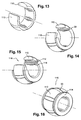
- FIGS 13 to 16 show an alternative embodiment relating to a ball joint having a spherical guide surface.
- This ball joint comprises a series of identical ceramic plates 110, with a regular angular distribution around an axis and a circumferential clearance between them.
- the inner faces of these plates 110 define a cylindrical surface and their outer faces define a sphere segment surface.
- These plates each have two plane lateral faces between their spherical and cylindrical faces.
- a guide member according to the invention consists of ceramic plates separated from each other and carried by a material having a certain resilience and a damping capacity.
- a material having a certain resilience and a damping capacity for example a metal alloy, a composite, a polyamide resin, an elastomer or the like.
- the wafers described above have friction surfaces with a generally rectangular contour, but could have different contours, for example rounded.
Landscapes
- Engineering & Computer Science (AREA)
- General Engineering & Computer Science (AREA)
- Mechanical Engineering (AREA)
- Physics & Mathematics (AREA)
- Fluid Mechanics (AREA)
- Chemical & Material Sciences (AREA)
- Ceramic Engineering (AREA)
- Sliding-Contact Bearings (AREA)
- Structures Of Non-Positive Displacement Pumps (AREA)
Applications Claiming Priority (1)
| Application Number | Priority Date | Filing Date | Title |
|---|---|---|---|
| FR0500097A FR2880394B1 (fr) | 2005-01-06 | 2005-01-06 | Organe de guidage d'une piece mobile |
Publications (2)
| Publication Number | Publication Date |
|---|---|
| EP1679445A1 true EP1679445A1 (de) | 2006-07-12 |
| EP1679445B1 EP1679445B1 (de) | 2007-06-13 |
Family
ID=34953439
Family Applications (1)
| Application Number | Title | Priority Date | Filing Date |
|---|---|---|---|
| EP06075002A Active EP1679445B1 (de) | 2005-01-06 | 2006-01-04 | Führungselement für ein bewegbares Teil |
Country Status (5)
| Country | Link |
|---|---|
| US (1) | US7695194B2 (de) |
| EP (1) | EP1679445B1 (de) |
| DE (1) | DE602006000018T2 (de) |
| FR (1) | FR2880394B1 (de) |
| RU (1) | RU2314442C2 (de) |
Cited By (2)
| Publication number | Priority date | Publication date | Assignee | Title |
|---|---|---|---|---|
| EP1870600B1 (de) * | 2006-06-21 | 2016-09-14 | SNECMA Services | Lager für den Drehzapfen einer Leitschaufel einer Turbomaschine mit variablem Einstellwinkel, zugehörige Leitschaufel und Turbomaschine |
| EP4184028A1 (de) * | 2021-11-18 | 2023-05-24 | Getzner Werkstoffe Holding GmbH | Lagereinrichtung zum schwingungsisolierenden lagern einer maschine |
Families Citing this family (8)
| Publication number | Priority date | Publication date | Assignee | Title |
|---|---|---|---|---|
| KR100862060B1 (ko) | 2007-04-10 | 2008-10-09 | 류충오 | 복합재료 드라이브 샤프트 제작용 몰드 및 이를 이용하여제작한 복합재료 드라이브 샤프트 |
| CN103851077B (zh) * | 2014-03-14 | 2016-03-16 | 北京航空航天大学 | 一种零刚度柔性轴承 |
| WO2016097283A1 (en) | 2014-12-19 | 2016-06-23 | Saint-Gobain Performance Plastics Pampus Gmbh | Bearing comprising discrete sliding components and head restraint comprising such bearing |
| US9732791B1 (en) | 2015-02-25 | 2017-08-15 | Us Synthetic Corporation | Bearing assemblies including tilting bearing elements and superhard sliding bearing elements, bearing assemblies including a substantially continuous bearing element and superhard sliding bearing elements, and related bearing apparatuses and methods |
| WO2019020385A1 (en) | 2017-07-14 | 2019-01-31 | Saint-Gobain Performance Plastics Pampus Gmbh | PIN, PIN ASSEMBLY, AND METHOD OF MANUFACTURE AND USE THEREOF |
| JP7290254B2 (ja) | 2018-07-02 | 2023-06-13 | ソニーセミコンダクタソリューションズ株式会社 | 変換ケーブル及び電子機器 |
| CN111441239B (zh) * | 2020-04-15 | 2021-06-18 | 上海建工建材科技集团股份有限公司 | 一种预制盖梁预应力深埋锚套筒及其安装工艺 |
| US11293488B1 (en) | 2021-07-02 | 2022-04-05 | Alfredo A. Ciotola | Compressively resilient bushing |
Citations (8)
| Publication number | Priority date | Publication date | Assignee | Title |
|---|---|---|---|---|
| GB499928A (en) * | 1937-04-17 | 1939-01-31 | Giovanni Trione | Improvements relating to bearings with floating bushes |
| US3390926A (en) * | 1966-08-24 | 1968-07-02 | Wallace Murray Corp | Combined journal and thrust bearing |
| US3902771A (en) * | 1974-03-26 | 1975-09-02 | Us Navy | Rubber stave bearing which will permit slow speed motion without stick-slip and resultant squeal |
| US3920293A (en) * | 1974-04-23 | 1975-11-18 | Hirokazu Takeuchi | Bearing made of plastics |
| US4664595A (en) * | 1983-09-30 | 1987-05-12 | Ebara Corporation | Combination of slide members |
| DE4226986A1 (de) * | 1992-08-14 | 1994-02-17 | Audi Ag | Gelenk, insbesondere Kugelgelenk |
| US5800068A (en) * | 1996-09-16 | 1998-09-01 | Wanger; Gerhard | Spindle for gas bearing of a rapidly rotating tool |
| US6024494A (en) * | 1998-02-12 | 2000-02-15 | Ingersoll-Dresser Pump Company | Polymer-backed thrust bearings |
Family Cites Families (18)
| Publication number | Priority date | Publication date | Assignee | Title |
|---|---|---|---|---|
| US2758892A (en) * | 1951-06-11 | 1956-08-14 | Wallgren August Gunn Ferdinand | Radial thrust bearing |
| US3428374A (en) * | 1966-04-13 | 1969-02-18 | Kaman Corp | Self-lubricating bearing |
| US3578828A (en) * | 1969-02-18 | 1971-05-18 | Kaman Aerospace Corp | Split-race bearing construction |
| US3604768A (en) * | 1969-09-08 | 1971-09-14 | Cincinnati Milacron Inc | Bearing shoe construction |
| US3711171A (en) * | 1969-12-08 | 1973-01-16 | Kacarb Products Corp | Ceramic bearings |
| GB1280596A (en) * | 1970-03-09 | 1972-07-05 | Aerostatic Ltd | Fluid pad bearings |
| DE3014645C2 (de) * | 1980-04-16 | 1982-12-02 | MTU Motoren- und Turbinen-Union München GmbH, 8000 München | Metall-Keramik-Bauteil und Verfahren zu seiner Herstellung |
| US4515486A (en) * | 1984-02-03 | 1985-05-07 | Ide Russell D | Elastomeric supported hydrodynamic bearing |
| US4526482A (en) * | 1984-02-07 | 1985-07-02 | Ide Russell D | Hydrodynamic bearing surface for high loads and low viscosity lubricating fluids |
| JPS63314372A (ja) * | 1987-06-15 | 1988-12-22 | Hitachi Ltd | 水車の水潤滑軸受装置 |
| US5033871A (en) * | 1988-10-25 | 1991-07-23 | Ide Russell D | Extrudable multi-rigidity hydrodynamic bearing and method of making the same |
| US5017022A (en) * | 1988-11-09 | 1991-05-21 | Allied-Signal, Inc. | High temperature bearing |
| JPH0814284B2 (ja) * | 1989-02-02 | 1996-02-14 | 株式会社ウイング・ハイセラ | セラミックス製軸受 |
| US5006043A (en) * | 1989-11-20 | 1991-04-09 | Sundstrand Corporation | Floating annular seal with thermal compensation |
| US5458460A (en) * | 1993-03-18 | 1995-10-17 | Hitachi, Ltd. | Drainage pump and a hydraulic turbine incorporating a bearing member, and a method of manufacturing the bearing member |
| JPH07238924A (ja) * | 1994-02-28 | 1995-09-12 | Fuji Xerox Co Ltd | 動圧空気軸受 |
| JP3318531B2 (ja) * | 1998-08-04 | 2002-08-26 | ミネベア株式会社 | 回転電機及びその軸受構造 |
| JP3698001B2 (ja) * | 2000-03-14 | 2005-09-21 | Jfeスチール株式会社 | 連続溶融金属めっき浴中ロール用すべり軸受装置 |
-
2005
- 2005-01-06 FR FR0500097A patent/FR2880394B1/fr not_active Expired - Fee Related
- 2005-12-28 US US11/319,133 patent/US7695194B2/en active Active
- 2005-12-28 RU RU2005141460/11A patent/RU2314442C2/ru active
-
2006
- 2006-01-04 DE DE602006000018T patent/DE602006000018T2/de active Active
- 2006-01-04 EP EP06075002A patent/EP1679445B1/de active Active
Patent Citations (8)
| Publication number | Priority date | Publication date | Assignee | Title |
|---|---|---|---|---|
| GB499928A (en) * | 1937-04-17 | 1939-01-31 | Giovanni Trione | Improvements relating to bearings with floating bushes |
| US3390926A (en) * | 1966-08-24 | 1968-07-02 | Wallace Murray Corp | Combined journal and thrust bearing |
| US3902771A (en) * | 1974-03-26 | 1975-09-02 | Us Navy | Rubber stave bearing which will permit slow speed motion without stick-slip and resultant squeal |
| US3920293A (en) * | 1974-04-23 | 1975-11-18 | Hirokazu Takeuchi | Bearing made of plastics |
| US4664595A (en) * | 1983-09-30 | 1987-05-12 | Ebara Corporation | Combination of slide members |
| DE4226986A1 (de) * | 1992-08-14 | 1994-02-17 | Audi Ag | Gelenk, insbesondere Kugelgelenk |
| US5800068A (en) * | 1996-09-16 | 1998-09-01 | Wanger; Gerhard | Spindle for gas bearing of a rapidly rotating tool |
| US6024494A (en) * | 1998-02-12 | 2000-02-15 | Ingersoll-Dresser Pump Company | Polymer-backed thrust bearings |
Cited By (2)
| Publication number | Priority date | Publication date | Assignee | Title |
|---|---|---|---|---|
| EP1870600B1 (de) * | 2006-06-21 | 2016-09-14 | SNECMA Services | Lager für den Drehzapfen einer Leitschaufel einer Turbomaschine mit variablem Einstellwinkel, zugehörige Leitschaufel und Turbomaschine |
| EP4184028A1 (de) * | 2021-11-18 | 2023-05-24 | Getzner Werkstoffe Holding GmbH | Lagereinrichtung zum schwingungsisolierenden lagern einer maschine |
Also Published As
| Publication number | Publication date |
|---|---|
| RU2005141460A (ru) | 2007-07-20 |
| DE602006000018D1 (de) | 2007-07-26 |
| FR2880394A1 (fr) | 2006-07-07 |
| EP1679445B1 (de) | 2007-06-13 |
| US7695194B2 (en) | 2010-04-13 |
| DE602006000018T2 (de) | 2008-02-21 |
| FR2880394B1 (fr) | 2008-07-04 |
| US20060147139A1 (en) | 2006-07-06 |
| RU2314442C2 (ru) | 2008-01-10 |
Similar Documents
| Publication | Publication Date | Title |
|---|---|---|
| EP1679445B1 (de) | Führungselement für ein bewegbares Teil | |
| CA2621730C (fr) | Commande des aubes a angle de calage variable | |
| EP2926029B1 (de) | Untersetzungsgetriebe mit einem verschlussstopfen zur axialen stützung einer feder zur absorption des getriebespiels | |
| FR2776350A1 (fr) | Dispositif de debrayage a autocentrage | |
| FR2725259A1 (fr) | Bague d'etancheite activee par pression | |
| EP1767799A1 (de) | Gleitlagervorrichtung für Welle und entsprechende Welle und Motor | |
| EP1188933A1 (de) | Steuervorrichtung für verstellbare Leitschaufeln | |
| EP1439308A1 (de) | Verschliessschutzvorrichtung für verstellbare Schaufeln einer Turbomaschine | |
| EP4363312A1 (de) | Dichtungsanordnung für ein fliehkraftbelastetes wälzlager | |
| EP1925868A1 (de) | Wasserdichte Verbindungseinrichtung | |
| EP1068437B1 (de) | Betätigungsvorrichtung für die schwenkbare schubdüse eines strahltriebwerks mit mehreren in umfangsrichtung verteilten elastischen bauteilen | |
| EP3705684B1 (de) | Rotor für eine gegenläufige turbine einer turbomaschine | |
| FR2993947A1 (fr) | Organe de liaison rotule perfectionne | |
| FR2897639A1 (fr) | Dispositif anti-usure pour systeme de calage variable d'aube d'une turbomachine | |
| EP4219967B1 (de) | Gelenkkomponente und solche enthaltendes mechanisches system | |
| EP2327893B1 (de) | Wellenlagereinheit für Welle eines Wellenkraftwerks, und eine solche Wellenlagereinheit umfassendes Wellenkraftwerk | |
| FR2560945A1 (fr) | Joints ou paliers flexibles comprenant un element exterieur composite | |
| EP3653894B1 (de) | Verbindungsstück, das zwei ineinandergreifende teile umfasst, die zusammengebaut sind, und entsprechendes herstellungsverfahren | |
| FR2784711A1 (fr) | Dispositif de commande d'aubes a angle de calage variable | |
| FR3083836A1 (fr) | Composant articulé, et système mécanique comprenant un tel composant | |
| FR3052820B1 (fr) | Piston pour une machine hydraulique a pistons radiaux a frottements limites | |
| FR3016672A1 (fr) | Dispositif d'etancheite, notamment pour une vanne ou un raccord | |
| FR3126017A1 (fr) | Module de soufflante a pales a calage variable | |
| FR2644858A1 (fr) | Joint d'etancheite pour roulement | |
| FR2720108A1 (fr) | Echangeur thermique rotatif et turbine à gaz associée. |
Legal Events
| Date | Code | Title | Description |
|---|---|---|---|
| PUAI | Public reference made under article 153(3) epc to a published international application that has entered the european phase |
Free format text: ORIGINAL CODE: 0009012 |
|
| 17P | Request for examination filed |
Effective date: 20060120 |
|
| AK | Designated contracting states |
Kind code of ref document: A1 Designated state(s): AT BE BG CH CY CZ DE DK EE ES FI FR GB GR HU IE IS IT LI LT LU LV MC NL PL PT RO SE SI SK TR |
|
| AX | Request for extension of the european patent |
Extension state: AL BA HR MK YU |
|
| GRAP | Despatch of communication of intention to grant a patent |
Free format text: ORIGINAL CODE: EPIDOSNIGR1 |
|
| GRAS | Grant fee paid |
Free format text: ORIGINAL CODE: EPIDOSNIGR3 |
|
| AKX | Designation fees paid |
Designated state(s): DE FR GB |
|
| GRAA | (expected) grant |
Free format text: ORIGINAL CODE: 0009210 |
|
| AK | Designated contracting states |
Kind code of ref document: B1 Designated state(s): DE FR GB |
|
| REG | Reference to a national code |
Ref country code: GB Ref legal event code: FG4D Free format text: NOT ENGLISH |
|
| GBT | Gb: translation of ep patent filed (gb section 77(6)(a)/1977) |
Effective date: 20070613 |
|
| REF | Corresponds to: |
Ref document number: 602006000018 Country of ref document: DE Date of ref document: 20070726 Kind code of ref document: P |
|
| PLBE | No opposition filed within time limit |
Free format text: ORIGINAL CODE: 0009261 |
|
| STAA | Information on the status of an ep patent application or granted ep patent |
Free format text: STATUS: NO OPPOSITION FILED WITHIN TIME LIMIT |
|
| 26N | No opposition filed |
Effective date: 20080314 |
|
| REG | Reference to a national code |
Ref country code: FR Ref legal event code: PLFP Year of fee payment: 11 |
|
| REG | Reference to a national code |
Ref country code: FR Ref legal event code: PLFP Year of fee payment: 12 |
|
| REG | Reference to a national code |
Ref country code: FR Ref legal event code: PLFP Year of fee payment: 13 |
|
| REG | Reference to a national code |
Ref country code: FR Ref legal event code: CD Owner name: SAFRAN AIRCRAFT ENGINES Effective date: 20170719 |
|
| PGFP | Annual fee paid to national office [announced via postgrant information from national office to epo] |
Ref country code: GB Payment date: 20231219 Year of fee payment: 19 |
|
| PGFP | Annual fee paid to national office [announced via postgrant information from national office to epo] |
Ref country code: FR Payment date: 20231219 Year of fee payment: 19 |
|
| PGFP | Annual fee paid to national office [announced via postgrant information from national office to epo] |
Ref country code: DE Payment date: 20231219 Year of fee payment: 19 |