EP1679252A1 - Connection for a car frame - Google Patents
Connection for a car frame Download PDFInfo
- Publication number
- EP1679252A1 EP1679252A1 EP05100064A EP05100064A EP1679252A1 EP 1679252 A1 EP1679252 A1 EP 1679252A1 EP 05100064 A EP05100064 A EP 05100064A EP 05100064 A EP05100064 A EP 05100064A EP 1679252 A1 EP1679252 A1 EP 1679252A1
- Authority
- EP
- European Patent Office
- Prior art keywords
- cross member
- connection
- arrangement according
- attachment
- region
- Prior art date
- Legal status (The legal status is an assumption and is not a legal conclusion. Google has not performed a legal analysis and makes no representation as to the accuracy of the status listed.)
- Withdrawn
Links
Images


Classifications
-
- B—PERFORMING OPERATIONS; TRANSPORTING
- B62—LAND VEHICLES FOR TRAVELLING OTHERWISE THAN ON RAILS
- B62D—MOTOR VEHICLES; TRAILERS
- B62D21/00—Understructures, i.e. chassis frame on which a vehicle body may be mounted
- B62D21/11—Understructures, i.e. chassis frame on which a vehicle body may be mounted with resilient means for suspension, e.g. of wheels or engine; sub-frames for mounting engine or suspensions
Definitions
- the invention relates to a body joint assembly with a longitudinal beam and with a cross member, which are connected to each other and abut each other in the region of the compound.
- Body joint assemblies of the above type are common in motor vehicles, especially passenger cars (PKW) and therefore known. They usually include laterally arranged and extending in the longitudinal direction of the vehicle side members, which are connected via approximately transversely thereto extending cross member. These are usually welded together at the joints where the beams abut each other.
- a motor vehicle rear frame in which two longitudinal members are connected to one another by a rear axle cross member.
- a respective end face partially closing elbow is welded at each end of the cross member, which in turn is welded to the outside of the longitudinal member.
- a reinforcing sheet is welded below the connecting gap against the undersides of the beams.
- DE 195 07 767 C2 discloses a vehicle chassis subframe mounting structure in which a cross member is arranged between lateral side members, wherein an additional carrier is fixed to the connecting portions between the longitudinal members and cross member.
- the cross member and the respective side member adjoin each other without overlapping.
- a nut member for fixing a subframe for other components is arranged.
- a cross member as part of a motor vehicle floor group is known from DE 100 22 916 A1. This has on both sides in the connection area depending on a mounting area for screwing a rear axle unit and an adjacent spring receiving area for fixing a coil spring.
- a stiffening structure is provided in the connection area formed by box-shaped interleaved steel sheets.
- the strength of body joint assemblies in the field of seat and / or seat belt fasteners in the ground area of importance since they are exposed to very high loads in the event of a crash.
- the seat and / or seat belt fasteners are bolted to the vehicle floor, which is reinforced with additional sheets.
- the reinforcing plates can in turn be spot-welded to the rear axle cross member, so that the occurring forces can be distributed to the longitudinal members via the axle cross member.
- the connection point or connection arrangement of the cross member with the respective side member is heavily loaded.
- welding points may break between the cross member and the side member.
- connection points or connection arrangements In bodies and therefore also in their connection arrangements, there is thus a desire to carry them out with a high strength of the connection points or connection arrangements in spite of simple and cost-effective production and low weight and high rigidity.
- the carriers in the region of the connection overlap one another and an attachment for a vehicle part is arranged in the overlapping region of the connection and thus engages one of the two carriers and at least bears against the other carrier, that the strength of the region of the connection through the made Attachment of the vehicle part is increased, it is possible to solidify the connection arrangement with simple and inexpensive production and low weight and high rigidity.
- the usually already existing attachment for a vehicle part is thus in the overlapping region of the compound the carrier relocates. This is achieved without additional reinforcement plates or reinforced components.
- longitudinal members are to be understood in the longitudinal direction of the vehicle-oriented carrier, in particular those of the bottom group of the body.
- the cross member is accordingly at an angle of about 90 ° thereto, so approximately transversely to aligned carrier such.
- B is an axle cross member.
- the angle in the region of the connection between the carriers can be in the order of about 60 to 120 °, depending on the design of the carrier in detail.
- crossbeams initially form a deviating from 90 ° angle only in the region of the connection to the longitudinal member, the overall alignment of the carrier to each other, however, is still approximately transversely or perpendicular to each other.
- the cross member overlaps the side rail.
- the cross member surrounds the longitudinal member so that it is "wound around" the longitudinal member, so that a particularly strong and at the same time rigid connection arrangement is achieved.
- the cross member is a seat cross member, a rear seat cross member, an axle cross member, a Schuachsquerthe or a subframe of the chassis or suspension suspension or a cross member.
- a seat cross member a rear seat cross member
- an axle cross member a Deutschenachsquerthe or a subframe of the chassis or suspension suspension or a cross member.
- a Deutschenachsquerthe a subframe of the chassis or suspension suspension or a cross member.
- B. in the subframe of a Achsquerliess or chassis is the case. These are particularly suitable because they are usually designed to be particularly stable.
- cross member seat and / or seat belt fasteners are arranged in a further embodiment.
- the force introduced in the event of a crash can be transmitted or distributed without interruption via the cross member to the longitudinal members and to the further vehicle part, which is fastened in the overlapping region of the connection.
- ECE 14 and ECE 17 test conditions there is no danger of tearing out (see above).
- vehicle part is part of the chassis so that these structurally stable vehicle parts absorb part of the introduced forces. It also reduces the displacement of the body panels under the ECE 14 and ECE 17 test conditions.
- the attachment passes through the side rail and is applied to the cross member or the attachment passes through both the longitudinal member and the cross member. These arrangements further increase the strength of the connection assembly and allow easy fixing of the attachment.
- the attachment is a sleeve which is preferably fixed in the upper of the two supports (usually the side members). Also, the sleeve can be supported at least on the lower support. It makes sense if the sleeve is a threaded sleeve, so that z. B. the chassis part can be attached by screwing.
- the chassis part is a part of the suspension chassis and screwed by means of attachment to the cross member and side member.
- FIGS. 1 and 2 a respective perspective view of a connecting arrangement of a passenger vehicle body designated as a whole by 1 in the region of a connection of a cross member 2 with a longitudinal member 3 from above or from below is shown.
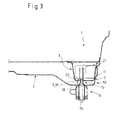
- Figures 3 and 4 show sections through the region of the connection with bolted axle suspension. It is understood that, although only one side of the cross member 2 is shown and will be described, the other side of the cross member 2 is constructed accordingly and the cross member 2 connects two laterally arranged side members 3 together.
- the cross member 2 is in this case a Wegachsquerany, which is constructed of an approximately U-shaped upwardly open plate.
- the cross member 2 comprises along the longitudinal sides in each case a bent-over edge 6.
- the cross member 2 further comprises beads 7 and indentations or bulges 8 for increasing the rigidity and strength and / or for adaptation to other vehicle parts, not shown.
- a seat and / or seat belt fastening plate 4 is welded to which any seat and / or seat belt fastenings can be made through a floor panel.
- the longitudinal member 3 is aligned approximately in the longitudinal direction of the vehicle and also has an approximately U-shaped cross section and along the longitudinal sides in each case a bent edge 9.
- the longitudinal beam 3 can also beads and indentations or bulges to increase the stiffness and strength and / or have to adapt to other not shown vehicle parts.
- the cross member 2 overlaps the longitudinal member 3, d. H. lies in Figure 1 (seen from above) with its edges 6 from below to this.
- the cross member and the side member thus overlap in the area of their connection.
- the cross member 2 is connected to the longitudinal member 3 in the usual way via welds.
- the cross member 2 engages around the side member 3 on its end face 10, thus resting against its outside 11 with a bent region 12.
- the cross member 2 jumps in the region of the connection to the longitudinal member 3 back or down, so that the upper edges of the edges 6, 9 of the two carriers 2, 3 form approximately a common plane for a floor panel.
- the connection arrangement 1 further comprises a fastening 5 for a vehicle part, which is arranged in the overlapping region of the connection.
- the vehicle part is a subframe 14 of the rear axle suspension, which is not shown for clarity.
- the attachment 5 is designed as a threaded sleeve 16, with which the subframe 14 is screwed by means of a corresponding threaded screw 15.
- the lower cross member 2 has a corresponding bore 13, as shown in particular in FIGS. 3 and 4.
- the threaded sleeve 16 is widened at the lower end 17, so that it is supported on the lower inner side 18 of the cross member 2 around the circumference of the bore 13 and may possibly be welded there. Above this, the threaded sleeve 16 has a threaded portion 19 for receiving the threaded screw 15.
- the threaded sleeve 16 extends upwardly and passes through a recess 20 provided in the underside of the longitudinal member 3. Above and inside the longitudinal member 3, the threaded sleeve 16 is fixed to a metal sheet 21 arranged between the side walls of the longitudinal member 3 , This can be z. B. done by welding.
- connection assembly 1 Due to the additional connection of the two carriers 2, 3 via the attachment 5 so the connection assembly 1 is amplified.
- the originating from the seat and / or seat belt fasteners forces on the mounting plates 4 to the cross member 2 and from there to the side member 3 and the attachment 5 or threaded sleeve 16 are also passed to the subframe 14 of the axle suspension.
Abstract
Description
Die Erfindung betrifft eine Karosserieverbindungsanordnung mit einem Längsträger und mit einem Querträger, die mit einander verbunden sind und an einander im Bereich der Verbindung anliegen.The invention relates to a body joint assembly with a longitudinal beam and with a cross member, which are connected to each other and abut each other in the region of the compound.
Karosserieverbindungsanordnungen der vorstehenden Art sind bei Kraftfahrzeugen, insbesondere Personenkraftfahrzeugen (PKW) üblich und daher bekannt. Sie umfassen meist seitlich angeordnete und in Längsrichtung des Fahrzeugs verlaufende Längsträger, die über etwa quer dazu verlaufende Querträger verbunden sind. Diese sind üblicherweise an den Verbindungsstellen, wo die Träger aneinander angrenzen, miteinander verschweißt.Body joint assemblies of the above type are common in motor vehicles, especially passenger cars (PKW) and therefore known. They usually include laterally arranged and extending in the longitudinal direction of the vehicle side members, which are connected via approximately transversely thereto extending cross member. These are usually welded together at the joints where the beams abut each other.
Aus der DE 195 22 219 A1 ist ein Kraftfahrzeug-Hinterrahmen bekannt, bei dem zwei Längsträger durch einen Hinterachs-Querträger miteinander verbunden sind. Hierzu ist an jedem Ende des Querträgers ein seine jeweilige Stirnseite teilweise verschließendes Winkelstück eingeschweißt, das wiederum mit der Außenseite des Längsträgers verschweißt ist. Ein Verstärkungsblech ist unterhalb des Verbindungsspalts gegen die Unterseiten der Träger geschweißt.From DE 195 22 219 A1 a motor vehicle rear frame is known in which two longitudinal members are connected to one another by a rear axle cross member. For this purpose, a respective end face partially closing elbow is welded at each end of the cross member, which in turn is welded to the outside of the longitudinal member. A reinforcing sheet is welded below the connecting gap against the undersides of the beams.
Die DE 195 07 767 C2 offenbart einen Fahrzeugchassis-Unterrahmen-Montageaufbau, bei dem zwischen seitlichen Längsträgern ein Querträger angeordnet ist, wobei ein zusätzlicher Träger an den Verbindungsabschnitten zwischen Längsträgern und Querträger festgelegt ist. Der Querträger und der jeweilige Längsträger grenzen dabei an einander ohne Überlappung an. Durch den zusätzlichen Träger und den Querträger ist ein Mutterelement zur Befestigung eines Unterrahmens für weitere Bauteile angeordnet.DE 195 07 767 C2 discloses a vehicle chassis subframe mounting structure in which a cross member is arranged between lateral side members, wherein an additional carrier is fixed to the connecting portions between the longitudinal members and cross member. The cross member and the respective side member adjoin each other without overlapping. By the additional carrier and the cross member a nut member for fixing a subframe for other components is arranged.
Ein Querträger als Teil einer Kraftfahrzeug-Bodengruppe ist aus der DE 100 22 916 A1 bekannt. Dieser weist beidseitig im Verbindungsbereich je einen Befestigungsbereich zum Anschrauben einer Hinterachseinheit und einen benachbarten Federaufnahmebereich zur Fixierung einer Schraubenfeder auf. Zusätzlich ist eine Versteifungsstruktur im Verbindungsbereich vorgesehen, die von kastenförmigen ineinander verschachtelten Stahlblechen gebildet wird.A cross member as part of a motor vehicle floor group is known from DE 100 22 916 A1. This has on both sides in the connection area depending on a mounting area for screwing a rear axle unit and an adjacent spring receiving area for fixing a coil spring. In addition, a stiffening structure is provided in the connection area formed by box-shaped interleaved steel sheets.
Insbesondere ist die Festigkeit von Karosserieverbindungsanordnungen im Bereich der Sitz- und/oder Sicherheitsgurtbefestigungen im Bodenbereich von Bedeutung, da diese im Crashfall sehr hohen Belastungen ausgesetzt sind. Oft sind die Sitz- und/oder Sicherheitsgurtbefestigungen am Fahrzeugboden verschraubt, der mit zusätzlichen Blechen verstärkt ist. Die Verstärkungsbleche können wiederum an dem hinteren Achsquerträger Punktverschweißt sein, so dass die auftretenden Kräfte über den Achsquerträger auf die Längsträger verteilt werden können. Hierbei wird die Verbindungsstelle bzw. Verbindungsanordnung des Querträgers mit dem jeweiligen Längsträger stark belastet. Trotz der Verstärkungsbleche kann es so unter den ECE 14 und ECE 17 Testbedingungen zu einem Ausreißen der Schweißpunkte zwischen dem Querträger und dem Längsträger kommen.In particular, the strength of body joint assemblies in the field of seat and / or seat belt fasteners in the ground area of importance, since they are exposed to very high loads in the event of a crash. Often the seat and / or seat belt fasteners are bolted to the vehicle floor, which is reinforced with additional sheets. The reinforcing plates can in turn be spot-welded to the rear axle cross member, so that the occurring forces can be distributed to the longitudinal members via the axle cross member. Here, the connection point or connection arrangement of the cross member with the respective side member is heavily loaded. Despite the reinforcing plates, under the ECE 14 and ECE 17 test conditions, welding points may break between the cross member and the side member.
Bei Karosserien und daher auch bei ihren Verbindungsanordnungen besteht somit der Wunsch, diese mit einer hohen Festigkeit der Verbindungsstellen oder Verbindungsanordnungen auszuführen trotz einfacher und kostengünstiger Herstellung sowie niedrigem Gewicht und hoher Steifheit.In bodies and therefore also in their connection arrangements, there is thus a desire to carry them out with a high strength of the connection points or connection arrangements in spite of simple and cost-effective production and low weight and high rigidity.
Diese Aufgabe wird durch die in Anspruch 1 und 15 angegebene Erfindung gelöst.This object is achieved by the invention defined in
Dadurch, dass die Träger im Bereich der Verbindung einander überlappen und eine Befestigung für ein Fahrzeugteil im überlappenden Bereich der Verbindung angeordnet ist und dabei derart einen der beiden Träger durchgreift und an dem anderen Träger zumindest anliegt, dass die Festigkeit des Bereichs der Verbindung durch die vorgenommene Befestigung des Fahrzeugteils erhöht wird, ist es möglich die Verbindungsanordnung bei einfacher und kostengünstiger Herstellung sowie niedrigem Gewicht und hoher Steifigkeit zu verfestigen. Die üblicherweise ohnehin vorhandene Befestigung für ein Fahrzeugteil wird also in den überlappenden Bereich der Verbindung der Träger verlagert. Dies wird ohne zusätzliche Verstärkungsbleche oder verstärkten Bauteilen erreicht.Due to the fact that the carriers in the region of the connection overlap one another and an attachment for a vehicle part is arranged in the overlapping region of the connection and thus engages one of the two carriers and at least bears against the other carrier, that the strength of the region of the connection through the made Attachment of the vehicle part is increased, it is possible to solidify the connection arrangement with simple and inexpensive production and low weight and high rigidity. The usually already existing attachment for a vehicle part is thus in the overlapping region of the compound the carrier relocates. This is achieved without additional reinforcement plates or reinforced components.
Als Längsträger sind in Längsrichtung des Fahrzeugs ausgerichtete Träger zu verstehen, insbesondere solche der Bodengruppe der Karosserie. Der Querträger ist entsprechend ein in einem Winkel von etwa 90°dazu, also etwa quer dazu, ausgerichteter Träger, wie z. B ein Achsquerträger. Der Winkel im Bereich der Verbindung zwischen den Trägern kann in einer Größenordnung von etwa 60 bis 120° liegen, je nach Ausführung der Träger im Einzelnen. So ist es bekannt, dass Querträger lediglich im Bereich der Verbindung mit dem Längsträger zunächst einen vom 90° abweichenden Winkel ausbilden, die Gesamtausrichtung der Träger zueinander jedoch trotzdem etwa quer bzw. rechtwinklig zueinander ist.As longitudinal members are to be understood in the longitudinal direction of the vehicle-oriented carrier, in particular those of the bottom group of the body. The cross member is accordingly at an angle of about 90 ° thereto, so approximately transversely to aligned carrier such. B is an axle cross member. The angle in the region of the connection between the carriers can be in the order of about 60 to 120 °, depending on the design of the carrier in detail. Thus, it is known that crossbeams initially form a deviating from 90 ° angle only in the region of the connection to the longitudinal member, the overall alignment of the carrier to each other, however, is still approximately transversely or perpendicular to each other.
In einer Ausführungsform der Erfindung überlappt der Querträger den Längsträger. Insbesondere ist es günstig, wenn der Querträger den Längsträger umgreift also quasi um den Längsträger "gewickelt" ist, so dass eine besonders feste und zugleich steife Verbindungsanordnung erreicht wird.In one embodiment of the invention, the cross member overlaps the side rail. In particular, it is advantageous if the cross member surrounds the longitudinal member so that it is "wound around" the longitudinal member, so that a particularly strong and at the same time rigid connection arrangement is achieved.
Als Querträger kommen übliche Querträger in Betracht. Vorteilhafterweise ist der Querträger ein Sitzquerträger, ein hinterer Sitzquerträger, ein Achsquerträger, ein Hinterachsquerträger oder ein Hilfsrahmen des Fahrwerks oder der Fahrwerksaufhängung oder eines Querträgers. So wie dies z. B. bei dem Hilfsrahmen eines Achsquerträgers oder Fahrwerks der Fall ist. Diese bieten sich besonders an, da sie üblicherweise besonders stabil ausgeführt sind.As a cross member usual cross member into consideration. Advantageously, the cross member is a seat cross member, a rear seat cross member, an axle cross member, a Hinterachsquerträger or a subframe of the chassis or suspension suspension or a cross member. As such. B. in the subframe of a Achsquerträgers or chassis is the case. These are particularly suitable because they are usually designed to be particularly stable.
Am Querträger sind in einer weiteren Ausführungsform Sitz- und/oder Sicherheitsgurtbefestigungen angeordnet. So kann die im Crashfall eingeleitete Kraft ohne Unterbrechung über den Querträger an die Längsträger und an das weitere Fahrzeugteil weiter gegeben bzw. verteilt werden, das im überlappenden Bereich der Verbindung befestigt ist. Somit besteht unter den ECE 14 und ECE 17 Testbedingungen keine Gefahr des Ausreißens (vgl. oben).On the cross member seat and / or seat belt fasteners are arranged in a further embodiment. Thus, the force introduced in the event of a crash can be transmitted or distributed without interruption via the cross member to the longitudinal members and to the further vehicle part, which is fastened in the overlapping region of the connection. Thus, under ECE 14 and ECE 17 test conditions, there is no danger of tearing out (see above).
Es bietet sich an, dass das Fahrzeugteil ein Teil des Fahrwerks ist, so dass diese konstruktiv stabilen Fahrzeugteile einen Teil der eingeleiteten Kräfte aufnehmen. Auch wird so die Verlagerung der Karosserieteile unter den ECE 14 und ECE 17 Testbedingungen verringert.It makes sense that the vehicle part is part of the chassis so that these structurally stable vehicle parts absorb part of the introduced forces. It also reduces the displacement of the body panels under the ECE 14 and ECE 17 test conditions.
Vorzugsweise durchgreift die Befestigung den Längsträger und liegt an dem Querträger an oder die Befestigung durchgreift sowohl den Längsträger als auch den Querträger. Auch diese Anordnungen erhöhen die Festigkeit der Verbindungsanordnung weiter und erlauben eine einfache Festlegung der Befestigung.Preferably, the attachment passes through the side rail and is applied to the cross member or the attachment passes through both the longitudinal member and the cross member. These arrangements further increase the strength of the connection assembly and allow easy fixing of the attachment.
In einer Ausführungsform der Karosserieverbindungsanordnung ist die Befestigung eine Hülse, die vorzugsweise in dem oberen der beiden Träger (meist der Längsträger) festgelegt ist. Auch kann sich die Hülse zumindest an dem unteren Träger abstützen. Sinnvoll ist es, wenn die Hülse eine Gewindehülse ist, so dass z. B. das Fahrwerksteil durch Verschrauben befestigt werden kann.In one embodiment of the body connection arrangement, the attachment is a sleeve which is preferably fixed in the upper of the two supports (usually the side members). Also, the sleeve can be supported at least on the lower support. It makes sense if the sleeve is a threaded sleeve, so that z. B. the chassis part can be attached by screwing.
In einer bevorzugten Ausführungsform ist das Fahrwerksteil ein Teil der Fahrwerksaufhängung und mittels der Befestigung mit dem Querträger und Längsträger verschraubbar.In a preferred embodiment, the chassis part is a part of the suspension chassis and screwed by means of attachment to the cross member and side member.
Weitere Merkmale, Einzelheiten und Vorteile der Erfindung ergeben sich aus den Unteransprüchen und der nachfolgenden Beschreibung eines Ausführungsbeispieles anhand der Zeichnung. Es zeigen:
- Fig. 1
- eine perspektivische Ansicht auf eine Verbindungsanordnung im Bereich einer Verbindung eines Querträgers mit einem Längsträger von oben;
- Fig. 2
- eine perspektivische Ansicht auf die Verbindungsanordnung aus Fig. 1 von unten;
- Fig. 3
- einen Schnitt durch die Verbindungsanordnung der Fig. 1 entlang der Längsrichtung des Querträgers mit verschraubter Achsaufhängung und
- Fig.4
- einen Schnitt durch die Verbindungsanordnung der Fig. 3 entlang der Längsrichtung des Längsträgers.
- Fig. 1
- a perspective view of a connection arrangement in the region of a compound of a cross member with a longitudinal beam from above;
- Fig. 2
- a perspective view of the connector assembly of Figure 1 from below.
- Fig. 3
- 1 along the longitudinal direction of the cross member with bolted axle suspension and
- Figure 4
- a section through the connection arrangement of Fig. 3 along the longitudinal direction of the longitudinal member.
In den Figuren 1 und 2 ist eine jeweils perspektivische Ansicht auf eine als Ganzes mit 1 bezeichnete Verbindungsanordnung einer Personenkraftwagenkarosserie im Bereich einer Verbindung eines Querträgers 2 mit einem Längsträger 3 von oben bzw. von unten gezeigt. Figuren 3 und 4 zeigen Schnitte durch den Bereich der Verbindung mit verschraubter Achsaufhängung. Es versteht sich, dass, obwohl nur eine Seite des Querträgers 2 dargestellt ist und beschrieben werden wird, die andere Seite des Querträgers 2 entsprechend aufgebaut ist und der Querträger 2 zwei seitlich angeordnete Längsträger 3 miteinander verbindet.In FIGS. 1 and 2, a respective perspective view of a connecting arrangement of a passenger vehicle body designated as a whole by 1 in the region of a connection of a
Die Bezeichnungen oben bzw. unten beziehen sich auf die Ausrichtung bezüglich der Fahrzeughochachse bei üblicher Ausrichtung des Fahrzeugs, also z. B. im Stand.The names above or below refer to the orientation with respect to the vehicle's vertical axis in the usual orientation of the vehicle, so z. B. in the state.
Der Querträger 2 ist im vorliegenden Fall ein Hinterachsquerträger, der aus einem etwa U-förmigen nach oben offenen Blech aufgebaut ist. Der Querträger 2 umfasst entlang der Längsseiten jeweils einen umgebogenen Rand 6. Der Querträger 2 weist weiterhin Sicken 7 und Ein- bzw. Ausbuchtungen 8 zur Erhöhung der Steifheit und Festigkeit und/oder zur Anpassung an weitere nicht gezeigte Fahrzeugteile auf. An einem der Ränder 6 ist ein Sitz- und/oder Sicherheitsgurtbefestigungsblech 4 angeschweißt, an dem etwaige Sitz- und/oder Sicherheitsgurtbefestigungen durch ein Bodenblech hindurch vorgenommen werden können.The
Der Längsträger 3 ist etwa in Längsrichtung des Fahrzeugs ausgerichtet und besitzt ebenfalls einen etwa U-förmigen Querschnitt sowie entlang der Längsseiten jeweils einen umgebogenen Rand 9. Der Längsträger 3 kann ebenfalls Sicken und Ein- bzw. Ausbuchtungen zur Erhöhung der Steifheit und Festigkeit und/oder zur Anpassung an weitere nicht gezeigte Fahrzeugteile aufweisen.The
An der Stirnseite überlappt der Querträger 2 den Längsträger 3, d. h. liegt in Figur 1 (von oben besehen) mit seinen Rändern 6 von unten an diesem an. Der Querträger und der Längsträger überlappen sich also im Bereich der ihrer Verbindung. Der Querträger 2 ist dabei mit dem Längsträger 3 in üblicher Weise über Schweißpunkte verbunden.At the front side of the
Wie aus Figur 2 und insbesondere Figur 3 ersichtlich ist, umgreift der Querträger 2 an seiner Stirnseite 10 den Längsträger 3, liegt also an dessen Außenseite 11 mit einem umgebogenen Bereich 12 an. Dazu springt der Querträger 2 im Bereich der Verbindung mit dem Längsträger 3 zurück bzw. nach unten, so dass die Oberkanten der Ränder 6, 9 der beiden Träger 2, 3 etwa eine gemeinsame Ebene für ein Bodenblech ausbilden.As can be seen from FIG. 2 and in particular FIG. 3, the
Die Verbindungsanordnung 1 umfasst ferner eine Befestigung 5 für ein Fahrzeugteil, die im überlappenden Bereich der Verbindung angeordnet ist. Im vorliegenden Fall ist das Fahrzeugteil ein Hilfsrahmen 14 der hinteren Achsaufhängung, die zur besseren Übersicht nicht dargestellt ist. Die Befestigung 5 ist als Gewindehülse 16 ausgebildet, mit der der Hilfsrahmen 14 mittels einer entsprechenden Gewindeschraube 15 verschraubt wird. Dazu weist der unten liegende Querträger 2 eine entsprechende Bohrung 13 auf, wie insbesondere aus Fig. 3 und 4 hervorgeht.The
Die Gewindehülse 16 ist am unteren Ende 17 verbreitert, so dass sie sich an der unteren Innenseite 18 des Querträgers 2 um den Umfang der Bohrung 13 abstützt und dort ggf. verschweißt werden kann. Oberhalb dessen weist die Gewindehülse 16 einen Gewindebereich 19 zur Aufnahme der Gewindeschraube 15 auf.The threaded sleeve 16 is widened at the
Von der Innenseite 18 des Querträgers 2 erstreckt sich die Gewindehülse 16 nach oben und durchgreift eine in der Unterseite des Längsträgers 3 vorgesehene Ausnehmung 20. Oberhalb derer und innerhalb des Längsträgers 3 ist die Gewindehülse 16 an einem zwischen den Seitenwänden des Längsträgers 3 angeordneten Blech 21 festgelegt. Dies kann z. B. durch Schweißen erfolgen.Above the
Durch die zusätzliche Verbindung der beiden Träger 2, 3 über die Befestigung 5 wird also die Verbindungsanordnung 1 verstärkt.Due to the additional connection of the two
Somit können die von den Sitz- und/oder Sicherheitsgurtbefestigungen stammenden Kräfte über die Befestigungsbleche 4 an den Querträger 2 und von dort an den Längsträger 3 und über die Befestigung 5 bzw. Gewindehülse 16 auch an den Hilfsrahmen 14 der Achsaufhängung weitergeben werden.Thus, the originating from the seat and / or seat belt fasteners forces on the mounting
- 11
- Verbindungsanordnungjoint assembly
- 22
- Querträgercrossbeam
- 33
- Längsträgerlongitudinal beams
- 44
- Sitz- und/oder SicherheitsgurtbefestigungsblechSeat and / or seat belt mounting plate
- 55
- Befestigungattachment
- 66
- Randedge
- 77
- SickeBeading
- 88th
- Ein- bzw. AusbuchtungIndentation or bulge
- 99
- Randedge
- 1010
- Stirnseite des QuerträgersFront side of the cross member
- 1111
- Außenseiteoutside
- 1212
- umgebogener Bereichbent area
- 1313
- Bohrungdrilling
- 1414
- Hilfsrahmensubframe
- 1515
- Gewindeschraubescrew
- 1616
- Gewindehülsethreaded sleeve
- 1717
- unteres Ende der Gewindehülselower end of the threaded sleeve
- 1818
- untere Innenseite des Querträgerslower inside of the cross member
- 1919
- Gewindebereich der GewindehülseThreaded area of the threaded sleeve
- 2020
- Ausnehmungrecess
- 2121
- Blechsheet
Claims (15)
dadurch gekennzeichnet, daß
die Träger (2, 3) im Bereich der Verbindung einander überlappen und eine Befestigung (5, 16) für ein Fahrzeugteil (14) im überlappenden Bereich der Verbindung angeordnet ist und dabei derart einen der beiden Träger (3) durchgreift und an dem anderen Träger (2) zumindest anliegt, dass die Festigkeit des Bereichs der Verbindung durch die vorgenommene Befestigung des Fahrzeugteils (14) erhöht wird.Body connection arrangement (1), in particular for a motor vehicle, with a side member (3) and with a cross member (2), which are connected to one another and abut each other in the region of the connection,
characterized in that
the supports (2, 3) in the region of the connection overlap one another and an attachment (5, 16) for a vehicle part (14) is arranged in the overlapping region of the connection, thereby passing through one of the two supports (3) and on the other support (2) at least that the strength of the area of the connection is increased by the attachment of the vehicle part (14).
dadurch gekennzeichnet, daß
die Befestigung (5, 16) den Längsträger (3) durchgreift und an dem Querträger (2) anliegt.Bodywork connection arrangement according to claim 1,
characterized in that
the attachment (5, 16) engages through the longitudinal member (3) and bears against the cross member (2).
dadurch gekennzeichnet, daß
die Befestigung (5, 16) sowohl den Längsträger (3) als auch den Querträger (2) durchgreift.Bodywork connection arrangement according to claim 1,
characterized in that
the attachment (5, 16) engages both the longitudinal member (3) and the cross member (2).
dadurch gekennzeichnet, dass
das Fahrzeugteil ein Teil des Fahrwerks (14) ist.Body joint arrangement according to one of claims 1 to 3,
characterized in that
the vehicle part is a part of the chassis (14).
dadurch gekennzeichnet, dass
der Querträger (2) ein Sitzquerträger, ein hinterer Sitzquerträger, ein Achsquerträger, ein Hinterachsquerträger, ein Hilfsrahmen (14) des Fahrwerks oder der Fahrwerksaufhängung oder eines Querträgers ist.Bodywork connection arrangement according to one of claims 1 to 4,
characterized in that
the cross member (2) is a seat cross member, a rear seat cross member, an axle cross member, a Hinterachsquerträger, a subframe (14) of the chassis or the suspension chassis or a cross member.
dadurch gekennzeichnet, dass
am Querträger (2) Sitz- und/oder Sicherheitsgurtbefestigungen (4) angeordnet sind.Bodywork connection arrangement according to one of claims 1 to 5,
characterized in that
on the cross member (2) seat and / or seat belt fasteners (4) are arranged.
dadurch gekennzeichnet, dass
der Querträger (2) den Längsträger (3) überlappt.Body joint arrangement according to one of claims 1 to 6,
characterized in that
the cross member (2) overlaps the side member (3).
dadurch gekennzeichnet, dass
der Querträger (2) den Längsträger (3) umgreift.Body joint arrangement according to one of claims 1 to 7,
characterized in that
the cross member (2) engages around the longitudinal member (3).
dadurch gekennzeichnet, dass
die Befestigung (5) eine Hülse (16) ist.Body joint arrangement according to one of claims 1 to 8,
characterized in that
the attachment (5) is a sleeve (16).
dadurch gekennzeichnet, dass
die Hülse (16) in dem oberen der beiden Träger, insbesondere Längsträger (3), festgelegt ist.Body joint arrangement according to claim 9,
characterized in that
the sleeve (16) in the upper of the two carriers, in particular longitudinal member (3) is fixed.
dadurch gekennzeichnet, dass
die Hülse (16) sich zumindest an dem unteren Träger (2) abstützt.Body connection arrangement according to claim 9 or 10,
characterized in that
the sleeve (16) is supported at least on the lower support (2).
dadurch gekennzeichnet, dass
die Hülse eine Gewindehülse (16) ist.Bodywork connection arrangement according to one of claims 9 to 11,
characterized in that
the sleeve is a threaded sleeve (16).
dadurch gekennzeichnet, dass
die Befestigung (5, 16) über ein Blech (21) in dem oberen Träger (3) festgelegt ist.Body joint arrangement according to one of claims 1 to 12,
characterized in that
the attachment (5, 16) is fixed via a plate (21) in the upper support (3).
dadurch gekennzeichnet, dass
das Fahrwerksteil ein Teil der Fahrwerksaufhängung (14) ist und mittels der Befestigung (5, 16) mit dem Querträger (2) und Längsträger (3) verschraubbar ist.Body joint arrangement according to one of claims 1 to 13,
characterized in that
the chassis part is a part of the chassis suspension (14) and by means of the attachment (5, 16) with the cross member (2) and the longitudinal member (3) can be screwed.
dadurch gekennzeichnet, dass
die Träger (2, 3) im Bereich der Verbindung einander überlappend angeordnet werden und eine Befestigung (5, 16) für ein Fahrzeugteil (14) im überlappenden Bereich der Verbindung angeordnet wird und dabei derart einen der beiden Träger (3) durchgreift und an dem anderen Träger (2) zumindest anliegt, dass die Festigkeit des Bereichs der Verbindung durch die vorgenommene Befestigung des Fahrzeugteils (14) erhöht wird.Method for increasing the strength of a bodywork connection arrangement (1), in particular according to one of the preceding claims, a crossbeam (2) and a longitudinal member (3), which are connected to one another and abut each other in the region of the connection,
characterized in that
the carriers (2, 3) are arranged overlapping one another in the region of the connection and an attachment (5, 16) for a vehicle part (14) is arranged in the overlapping region of the connection and thereby passes through one of the two carriers (3) and on the other carrier (2) at least rests that the strength of the region of the compound is increased by the attachment of the vehicle part (14).
Priority Applications (1)
| Application Number | Priority Date | Filing Date | Title |
|---|---|---|---|
| EP05100064A EP1679252A1 (en) | 2005-01-06 | 2005-01-06 | Connection for a car frame |
Applications Claiming Priority (1)
| Application Number | Priority Date | Filing Date | Title |
|---|---|---|---|
| EP05100064A EP1679252A1 (en) | 2005-01-06 | 2005-01-06 | Connection for a car frame |
Publications (1)
| Publication Number | Publication Date |
|---|---|
| EP1679252A1 true EP1679252A1 (en) | 2006-07-12 |
Family
ID=34938492
Family Applications (1)
| Application Number | Title | Priority Date | Filing Date |
|---|---|---|---|
| EP05100064A Withdrawn EP1679252A1 (en) | 2005-01-06 | 2005-01-06 | Connection for a car frame |
Country Status (1)
| Country | Link |
|---|---|
| EP (1) | EP1679252A1 (en) |
Cited By (3)
| Publication number | Priority date | Publication date | Assignee | Title |
|---|---|---|---|---|
| CN102530083A (en) * | 2011-12-31 | 2012-07-04 | 重庆长安汽车股份有限公司 | Welded assembly of lower cross beam of car |
| DE102015208898B3 (en) * | 2015-05-13 | 2016-08-25 | Volkswagen Aktiengesellschaft | Mounting system and axle auxiliary frame |
| CN112477986A (en) * | 2020-11-27 | 2021-03-12 | 大运汽车股份有限公司 | Front auxiliary frame left-rear mounting assembly structure |
Citations (4)
| Publication number | Priority date | Publication date | Assignee | Title |
|---|---|---|---|---|
| JPH06171553A (en) * | 1992-12-04 | 1994-06-21 | Nissan Motor Co Ltd | Rear suspension mounting part structure for car body floor |
| DE4329532A1 (en) * | 1993-06-01 | 1995-03-09 | Porsche Ag | Motor vehicle |
| US20030160415A1 (en) * | 2002-02-22 | 2003-08-28 | Ki-Chang Kim | Rear suspension connecting part structure under the floor of a vehicle |
| EP1415896A2 (en) * | 2002-11-01 | 2004-05-06 | Fuji Jukogyo Kabushiki Kaisha | Rear structure of vehicle body |
-
2005
- 2005-01-06 EP EP05100064A patent/EP1679252A1/en not_active Withdrawn
Patent Citations (4)
| Publication number | Priority date | Publication date | Assignee | Title |
|---|---|---|---|---|
| JPH06171553A (en) * | 1992-12-04 | 1994-06-21 | Nissan Motor Co Ltd | Rear suspension mounting part structure for car body floor |
| DE4329532A1 (en) * | 1993-06-01 | 1995-03-09 | Porsche Ag | Motor vehicle |
| US20030160415A1 (en) * | 2002-02-22 | 2003-08-28 | Ki-Chang Kim | Rear suspension connecting part structure under the floor of a vehicle |
| EP1415896A2 (en) * | 2002-11-01 | 2004-05-06 | Fuji Jukogyo Kabushiki Kaisha | Rear structure of vehicle body |
Non-Patent Citations (1)
| Title |
|---|
| PATENT ABSTRACTS OF JAPAN vol. 018, no. 503 (M - 1677) 21 September 1994 (1994-09-21) * |
Cited By (3)
| Publication number | Priority date | Publication date | Assignee | Title |
|---|---|---|---|---|
| CN102530083A (en) * | 2011-12-31 | 2012-07-04 | 重庆长安汽车股份有限公司 | Welded assembly of lower cross beam of car |
| DE102015208898B3 (en) * | 2015-05-13 | 2016-08-25 | Volkswagen Aktiengesellschaft | Mounting system and axle auxiliary frame |
| CN112477986A (en) * | 2020-11-27 | 2021-03-12 | 大运汽车股份有限公司 | Front auxiliary frame left-rear mounting assembly structure |
Similar Documents
| Publication | Publication Date | Title |
|---|---|---|
| EP1744945B1 (en) | Motor vehicle | |
| DE602005003737T2 (en) | Vehicle underbody or substructure or structure | |
| EP2547574B1 (en) | Front end of a vehicle | |
| DE102011051481B4 (en) | Bumper arrangement for a motor vehicle | |
| DE102010034932A1 (en) | Motor vehicle body with structurally reinforced front frame connection | |
| DE102008015221A1 (en) | Structure of a rear portion of a motor vehicle body | |
| DE102010051256A1 (en) | Motor vehicle body with reinforcing structure | |
| DE102016209186B3 (en) | Body structure for a motor vehicle | |
| DE102009050495A1 (en) | subframe | |
| DE102016223216A1 (en) | Body floor structure for a vehicle | |
| EP0591715A2 (en) | Industrial vehicle, especially lorry with forward-mounted cab | |
| EP1525133B1 (en) | Floor-stiffening structure in motor vehicles | |
| EP3239022A1 (en) | Platform system | |
| DE102019207486A1 (en) | Body floor structure for a vehicle | |
| EP3959117B1 (en) | Body front-end structure for a vehicle | |
| DE102020129504A1 (en) | Chassis construction for a utility vehicle | |
| DE102011002964A1 (en) | Mounting unit for mounting transverse stabilizer in bearing in frame-like axle support of passenger car, has supporting arm molded on bearing bracket, extended in vehicle longitudinal direction and supported with section at transverse beam | |
| EP1679252A1 (en) | Connection for a car frame | |
| DE102019211108A1 (en) | Body structure for an electrically powered vehicle | |
| DE102006057665B4 (en) | Frame-type axle carrier for a motor vehicle | |
| EP3348455B1 (en) | Support structure for a non-driven commercial vehicle | |
| DE102020129508A1 (en) | Cross member for a chassis construction of a rear chassis for a utility vehicle | |
| DE102008041501A1 (en) | Front structure for vehicle, particularly for motor vehicle, has two longitudinal chassis beams, and reinforcement unit that is formed by thrust sheet | |
| DE102018004380B4 (en) | Reinforcement part | |
| DE102010054688A1 (en) | Floor structure for forming floor of car body of motor vehicle, has reinforcing structure for strengthening vehicle body, particularly in area of seat attachment |
Legal Events
| Date | Code | Title | Description |
|---|---|---|---|
| PUAI | Public reference made under article 153(3) epc to a published international application that has entered the european phase |
Free format text: ORIGINAL CODE: 0009012 |
|
| AK | Designated contracting states |
Kind code of ref document: A1 Designated state(s): AT BE BG CH CY CZ DE DK EE ES FI FR GB GR HU IE IS IT LI LT LU MC NL PL PT RO SE SI SK TR |
|
| AX | Request for extension of the european patent |
Extension state: AL BA HR LV MK YU |
|
| 17P | Request for examination filed |
Effective date: 20070112 |
|
| AKX | Designation fees paid |
Designated state(s): DE FR GB |
|
| 17Q | First examination report despatched |
Effective date: 20080711 |
|
| STAA | Information on the status of an ep patent application or granted ep patent |
Free format text: STATUS: THE APPLICATION IS DEEMED TO BE WITHDRAWN |
|
| 18D | Application deemed to be withdrawn |
Effective date: 20081122 |