EP1677451A2 - Vermittlung in der Aufwärtsrichtung in einem GSM/EDGE-System - Google Patents
Vermittlung in der Aufwärtsrichtung in einem GSM/EDGE-System Download PDFInfo
- Publication number
- EP1677451A2 EP1677451A2 EP05112735A EP05112735A EP1677451A2 EP 1677451 A2 EP1677451 A2 EP 1677451A2 EP 05112735 A EP05112735 A EP 05112735A EP 05112735 A EP05112735 A EP 05112735A EP 1677451 A2 EP1677451 A2 EP 1677451A2
- Authority
- EP
- European Patent Office
- Prior art keywords
- symbol rate
- modulation symbol
- gsm
- mobile station
- wide
- Prior art date
- Legal status (The legal status is an assumption and is not a legal conclusion. Google has not performed a legal analysis and makes no representation as to the accuracy of the status listed.)
- Withdrawn
Links
- 238000004891 communication Methods 0.000 title claims abstract description 12
- 238000000034 method Methods 0.000 claims abstract description 42
- 238000004590 computer program Methods 0.000 claims description 14
- 238000004422 calculation algorithm Methods 0.000 claims description 11
- 230000010363 phase shift Effects 0.000 claims description 7
- 230000011664 signaling Effects 0.000 claims description 7
- 238000012546 transfer Methods 0.000 description 6
- 239000000969 carrier Substances 0.000 description 4
- 238000012549 training Methods 0.000 description 3
- 230000005540 biological transmission Effects 0.000 description 2
- 238000005259 measurement Methods 0.000 description 2
- 238000010295 mobile communication Methods 0.000 description 2
- 238000004321 preservation Methods 0.000 description 2
- 238000004364 calculation method Methods 0.000 description 1
- 230000001419 dependent effect Effects 0.000 description 1
- 238000010586 diagram Methods 0.000 description 1
- 230000005672 electromagnetic field Effects 0.000 description 1
- 238000005516 engineering process Methods 0.000 description 1
- 238000012423 maintenance Methods 0.000 description 1
- 238000012545 processing Methods 0.000 description 1
- 238000005070 sampling Methods 0.000 description 1
- 238000000926 separation method Methods 0.000 description 1
Images


Classifications
-
- H—ELECTRICITY
- H04—ELECTRIC COMMUNICATION TECHNIQUE
- H04L—TRANSMISSION OF DIGITAL INFORMATION, e.g. TELEGRAPHIC COMMUNICATION
- H04L5/00—Arrangements affording multiple use of the transmission path
- H04L5/02—Channels characterised by the type of signal
- H04L5/06—Channels characterised by the type of signal the signals being represented by different frequencies
Definitions
- the invention relates to an uplink communication method in a GSM/EDGE telecommunications system, a GSM/EDGE telecommunications system, a mobile station of a GSM/EDGE telecommunications system, a network element of a GSM/EDGE telecommunications system, and a computer program.
- the GSM/EDGE Global System of Mobile communications/Enhanced Data rates for Global Evolution
- GSM/EDGE Global System of Mobile communications/Enhanced Data rates for Global Evolution
- multi-antenna and multi-carrier techniques increase the complexity of mobile stations, which increases the costs and physical dimensions of a mobile station. Consequently, the use of multi-antenna and multi-carrier techniques is typically restricted to downlink transmission, where the size of antenna arrangements and complexity do not pose a critical issue.
- An object of the invention is to provide a method, a GSM/EDGE telecommunications system, a mobile station, a network element, and a computer program with improved data transfer capacity.
- an uplink communication method in a GSM/EDGE telecommunications system which applies diversity antennas in uplink reception and which GSM/EDGE telecommunications system utilizes a group of carrier waves modulated at a first modulation symbol rate, the carrier waves being separated by a predefined carrier spacing, the method comprising: generating, in a mobile station, at least one wide-band carrier wave in the group of carrier waves by applying linear modulation at a second modulation symbol rate, the second modulation symbol rate being a multiple of the first modulation symbol rate, while preserving the predefined carrier spacing and allowing the at least one wide-band carrier wave to overlap with at least one adjacent carrier wave.
- a GSM/EDGE telecommunications system which applies diversity antennas in an uplink reception and which GSM/EDGE telecommunications system utilizes a group of carrier waves modulated at a first modulation symbol rate in the uplink, the carrier waves being separated by a predefined carrier spacing
- the GSM/EDGE telecommunications system including: a mobile station including generating means for generating at least one wide-band carrier wave in the group of carrier waves by applying linear modulation at a second modulation symbol rate, the second modulation symbol rate being a multiple of the first modulation symbol rate; a network element including a wide-band carrier receiver for demodulating the wide-band carrier wave transmitted from the mobile station; and the GSM/EDGE telecommunications system is configured to preserve the predefined carrier spacing and to allow the at least one wide-band carrier wave to overlap with at least one adjacent carrier wave.
- a mobile station of a GSM/EDGE telecommunications system which applies diversity antennas in uplink reception and which GSM/EDGE telecommunications system utilizes a group of carrier waves modulated at a first modulation symbol rate in the uplink, the carrier waves being separated by a predefined carrier spacing, the mobile station including a wide-band carrier wave generator for generating at least one wide-band carrier wave in the group of carrier waves by applying linear modulation at a second modulation symbol rate, the second modulation symbol rate being a multiple of the first modulation symbol rate, while preserving the predefined carrier spacing and allowing the at least one wide-band carrier wave to overlap with at least one adjacent carrier wave.
- a network element of a GSM/EDGE telecommunications system which applies diversity antennas in uplink reception and which GSM/EDGE telecommunications system utilizes a group of carrier waves modulated at a first modulation symbol rate in the uplink, the carrier waves being separated by a predefined carrier spacing, the network element including a wide-band carrier receiver for demodulating a wide-band carrier wave transmitted from a mobile station and modulated with linear modulation at a second modulation symbol rate, the second modulation symbol rate being a multiple of the first modulation symbol rate, while preserving the predefined carrier spacing and allowing the at least one wide-band carrier wave to overlap with at least one adjacent carrier wave.
- a computer program embodied on a distribution medium, the computer program including encoded instructions for executing a computer process in a GSM/EDGE telecommunications system which applies diversity antennas in uplink reception and which GSM/EDGE telecommunications system utilizes a group of carrier waves modulated at a first modulation symbol rate in the uplink, the carrier waves being separated by a predefined carrier spacing, the computer process including a step of generating, in a mobile station, at least one wide-band carrier wave in the group of carrier waves by applying linear modulation at a second modulation symbol rate, the second modulation symbol rate being a multiple of the first modulation symbol rate, while preserving the predefined carrier spacing and allowing the at least one wide-band carrier wave to overlap with at least one adjacent carrier wave.
- a wide-band carrier is introduced to the system by applying linear modulation at a symbol rate that is a multiple of the conventional symbol rate, while preserving the carrier spacing and allowing the carrier waves to overlap.
- the data transfer capacity of individual carriers and the overall data transfer capacity of the group of carriers increase.
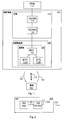
- FIG. 1 illustrates an example of a GSM/EDGE telecommunications system.
- GSM and EDGE stand for Global System for Mobile Communications and Enhanced Data rates for Global Evolution, respectively.
- the GSM/EDGE telecommunications system may be divided into an infrastructure (INFRA) 100 and a mobile station (MS) 102.
- IFRA infrastructure
- MS mobile station
- the infrastructure 100 includes a core network (CN) 104 and a GSM/EDGE radio access network (GERAN) 106.
- CN core network
- GERAN GSM/EDGE radio access network
- the GERAN 106 includes a base station system (BSS) 108, which includes a base station controller (BSC) 110 and base transceiver stations (BTS) 112A, 112B.
- BSS base station system
- BSC base station controller
- BTS base transceiver stations
- the base transceiver station 112A, 112B is referred to as a base station 112A, 112B.
- the mobile station 102 may also be referred to as user equipment, a mobile terminal, a subscriber terminal, a mobile telephone and a wireless game terminal.
- the MS 102 includes a memory for storing encoded instructions of computer processes.
- the computer processes may be executed in a digital signal processor of the MS 102.
- the CN 104 includes a serving GPRS support node (SGSN) 114, which is typically the centre point of the packet-switched domain of the CN 102.
- the main task of the SGSN 114 is to transmit packets to the mobile station 102 and receive packets from the mobile station 102 by using the GERAN 106.
- the SGSN 114 further contains subscriber and location information related to the mobile station 102.
- a gateway GPRS (General Packet Radio Service) support node (GGSN) 116 is a gateway between the CN 104 and a packet data network (PDN) 118.
- the PDN 118 includes the Internet, for example.
- the BSC 110 is responsible for the following tasks, for instance: radio resource management of the BTS 112A, 112B, inter-cell handovers, frequency control of the BTS 112A, 112B, management of frequency hopping sequences, time delay measurement on the uplink, implementation of the operation and maintenance interface, and power control.
- the BSC 110 includes a memory for storing encoded instructions of computer processes.
- the computer processes may be executed in a digital signal processor of the BSC 110.
- the BTS 112A, 112B comprises at least one transceiver which implements wireless communications channels 120 between the infrastructure 100 and the mobile station 102.
- the tasks the BTS performs 112A, 112B include, for example, calculation of timing advance (TA), uplink measurements, channel coding, encryption, decryption, frequency hopping, and managing GSM/EDGE protocols.
- TA timing advance
- the BTS 112A, 112B includes a memory for storing encoded instructions of computer processes.
- the computer processes may be executed in a digital signal processor of the BTS 112A, 112B.
- Figure 1 exemplifies a GSM/EDGE telecommunications system by means of packet-switched functionality, also referred to as E-GPRS (Enhanced GPRS), and the corresponding network elements.
- E-GPRS Enhanced GPRS
- the GSM/EDGE telecommunications system includes circuit-switched domain, which supports ECSD (Enhanced Circuit Switched Data) functionality.
- ECSD Enhanced Circuit Switched Data
- the SGSN 114 and the GGSN 116 represent second generation (2G) network elements of the CN 104.
- the CN 104 may further include third generation (3G) network elements, which may be connected to the 2G network elements and to the GERAN 106.
- FIG. 2 shows an example of the structure of a mobile station 200 by means of a block diagram.
- the mobile station 200 comprises a digital signal source (DSS) 202, a wide-band carrier wave generator (WCWG) 206 and an antenna 208.
- DSS digital signal source
- WWG wide-band carrier wave generator
- the DSS 202 generates a digital signal 204 and feeds the digital signal 204 into the WCWG 206.
- the digital signal 204 may carry payload, signalling information and/or training sequences. The information content, however, is not a critical issue for the present solution, and the digital signal may carry any information that may be presented in a digital form.
- the WCWG 206 receives the digital signal 204, generates a wide-band carrier wave 210 by modulating the digital signal 204 with linear modulation, and transmits the wide-band carrier wave 210 over an air interface via the antenna 208.
- the DSS 202 may perform tasks such as fetching a data stream from a data stream source, such as a memory, camera, and speech codec, providing source coding for the data stream, implementing a channel coding and/or interleaving on the data stream, and multiplexing the data stream according to an applied multiplexing method.
- a data stream source such as a memory, camera, and speech codec
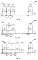
- Figure 3A shows the carrier wave structure according to the prior art
- Figures 3B and 3C illustrate the carrier wave structure according to embodiments of the invention.
- the x-axis 302 and y-axis 304 show frequency and signal power, respectively, in arbitrary units.
- Figure 3A shows a group of carrier waves 300A comprising narrow-band carrier waves 306A, 306B, 306C, 306D.
- narrow band refers to a narrow bandwidth 312 obtained with the conventional modulation symbol rate, also referred to as a first modulation symbol rate.
- the narrow-band carrier waves 306A-306D are separated by a predefined carrier spacing 310, which is typically defined as a separation of the band origins 308A, 308B, 308C, 308D of the narrow-band carrier waves 306A-306D.
- the predefined carrier spacing 310 is 200 kHz.
- a wide-band carrier 314 is generated into the group of the carrier waves 300B by applying linear modulation at a second modulation symbol rate that is a multiple of the first modulation symbol rate applied to the narrow-band carrier waves 306A-306D.
- the narrow-band carrier wave 306B is replaced with the wide-band carrier wave 314 while the structure of the rest of the group of the carrier waves 300A remains unaltered.
- the predefined carrier spacing 310 is preserved and the wide-band carrier wave 314 is allowed to overlap with adjacent carrier waves 306A, 306C.
- the second modulation symbol rate is twice the first modulation symbol rate.
- the first modulation symbol rate is 13/48 MHz
- the second modulation symbol rate of 26/48 MHz is obtained.
- the linear modulation at the second modulation symbol rate results in a wide bandwidth 316 of the wide-band carrier wave 314.
- the second modulation symbol rate of 26/48 MHz results in the wide bandwidth 316 of about 600 kHz.
- the group of carrier waves 300C includes wide-band carrier waves 318A, 318B, 318C.
- the location of the band origins 308B, 308C, 308E and the carrier spacing 310 of the wide-band carrier waves 318A, 318B, 318C are preserved with respect to the case where the group of carrier waves 300A, 300B includes narrow-band carrier waves 306A-306C.
- the burst structure of the GSM/EDGE burst is preserved in the conventional structure, i.e. in the structure applied when transmitting signals at the first symbol rate.
- the length of the training sequences is extended from 26 to 52, where 26 and 52 correspond to the first modulation symbol rate and the second modulation symbol rate, respectively.
- the wide-band carrier wave generator 400 typically includes an I-modulator 404A and a Q-modulator 404B.
- the digital signal 402 is converted from a serial format into a parallel format in a serial-to-parallel converter (S/P) 426, and parallel components of the digital signal 402 are fed into the I-modulator 404A and the Q-modulator 404B.
- S/P serial-to-parallel converter
- the I-modulator 404A is provided with a first analog signal waveform 424A which encodes the bits of the digital signal 402 according to the applied linear modulation at the second modulation symbol rate.
- the Q-modulator 404B is provided with a second analog signal waveform 424B which encodes the bits of the digital signal 402 according to the applied linear modulation at the second modulation symbol rate.
- the first analog waveform 424A and the second analog waveform 424B may be generated in a frequency generator (FG) 406 which adjusts signal characteristics of the first analog waveform 424A and those of the second analog waveform 424B so that the applied modulation is realized.
- FG frequency generator
- Such signal characteristics may be the relative phase and/or amplitude of the first analog waveform 424A and the second analog waveform 424B.
- the frequency generator 406 may be provided with a control signal 414 including, for example, instructions on the applied modulation scheme and a clock signal.
- the timing information carried by the clock signal may be used to synchronize the feeding of the digital signal 402 into the wide-band carrier wave generator 400.
- the I-modulator 404A outputs an I-branch waveform 408A into a combiner 410.
- the Q-modulator 404B outputs a Q-branch waveform 408B into the combiner 410.
- the combiner 410 combines the I-branch waveform 408A and the Q-branch waveform 408B and outputs a combined waveform 412.
- the I-modulator 404A and the Q-modulator 404B may be implemented with a digital signal processor and software. In some applications, the I-modulator 404A and the Q-modulator 404B are implemented with ASICs (Application-Specific Integrated Circuit).
- ASICs Application-Specific Integrated Circuit
- the combined waveform 412 is fed into an up-converter 416 which converts the combined waveform 412 into the wide-band carrier wave 422.
- the up-converter 416 is typically coupled to a local oscillator 420 which provides a local oscillator frequency 418 for the up-converter 416.
- M-PSK M-ary phase shift keying
- 8-PSK octal phase shift keying
- M-QAM M-ary quadrature amplitude modulation
- the tail bits, training sequence bits, and the data bits are encoded at the M-ary modulation rate.
- the wide-band carrier wave generator 400 is further capable of implementing narrow-band carrier waves 306A-306D.
- a network element (NE) 500 of the infrastructure 100 includes at least two diversity antennas 504A, 504B for sampling an electromagnetic field associated with the wide-band carrier wave 512 transmitted from the mobile station 102.
- the diversity antennas 504A, 504B are coupled to a wide-band carrier receiver (WCR) 502 which receives and demodulates the wide-band carrier wave 512 at the second symbol rate.
- WCR 502 may include receive antenna branches 506A, 506B, each coupled to an individual diversity antenna 504A, 504B.
- Each receive antenna branch 506A, 506B demodulates the wide-band carrier wave 512 separately, and outputs a receive antenna branch-specific digital signal 508A, 508B.
- the receive antenna branch-specific digital signals 508A, 508B are inputted into a base band domain (BBD) 510 of the network element 500 for further processing.
- BBD 510 outputs processed signals 514 to the higher layers of the GSM/EDGE telecommunications system.
- the network element 500 is a base station 112A, 112B.
- the network element 500 utilizes an interference rejection combining (IRC) algorithm in the uplink reception.
- the IRC algorithm may be directed at the receive antenna branch-specific digital signals 508A, 508B and implemented with a digital signal processor and software in the base band domain 510 of the network element 500.
- IRC algorithms provide a well-known solution for reducing interference caused by overlapping carrier waves, such as the wide-band carrier waves 318A-318C shown in Figure 3C. It is assumed that a person skilled in the art is capable of implementing IRC algorithms in GSM/EDGE telecommunications systems without further description.
- the receive antenna branch 600 typically includes a down-converter 604, an I-demodulator 610A, a Q-demodulator 610B, a frequency generator 626 and a combiner 616.
- the wide-band carrier wave 602 received by the diversity antenna 504A, 504B is inputted into the down-converter 604 which down-converts the wide-band carrier wave 602 into a low-frequency waveform 608.
- the down-converter 604 is provided with a local oscillator frequency 620 for the downconversion.
- the local oscillator frequency 620 may be generated in a local oscillator 606.
- the low-frequency waveform 608 is inputted into the I-demodulator 610A which demodulates the low-frequency waveform 608 and outputs an I-demodulated signal 614A.
- the low-frequency waveform 608 is further inputted into the Q-demodulator 610B which demodulates the low-frequency waveform 608 and outputs a Q- demodulated signal 614B.
- the I-demodulated signal 614A and the Q-demodulated 610B signal are fed into the combiner 616 which combines the I-demodulated signal 614A and the Q-demodulated 610B signal and outputs a combined digital signal 618.
- the I-demodulator 610A and the Q-demodulator 610B are provided with an I-signal waveform 612A and a Q-signal waveform 612B, respectively.
- the I-signal waveform 612A and the Q-signal waveform 612B may be generated in the frequency generator (FG) 626 which adjusts signal characteristics of the I-signal waveform 612A and those of the Q-signal waveform 612B so that the applied modulation is realized.
- Such signal characteristics may be the relative phase and/or amplitude of the I-signal waveform 612A and those of the Q-signal waveform 612B.
- the I-demodulator 610A and the Q-demodulator 610B may be implemented with a digital signal processor and software. In some applications, the I-demodulator 610A and the Q-demodulator 610B are implemented with ASICs (Application-Specific Integrated Circuit).
- ASICs Application-Specific Integrated Circuit
- the frequency generator 626 may be provided with a control signal 622 including, for example, instructions on the applied modulation scheme and a clock signal.
- the mobile station 102 may in some embodiments signal capability information 122 to the infrastructure 100 about the capability of the mobile station 102 to apply the second modulation symbol rate.
- the capability information may include, for example, a list of modulation methods and modulation symbol rates supported by the mobile station 102.
- the capability information 122 may be signalled by using higher layer signalling and associated signalling channels.
- the signalling associated with the capability information is received in the base station 112A, 112B and possibly delivered to higher layers, such as the base station controller 110 of the GERAN 106.
- the infrastructure 100 of the GSM/EDGE telecommunications system controls whether or not to apply the second modulation symbol rate in the mobile station 102.
- the decision whether to apply the second modulation symbol rate may be based on the capability information 122 received from the mobile station 102, the prevailing interference situation in the GSM/EDGE system, and the service being provided.
- Control information 124 about the modulation symbol rate to be applied in the mobile station 102 may be generated in the base station 112A, 112B and/or in the base station controller 110 and signalled to the mobile station 102.
- the mobile station 102 receives the control information 124 and the wide-band carrier wave generator 206 applies a modulation symbol rate according to the control information 124 provided by the infrastructure 100 of the GSM/EDGE telecommunications system.
- the IRC algorithm is utilized in the uplink reception.
- capability information 122 about the capability of the mobile station 102 to apply the second modulation symbol rate is signalled from the mobile station.
- At least one wide-band carrier wave 314, 318A, 318B, 318C is generated in the mobile station 102 in the group of carrier waves 300B, 300C by applying linear modulation at a second modulation symbol rate, the second modulation symbol rate being a multiple of the first modulation symbol rate, while preserving the predefined carrier spacing 310 and allowing the at least one wide-band carrier wave 314, 318A-318C to overlap with at least one adjacent carrier wave.
- the invention provides a computer program embodied on a distribution medium.
- the computer program includes encoded instructions for executing a computer process in a GSM/EDGE telecommunications system.
- the computer process is described in conjunction with Figure 7.
- the computer process may be executed by using a digital signal processor and software. Whether to execute each process step in the mobile station 102, base station 112A, 112B or base station controller 110 is clear from the above description.
- the distribution medium may comprise a computer readable medium, a program storage medium, a record medium, a computer readable memory, a computer readable software distribution package, a computer readable signal, a computer readable telecommunications signal, and a computer readable compressed software package.
Landscapes
- Engineering & Computer Science (AREA)
- Signal Processing (AREA)
- Computer Networks & Wireless Communication (AREA)
- Mobile Radio Communication Systems (AREA)
Applications Claiming Priority (1)
| Application Number | Priority Date | Filing Date | Title |
|---|---|---|---|
| FI20055001A FI20055001A0 (fi) | 2005-01-03 | 2005-01-03 | Ylälinkin tiedonsiirto GSM/EDGE-järjestelmässä |
Publications (1)
| Publication Number | Publication Date |
|---|---|
| EP1677451A2 true EP1677451A2 (de) | 2006-07-05 |
Family
ID=34112652
Family Applications (1)
| Application Number | Title | Priority Date | Filing Date |
|---|---|---|---|
| EP05112735A Withdrawn EP1677451A2 (de) | 2005-01-03 | 2005-12-22 | Vermittlung in der Aufwärtsrichtung in einem GSM/EDGE-System |
Country Status (4)
| Country | Link |
|---|---|
| US (1) | US7672642B2 (de) |
| EP (1) | EP1677451A2 (de) |
| FI (1) | FI20055001A0 (de) |
| WO (1) | WO2006072662A1 (de) |
Families Citing this family (7)
| Publication number | Priority date | Publication date | Assignee | Title |
|---|---|---|---|---|
| US20080037411A1 (en) * | 2004-05-14 | 2008-02-14 | Nokia Corporation | Variable filtering for radio evolution |
| US7957351B2 (en) * | 2005-04-04 | 2011-06-07 | Qualcomm Incorporated | Method and apparatus for management of multi-carrier communications in a wireless communication system |
| FI20055687A0 (fi) | 2005-12-21 | 2005-12-21 | Nokia Corp | Radiokanavajako ja siirtoyhteyden sovitus solukkojärjestelmässä |
| US20080014877A1 (en) * | 2006-04-19 | 2008-01-17 | Nokia Corporation | Carrier frequency shifting in mobile communications |
| US7808964B2 (en) * | 2006-04-19 | 2010-10-05 | Nokia Corporation | Modified dual symbol rate for uplink mobile communications |
| US9887764B1 (en) * | 2015-04-07 | 2018-02-06 | Syed Karim | Systems for harvesting, storing, and sharing data files |
| EP3637877B1 (de) * | 2017-08-09 | 2023-04-12 | Guangdong Oppo Mobile Telecommunications Corp., Ltd. | Uplink-übertragungsverfahren und -endgerät |
Family Cites Families (9)
| Publication number | Priority date | Publication date | Assignee | Title |
|---|---|---|---|---|
| US5878037A (en) * | 1996-12-18 | 1999-03-02 | Lucent Technologies Inc. | Code division switching scheme |
| US6456627B1 (en) * | 1997-08-29 | 2002-09-24 | Telefonaktiebolaget Lm Ericsson (Publ) | Method for communicating information in a communication system that supports multiple modulation schemes |
| FI106233B (fi) | 1997-12-11 | 2000-12-15 | Nokia Networks Oy | Tiedonsiirtomenetelmä ja lähetin |
| US6891887B1 (en) * | 1998-05-27 | 2005-05-10 | 3Com Corporation | Multi-carrier LAN adapter device using interpolative equalizer |
| US6711214B1 (en) * | 2000-04-07 | 2004-03-23 | Adc Broadband Wireless Group, Inc. | Reduced bandwidth transmitter method and apparatus |
| JP3550085B2 (ja) | 2000-11-01 | 2004-08-04 | 松下電器産業株式会社 | 無線送信装置および無線送信方法 |
| FR2820564B1 (fr) * | 2001-02-02 | 2003-04-18 | Nortel Networks Ltd | Dispositifs d'emission et de reception de signal module |
| US6891841B2 (en) * | 2001-03-12 | 2005-05-10 | Advent Networks, Inc. | Time division multiple access over broadband modulation method and apparatus |
| CA2704041C (en) * | 2001-03-30 | 2013-09-03 | M&Fc Holding, Llc | Enhanced wireless packet data communication system, method, and apparatus applicable to both wide area networks and local area networks |
-
2005
- 2005-01-03 FI FI20055001A patent/FI20055001A0/fi not_active Application Discontinuation
- 2005-12-21 US US11/312,492 patent/US7672642B2/en not_active Expired - Fee Related
- 2005-12-22 EP EP05112735A patent/EP1677451A2/de not_active Withdrawn
-
2006
- 2006-01-02 WO PCT/FI2006/050001 patent/WO2006072662A1/en not_active Ceased
Also Published As
| Publication number | Publication date |
|---|---|
| FI20055001A0 (fi) | 2005-01-03 |
| US20060160553A1 (en) | 2006-07-20 |
| US7672642B2 (en) | 2010-03-02 |
| WO2006072662A1 (en) | 2006-07-13 |
Similar Documents
| Publication | Publication Date | Title |
|---|---|---|
| US10014910B2 (en) | Method for distributed mobile communications, corresponding system and computer program product | |
| CN105979588B (zh) | 用于无线通信的高效前传通信的系统和方法 | |
| US20080168199A1 (en) | Dynamic readjustment of power | |
| JPH1117644A (ja) | 無線基地局、無線端末、無線通信システムおよびそのキャリア割り当て制御方法 | |
| WO2007017807A1 (en) | A multicarrier modulation with enhanced frequency coding | |
| JP2000511721A (ja) | 高データ速度cdma無線通信システム | |
| KR100572577B1 (ko) | 직교 주파수 분할 다중 통신 시스템 및 방법 | |
| EP2090051B1 (de) | Verfahren und vorrichtung zum erzeugen von datenpaketen zur übertragung in einem ofdm-kommunikationssystem | |
| CN1679288A (zh) | 在无线通信网络中利用开销数据进行训练 | |
| US20080037411A1 (en) | Variable filtering for radio evolution | |
| EP1677451A2 (de) | Vermittlung in der Aufwärtsrichtung in einem GSM/EDGE-System | |
| EP1145573B1 (de) | Kommunikationssystem mit reduzierter leistungsvariation und verfahren dafür | |
| JP2001274768A (ja) | 通信装置及び通信方法 | |
| JP4619797B2 (ja) | 無線通信システム及び無線通信装置 | |
| US9596663B2 (en) | Method and apparatus for transmitting and receiving training sequence code in communication system | |
| JP2009118388A (ja) | 受信装置 | |
| JPH1188941A (ja) | 移動通信のチャネル構成方法および移動通信システム | |
| US7808964B2 (en) | Modified dual symbol rate for uplink mobile communications | |
| JP5166828B2 (ja) | Ipデータ無線通信システム | |
| KR100758333B1 (ko) | 무선 통신 시스템을 위한 모뎀, 이를 이용한 송신 장치 및그의 송신 전력 제어 방법 | |
| EP2057743B1 (de) | Variable filterung für funkbeurteilung | |
| CN101151767B (zh) | 天线自适应方法、通信终端、设备和模块 | |
| US20040252663A1 (en) | Cdma transmission diversity apparatus | |
| CN121750109A (zh) | 太赫兹频段无线通信系统 | |
| JP2006060572A (ja) | 送信装置,受信装置,および通信システム |
Legal Events
| Date | Code | Title | Description |
|---|---|---|---|
| PUAI | Public reference made under article 153(3) epc to a published international application that has entered the european phase |
Free format text: ORIGINAL CODE: 0009012 |
|
| AK | Designated contracting states |
Kind code of ref document: A2 Designated state(s): AT BE BG CH CY CZ DE DK EE ES FI FR GB GR HU IE IS IT LI LT LU LV MC NL PL PT RO SE SI SK TR |
|
| AX | Request for extension of the european patent |
Extension state: AL BA HR MK YU |
|
| STAA | Information on the status of an ep patent application or granted ep patent |
Free format text: STATUS: THE APPLICATION IS DEEMED TO BE WITHDRAWN |
|
| 18D | Application deemed to be withdrawn |
Effective date: 20110704 |