EP1677253A1 - Method and device of reconstructing an (n+1)-dimensional image function from radon data - Google Patents
Method and device of reconstructing an (n+1)-dimensional image function from radon data Download PDFInfo
- Publication number
- EP1677253A1 EP1677253A1 EP04031043A EP04031043A EP1677253A1 EP 1677253 A1 EP1677253 A1 EP 1677253A1 EP 04031043 A EP04031043 A EP 04031043A EP 04031043 A EP04031043 A EP 04031043A EP 1677253 A1 EP1677253 A1 EP 1677253A1
- Authority
- EP
- European Patent Office
- Prior art keywords
- projection
- imaging device
- imaging
- source
- energy input
- Prior art date
- Legal status (The legal status is an assumption and is not a legal conclusion. Google has not performed a legal analysis and makes no representation as to the accuracy of the status listed.)
- Withdrawn
Links
Images


Classifications
-
- G—PHYSICS
- G06—COMPUTING; CALCULATING OR COUNTING
- G06T—IMAGE DATA PROCESSING OR GENERATION, IN GENERAL
- G06T11/00—2D [Two Dimensional] image generation
-
- A—HUMAN NECESSITIES
- A61—MEDICAL OR VETERINARY SCIENCE; HYGIENE
- A61B—DIAGNOSIS; SURGERY; IDENTIFICATION
- A61B6/00—Apparatus for radiation diagnosis, e.g. combined with radiation therapy equipment
- A61B6/02—Devices for diagnosis sequentially in different planes; Stereoscopic radiation diagnosis
- A61B6/03—Computerised tomographs
- A61B6/032—Transmission computed tomography [CT]
-
- A—HUMAN NECESSITIES
- A61—MEDICAL OR VETERINARY SCIENCE; HYGIENE
- A61B—DIAGNOSIS; SURGERY; IDENTIFICATION
- A61B6/00—Apparatus for radiation diagnosis, e.g. combined with radiation therapy equipment
- A61B6/48—Diagnostic techniques
- A61B6/482—Diagnostic techniques involving multiple energy imaging
-
- G—PHYSICS
- G06—COMPUTING; CALCULATING OR COUNTING
- G06T—IMAGE DATA PROCESSING OR GENERATION, IN GENERAL
- G06T11/00—2D [Two Dimensional] image generation
- G06T11/003—Reconstruction from projections, e.g. tomography
- G06T11/006—Inverse problem, transformation from projection-space into object-space, e.g. transform methods, back-projection, algebraic methods
-
- A—HUMAN NECESSITIES
- A61—MEDICAL OR VETERINARY SCIENCE; HYGIENE
- A61B—DIAGNOSIS; SURGERY; IDENTIFICATION
- A61B6/00—Apparatus for radiation diagnosis, e.g. combined with radiation therapy equipment
- A61B6/02—Devices for diagnosis sequentially in different planes; Stereoscopic radiation diagnosis
- A61B6/027—Devices for diagnosis sequentially in different planes; Stereoscopic radiation diagnosis characterised by the use of a particular data acquisition trajectory, e.g. helical or spiral
-
- A—HUMAN NECESSITIES
- A61—MEDICAL OR VETERINARY SCIENCE; HYGIENE
- A61B—DIAGNOSIS; SURGERY; IDENTIFICATION
- A61B6/00—Apparatus for radiation diagnosis, e.g. combined with radiation therapy equipment
- A61B6/06—Diaphragms
-
- G—PHYSICS
- G06—COMPUTING; CALCULATING OR COUNTING
- G06T—IMAGE DATA PROCESSING OR GENERATION, IN GENERAL
- G06T2211/00—Image generation
- G06T2211/40—Computed tomography
- G06T2211/416—Exact reconstruction
Definitions
- the present invention relates to a method of reconstructing an (n+1)-dimensional image function from n-dimensional or less dimensional Radon data comprising a plurality of projection functions measured corresponding to a plurality of predetermined projection directions. Furthermore, the present invention relates to a method and a device for imaging a region of investigation on the basis of the above reconstructing method.
- the iterative reconstruction is an approximation method based on a plurality of iteration steps. Each point in a projection corresponds to a line in the reconstructed image. The projections are thus back-projected. This leads as a first step to a very crude approximation. Subsequently, the imaging process of transforming the Radon data is simulated for this approximation and then differences are calculated to do a back-projection again. For an optimization of the reconstructed picture, this iteration is repeated many times.
- the essential disadvantage of the iterative reconstruction is that the above iteration leads to extremely long calculation times.
- the filtered back-projection method relies in principle on the Fourier-slice theorem describing a relationship of the Fourier transform of the Radon data and Fourier transformed image data.
- a general disadvantage of using the Fourier-slice theorem lies in the fact that an interpolation step in the reconstruction results in errors and artifacts which have a tendency even to increase with increasing space frequency.
- the capability of reconstructing images with fine details is limited. This disadvantage could be avoided by using detectors with high resolution only. However, the application of these detectors is limited in terms of dose burden, costs and data processing time.
- Another problem is related to the discretization of the Radon data from which the image data have to be reconstructed.
- the so-called Feldkamp algorithm or the advanced single slice reconstruction are methods that try to adapt the filtered back-projection algorithm to the case where the data are collected in helical computed tomography with fan or cone beam geometry which results in data points not evenly spread within the z-axis direction and the rays along which the projection and integrations take place are tilted against each other.
- the Fourier-slice theorem all possible rays have to be evaluated, because otherwise the error for high space frequencies would be larger. This leads to further uncertainties and unsharpness.
- the conventional techniques allow that the unsharpness of the structure reconstruction can be reduced, but not avoided, by using algorithms with a higher need of computational power.
- the objective of the invention is to provide improved methods of reconstructing image functions from Radon data, leading to an increased range of applications in non-destructive investigations and avoiding the disadvantages of the conventional reconstructing techniques.
- the objective of the invention is to provide reconstruction methods yielding image functions with reduced unsharpriess and reduced artifacts even at high space frequencies.
- a further aspect of the objective of the invention is to provide an improved imaging method avoiding the disadvantages of the conventional imaging methods based on the collection of Radon data.
- Another objective of the invention is to provide improved devices for imaging a region of investigation by reconstructing measured Radon data.
- the objective of the invention is to provide an imaging device which allows a reduction of an amount of energy input( e. g. radiation dose) and scattering effects within the region of investigation.
- an (n+1)-dimensional image function f representing a region of investigation is determined from n-dimensional or less dimensional Radon data as a sum of polynomials multiplied with values of projection functions p ⁇ (t) measured corresponding to a plurality of predetermined projection directions ( ⁇ ) through the ROI.
- the present invention provides the image function f as an approximation of polynomial functions.
- the inventors have found that this approximation is determined just by the projection functions coming from the Radon data.
- the image function can be calculated using much less computational time than normally used by iterative reconstruction and comparable at least to that used by filtered back-projection algorithms.
- the invention allows a fast reconstruction with very few artifacts and with resolution and noise properties directly combined to the number of measured energy quanta or the strength of the measured projection signals. Additionally the reconstruction does not use any interpolation.
- the (n+1)-dimensional image reconstructed according to the invention does not suffer from resolution decrease due to the reconstruction itself and has less artifacts introduced by the reconstruction.
- the subject of the invention is a method of reconstructing the image function ⁇ as such.
- the image function f is a representation of the region of investigation (ROI).
- the values of the image function are determined by the local parameters or features of the ROI.
- the dimension of the image function depends on the dimension of the ROI, in particular on the number of parameters necessary for completely describing each point in the ROI.
- the image function has (n+1) dimensions (n: natural number, n ⁇ 1).
- the term "image function" used herein does not necessarily refer to a visualized picture, but rather to a representation of the features of the real ROI or parts thereof, wherein the representation may be e.g. a numerical representation, a graphical representation or the like.
- the "image function" represents an approximation whose quality depends on the amount of data processed, but not on any interpolation.
- the approximation of the image function on a circle-shaped unit disc extending in the region of investigation is described in the following.
- the approximation on an ellipse-shaped disc can be done in an analogue way as outlined below.
- ROI region of investigation
- the term "region of investigation” (ROI) used herein generally refers to an object under investigation or a part thereof.
- the ROI can be described as a 2- or higher dimensional entity as described above with reference to the image function.
- the ROI can be described by a smooth, continuous function without discontinuities like e.g. steps. It is an important advantage of the invention, however, that this condition of reconstructing a smooth ROI is fulfilled in all practical applications of the invention. Even a crack in a material under investigation does not represent an ideal discontinuity but rather a blurred step which can be reconstructed with the method of the invention.
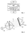
- projection direction used herein generally refers to the linear course of an energy input through the ROI in the (n+1)-dimensional space. In the 2- or 3-dimensional case, the projection direction can be defined by angles relative to a coordinate system used. If fan or cone beams are considered, the term “main projection direction” indicates the orientation of the central beam component in the fan or cone beam.
- the Radon data measured at the ROI comprise a set of projection functions which have been determined corresponding to a plurality of predetermined projection directions running through the ROI.
- the n-dimensional data are collected with a certain number, which might in theory be infinite large, of "projections”. These projections are characterized by integrating the interesting effect over one-dimensional lines. By measuring a sufficient number of these integrated "projections", important features of the object can be reconstructed from the Radon data.
- the values of the projection functions generally are determined by the interaction (in particular attenuation, e.g. by absorption, scattering or reflection) of an energy input beam travelling through the ROI along the respective projection direction. While the projection function is a one-dimensional function, the entirety of projection functions corresponding to all available projection directions spans a space (Radon space) of higher dimensions. Generally, for reconstructing the (n+1)-dimensional image function, Radon data with n-dimensions are required. However, the reconstruction with Radon data having less dimensions is also possible.
- energy input beam refers to all types of a physical quantity, which travels along a straight line (or an essentially straight line) through the ROI while the energy carried is changed due to an interaction with the ROI.
- energy input beam covers electromagnetic radiation, particle radiation, sound waves or electrical current.
- Radon data refers not only to the data obtained by the above projections through the ROI, but also to data obtained by measuring an energy output obtained by reflection within the object investigated. These Radon data (or: Radon-like data) are obtained e.g. with the investigation of objects by the use of ultrasound waves. It is an essential advantage of the invention that the reconstruction of the image function can be implemented for Radon-like data.
- the image function f has two, three or four dimensions with n being selected from 1, 2 or 3.
- the reconstruction of a 2-dimensional image function f has the particular advantage in that the multiplication of the polynomials with values of the projection functions can be done with low computational power.
- the 2-dimensional image function represents e.g. an image of a disc section in an object under investigation.
- the reconstruction of a 3-dimensional image function has an advantage in that the calculation for reconstructing the image function can be obtained by a simple adaptation of the 2-dimensional case.
- the invention-based calculation for the 2D and the 3D case are based on mathematical operations which can be implemented in a very simple way, and with the possibility of precalculating a lot of values and store them within a computer or another data carrier, like e.g. a memory chip or chips. This means the number of operations will be greatly reduced as matrix elements (see equation 2.3 in section 3) can be precalculated.
- the invention can be adapted with advantage to the 4-dimensional case wherein the ROI comprises three dimensions in space and time as the fourth dimension.
- the 4-dimensional image function is represented by a time sequence of a three-dimensional representation of an object under investigation e.g. a running motor engine, or an organ of a living organism, e.g. the heart.
- the invention offers essentially new applications of non-destructive imaging, e.g. with computer tomography.
- the high accuracy of reconstruction by the invention allows the reduction of energy input, e.g. X-rays which leads to a computing time reduction. Due to this computing time reduction obtained with invention, processes with relative high frequencies, e.g. the function of the beating heart, can be investigated in real time by an online imaging process.
- the image function f is determined on the basis of sums of orthogonal ridge polynomials.
- a measurement of projection functions is always associated with a discretization in practice. Due to the discretization of e.g. radiation sensor elements, any projection functions measured are composed of attenuation values according to single rays of energy or particle radiation. On the one hand, this discretization is advantageous for the sum calculation according to the invention. Furthermore, the method of the invention can be applied for reconstructing raw data obtained with conventional devices e.g. CT devices. On the other hand, the reconstruction method of the invention allows to achieve the above objective by using only certain discrete rays along which the integrated projection takes place. This is possible as the image function on a compact set can be approximated by the polynomials. The reconstructed image function is even an exact replica if the ROI is represented by a polynomial of degree less than the number of projection directions. The basic idea behind this is that continuous functions can be approximated accurately by polynomials.
- the projection functions p ⁇ (t) comprise discrete projection profiles, wherein each discrete projection profile comprises projection values ⁇ (v,j) corresponding to a plurality of projection lines (j) with the same projection direction (v).
- the number and geometric features of the integrated projections for reconstructing the object properties to be investigated is selected in dependence on the particular application.
- the selection of the number and distances of the projection lines and the projection directions is done in dependence on the spatial resolution to be obtained, as an example by way of test measurements.
- the polynomials used for reconstructing the image function are expressed with integrals on the ROI, e.g. on a disc section of ROI.
- the integrals can be calculated numerically as known in the art.
- the integrals in the definition of the polynomials are discretized by a quadrature sum I .
- the quadrature sum I represents a discrete approximation of the integrals as outlined in the discussion of the mathematical background (see section 3.).
- the implementation of quadrature sums facilitates a direct processing of the measured data without any intermediate adjustment steps.
- the discretization of the integrals by the Gaussian quadrature sum which has the important advantage in that the approximation of the integrals is more precise as a larger amount of polynomials is preserved despite of the discretization.
- a feature of the reconstruction method is that the discrete projection values obtained with the same projection direction are measured such that the circumference of the unit disc in the ROI is divided by the projection lines into equal arc lengths.
- a polynomial matrix T can be constructed, the elements of which are sums of polynomials (see section 3).
- the image function is approximated as a sum A of the discrete projection values multiplied by the corresponding elements of the polynomial matrix T added for all projections directions:
- the essential advantage of this embodiment consists in that the image function reconstruction is reduced to a simple double sum calculation which allows a reduction of calculation time.
- the number of calculations and its type allows fast evaluation of the above mentioned double sum due to the fact that no interpolation and re-binning is needed and a lot of calculations can be done beforehand, because the matrix used is in general only depending on the geometric conditions of the data collection. This means it can be precalculated and stored within the reconstruction computer or another data carrier.
- the polynomial matrix T allows an adaptation to particular conditions of measuring the projection values.
- the inventors have found that the conditions of measuring the projection functions directly influence the elements of the polynomial matrix.
- a system calibration due to non-homogenous radiation of the tube or non-linear response of the detector elements can be used as calibration properties and put into the polynomial matrix T to improve the image quality by online calibration.
- the improvement comes from the fact that various interpolations for conventional reconstruction schemes are no longer needed. Therefore, with a preferred feature of the invention, a calibration of the polynomial matrix T is introduced for providing an adjusted polynomial matrix T* . As long as the conditions of measurement are not amended, the adjusted polynomial matrix T* can be used for reconstructing the image function of different objects.
- At least one of an energy distribution function of an energy generator device, a sensitivity distribution function of a detector device used for measuring the projection functions, and a scattering function of the object is used for constructing a calibration matrix ⁇ .
- the adjusted polynomial matrix T * can be obtained from the polynomial matrix simply by multiplication by the calibration matrix.
- a calibration measurement can be implemented e.g. in CT devices with a homogenous sphere made of PMMA for measuring the energy distribution of the X-ray source (Heel-effect) and the sensitivity distribution of the sensor elements.
- the theoretical estimation of the scattering function as it is known from conventional techniques can be used for calibration.
- a strong disturbance due to scattering can be avoided by the invention if the projections are measured with straight pencil or needle beams having a reduced scattering effect (see below).
- the polynomial matrix T used for approximating the image function has an essential advantage in that the elements of the polynomial matrix depend on measurement geometry only.
- the elements of the polynomial matrix T depend on the number and distances of the projection lines and the election of projection directions only. Therefore, the polynomial matrix needs to be calculated one time only for a predetermined set of geometric measurement conditions.
- the adjusted polynomial matrix T * which can be used for multiple measurements as long as the measurement conditions as e.g. the energy or the sensitivity distributions are not changed.
- At least one of the polynomial matrix T and the calibrated polynomial matrix T * is stored in a storage connected with or contained in a measuring device for measuring the projection functions.
- a storage connected with or contained in a measuring device for measuring the projection functions.
- the reconstruction method is connected with the measurement of the projection functions, wherein the process of measuring the projection functions firstly comprises the step of arranging an object to be investigated in the measuring device for adjusting the geometrical conditions of the measurement. Subsequently, the object is subjected to an energy input directed along the plurality of predetermined projection directions ( ⁇ ). For each of the energy inputs, the projection functions p ⁇ (t) are measured.
- the combination of the measurement with the reconstruction as provided by this embodiment represents an essential development compared to conventional techniques. Due to the high reconstruction speed, the image function can be determined immediately after the measurement along a full circle of projection directions. The measurement of the data and the arrangement of the object in the measuring device can be optimized during the scanning to achieve better result.
- helical projection data can be processed for obtaining 2- or 3- dimensional image functions.
- the inventors have found that the conventional algorithms for adapting a reconstruction method to measurements with inclined disc sections can be applied to the reconstruction method of the invention.
- at least one of the object and the measuring device is translated in a predetermined direction, e.g. perpendicular to the projection directions ( ⁇ ) during the step of subjecting the object to the energy input for obtaining the helical projection data.
- the sum of polynomials is subjected to a predetermined multiplier function which reduces the contributions of polynomials of higher degrees according to the multiplier function.
- this multiplier function allows a reduction of artifacts and improves the approximation of the image function.
- the multiplier function has the effect of a filter with a smooth transfer function filtering polynomials of the higher degrees in the orthogonal basis considered. In contrast to conventional techniques, this filter is not a traditional filter in the Fourier domain.
- the invention can be used for reconstructing (n+1)-dimensional data from Radon data or Radon-like data in n or less dimensions. It is an essential advantage of the invention, that this reconstruction can be used in various applications like many applications in medical imaging, for example CT, PET, SPECT, gamma-camera imaging etc.. However, there are a lot more possible applications like ultrasound tomographic imaging, light tomography, any multidimensional imaging for industrial testing or biological research and so on.
- the image function f is determined from Radon data measured in an X-ray computer tomography (CT) device, an ultrasound tomography device, a PET imaging device, a Gamma-ray imaging device, a SPECT imaging device, a neutron based transmission detection system, or an electrical impedance tomography device.
- CT computer tomography
- an imaging method for imaging the ROI wherein a plurality of straight energy input beams is directed at predetermined projection directions through the ROI and associated projection functions p ⁇ (t) are determined comprising attenuation values measured along the projection directions.
- the projection functions p ⁇ (t) are subjected to a reconstructing method according to the above first aspect of the invention.
- the imaging method of the present invention allows the direct processing of the measured projection data without re-binning.
- the image function can be calculated directly from the raw data obtained with an imaging device.
- an approximation of the image function is represented as a visualized image, e.g. with at least one 2- or 3-dimensional picture or a corresponding video representation (motion picture).
- the image function can be subjected to further image processing, e.g. for automatically detecting predetermined features.
- prior art image processing methods can be applied on the image function determined according to the invention.
- the provision of the visualized image comprises the step of calculating visualizations of the object, e.g. by converting the values of the image function into grey values.
- the imaging method of the invention can be applied for any collection of Radon data obtained from any type of energy input acted on the object.
- the imaging method can be implemented with many types of radiation sources that generate electromagnetic or particle radiation with a certain distribution.
- the energy input beams are fan beams or cone beams.
- the irradiation of the ROI with a radiation source having a fan or cone beam characteristic has the particular advantage in that conventional imaging devices, like e.g. CT or SPECT devices can be used for implementing the imaging method of the invention.
- continuous fan beam or “continuous cone beam” used herein refers to fan or cone beams with a smooth radiation field according to the distribution characteristic of the radiation source.
- discrete fan beam or “ discrete cone beam” used herein refers to fan or cone beams with a discretized radiation field according to the distribution characteristic of the radiation source shaped with a space filter, e.g. a mask.
- only predetermined fan or cone beam components are used for constructing the discrete projection profiles mentioned above, wherein all fan or cone beam components contributing to one discrete projection profile have the same projection direction.
- the selection of the fan or cone beam components facilitates the signal processing as outlined above.
- the energy input beams are formed as pencil beams (or: needle beams).
- available particle beam sources like e.g. neutron sources can be used for implementing the imaging method of the invention.
- Another advantage is the capability of direct measurement of discrete projection profiles according to the direction of the pencil beams.
- discrete projection profiles can be constructed by selecting certain beam components as outlined above.
- discrete projection profiles can be constructed comprising attenuation values of beam components having the same projection direction but being contained in different sets of discrete fan beams. This feature allows a simple adaptation of conventional imaging devices to the reconstruction method of the invention.
- the fan beam components or the discrete pencil beams are provided by combining a radiation source with a source mask that shapes the initial radiation characteristic of the source according to the requested straight beam components.
- the projection directions ( ⁇ ) are set subsequently by using a movable radiation source being rotated around the subject.
- the rotatable radiation source allows a free adjustment of projection directions in dependence on the particular practical application. If the projection directions ( ⁇ ) are set in at least one common plane crossing the region of investigation, the construction of the projection profiles is facilitated.
- the projection directions ( ⁇ ) can be set in varying inclined planes crossing the ROI for obtaining helical projection data. In this case, 3-dimensional images of the ROI can be obtained.
- An essential advantage of the imaging method of the invention consists in that there is no restriction with regard to the object to be investigated or the size thereof.
- the invention allows an essential reduction of radiation dose, preferably radiation sensitive objects like biological organisms or parts thereof can be investigated.
- non-destructive investigations in all fields of material science or technology in particular for imaging solid or fluid materials and in particular technical devices (e.g. engines or mechanical components, like e.g. components in construction technique) are possible.
- It is a particular advantage of the invention that simply by selecting appropriate geometric conditions of the energy input, in particular by selecting the projection directions and the distances of the projections contributing to one projection profile, the imaging method can be adapted to the object to be investigated. For particular purposes, like security checks at airports, a low resolution can be set.
- Radon data collected on geological or even astronomical dimensions can be reconstructed and further processed with the methods of the invention.
- the invention-based method provides a reconstruction that is superior to other reconstruction methods because the resulting resolution of the pixels of the object is only determined by the number of rays used for the imaging process. That means that one can reduce X-ray dose e.g. in CT by far if the object to be investigated is small as for children or the resolution needed is very low like for example the potential use of CT-scanners at airports to avoid terrorist attacks. This direct relation is not valid in conventional devices due to the problems raised by interpolation. Because the invention-based technique would only need certain X-ray rays through a human body which would result in a dose smaller than any dose gathered during even a short flight in a commercial aircraft, so that weapons or explosive material even within a body could be detected without too much X-ray exposure. This might allow new and better quality of security examinations.
- an imaging device for imaging the region of investigation comprises a measuring device for measuring projection functions p ⁇ (t) corresponding to a plurality of predetermined projection directions ( ⁇ ) through the ROI, wherein a reconstruction circuit connected with the measuring device is adapted for reconstructing an image function f as a sum of polynomials multiplied with values of the measured projection functions p ⁇ (t).
- the reconstruction circuit is adapted for reconstructing the image function f with a method according to the above embodiments of the invention.
- the reconstruction circuit comprises a summation circuit for determining the image function ⁇ as the above sum of projection values.
- the imaging device comprises an energy generator device for directing an energy input beam into or through the object under investigation and a detector device for measuring the projection functions p ⁇ (t).
- the energy generator device comprises at least one energy input source and a source carrier, wherein the energy input source is movable on the source carrier relative to the object.
- the source carrier has a ring shape and the energy input source is able to be rotated around the object, the setting of projection directions is facilitated. Furthermore, the energy input source can be made to be movable along a helical path relative to the object.
- the detector device comprises at least one sensor array with sensor elements for detecting attenuation values representing the attenuation of energy input corresponding to the plurality of predetermined projection directions.
- the invention can be implemented with conventional energy or particle radiaton sources.
- a fan or cone beam source can be used as the energy input source for emission of electromagnetic radiation.
- a pencil beam source for emission of electromagnetic or particle radiation can be used.
- the radiation source of the imaging device carries a source mask for shaping an energy distribution function of the radiation source and for providing a plurality of straight pencils beams within the radiation field of the radiation source.
- the source mask is movable with the radiation source. If the source mask is detachable from the radiation source, the geometric conditions of irradiation can be adapted with advantage to various applications.
- the source mask comprises a plate made of a shielding material and containing through holes allowing a transmission of beams components with a predetermined orientation.
- the energy generator device comprises a plurality of fixed frame masks for shaping an energy distribution function of the energy input source.
- the frame masks are fixed on the source carrier at predetermined positions, preferably spaced with equal arc lengths.
- the source carrier comprises a ring-shaped shield containing the frame masks, the ring-shaped shield shielding the energy input source at positions other than the positions of the frame masks.
- the detector device can comprise a plurality of fixed frame sensors for detecting attenuation values representing the attenuation of energy input corresponding to the plurality of predetermined projection directions.
- the frame sensors are fixed on the source carrier at predetermined positions, preferably adjacent to the frame masks on radiation windows in the ring-shaped shield.
- digital storage media or computer program products with electronically readable data comprising a sum of polynomials, in particular the polynomial matrix T.
- data are capable of interacting with a calculation unit in the imaging device of the invention and/or of conducting a method according to the invention, as well as interacting and conducting a computer program with a program code for conducting the method according to the invention, when the program is running on a computer.
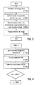
- Step 1100 comprises the step of directing the energy input beams into the ROI.
- This is implemented e.g. with an available radiation or particle source (see below) being directed or focused to emit beams in the plane of ROI.
- the projection profiles are determined. This comprises a direct measurement, if all beams with the same projection direction are directed through ROI simultaneously, as shown in Figure 12.
- the discrete projection profiles are constructed from measurements with fan or cone beam components as illustrated below with reference to Figure 7. In this case, attenuation values measured at different positions of the radiation source are arranged in discrete projection profiles such that all attenuation values being measured with the same projection direction contribute to the same projection profile.
- a first projection direction ⁇ is set (step 1110) and selected in dependence on the operation condition of the imaging device used in practice.
- Setting the projection direction means that the energy generator device (e.g. radiation source) and the detector device are arranged such that a connecting line between both devices runs through the ROI.
- imaging devices e.g. based on the measurement of ultrasound waves, both the ultrasound generator and the detector device are arranged on the same side of ROI.
- the energy generator is activated so that an energy input beam is travelling through or at least into the ROI.
- the detection of attenuation values is conducted with the detector device.
- step 1130 a decision is made whether the full circle has been scanned. If not, the next projection direction is set (step 1110). Otherwise, the projection profiles are determined according to step 1200 in Figure 3.
- FIG. 5 schematically illustrates an embodiment of the imaging device 100.
- the imaging device 100 comprises the measuring device with the energy generator 200 and the detector device 300 and the reconstruction device 400 being connected with the measuring device.
- a holding device 500 is provided, which is e.g. a carrier table as it is known from CT systems or any other carrier or substrate holder for arranging an object under investigation in the measuring device and for adjusting the geometry of the object relative to the energy generator 200 and the detector device 300.
- Further components like a control device, a display device etc. are provided for as they are known per se from prior art devices.
- the energy generator 200 comprises an energy input source 210, like e.g. a movable X-ray arranged on a source carrier 220 (e.g. a guide rail) as it is known from conventional CT devices.
- the detector device comprises a sensor array 310 which is movably arranged on the source carrier 220 in opposite relationship relative to the energy input source 210. With this structure, the projection direction through the ROI (parallel to the plane of drawing) can be set by rotating the combination of components 210, 310 around the holding device 500.
- the source carrier 220 is illustrated as a circle allowing a rotation of the energy generator 200 and the detector device 300 around an object. According to a modification, the source carrier can have an ellipse shape or another shape. This can represent an advantage in terms of an adaptation to the geometry of the object to be investigated.
- the imaging device 100 is structured like a current medical CT-system. Directing a continuous fan or cone beam 5 through ROI 2 in a CT system for collecting projection data is schematically illustrated in Figure 6.
- the CT-system (not completely illustrated) includes the ring-shaped source carrier 220 in which the X-ray tube (radiation source 210) and the detector device 310 are rotating in a way that the whole system can finish a complete turn within e.g. 0.3 to 0.5 s.
- the detector device 310 consists e. g. of 1 to 64 rows of sensor elements (if it is more than one row it would be called a multi-slice-CT) and approximately 700 and 1000 sensor elements per row. Within each single turn the data are read about 1000 times.
- the object under investigation e.g. a patient
- a so-called helical or spiral CT data set can be gathered, because the data that are collected are located on a spiral net (see Figure 14).
- the detector device 310 is a linear or 2-dimensional array of sensor elements being arranged on a spherical reference surface adapted to the radius of the CT-ring. It is an essential advantage of the invention that the provision of a spherical detector device is not necessarily required. Alternatively, a plane detector device with a straight (1-dimensional) or a plane (2-dimensional) arrangement of sensor elements can be used. Although the sensor elements on a plane detector device would not sense attenuation values according to the equally spaced arc length positions mentioned below, this would not influence the quality of the reconstruction according to the invention.
- each fan beam 5 as illustrated in Figure 6 represents a bundle of fan beam components 5.1. 5.2, 5.3 ....
- Each of the fan beam components 5.1, 5.2, 5.3 ... can be considered as a straight pencil beam. While these pencil beams as such do not have the same projection directions, the determination of the discrete projection profiles according to step 1200 in Figure 3 follows a concept which is illustrated in Figure 7.
- Figure 7 illustrates a plurality of fan beams (e.g. fan beam 5) each of which comprising the fan beam components 5.1 to 5.4.
- the fan beam component 5.3 runs through ROI 2 as a straight pencil beam being detected at the sensor element 311 of the detector device 310 (detector array).
- the fan beam component 5.2' of the fan beam 5' radiated at a changed position of the radiation source 210 is detected at the sensor element 312.
- This concept can be used for the reconstruction of image functions from projection data collected with a conventional CT device according to Figure 6.
- the attenuation values for constructing the discrete projection profiles can be simply selected from the collection of raw data obtained with the CT device.
- the discrete fan beam can be generated with a radiation source emitting a continuous fan (or cone) beam combined with a mask that allow only certain components of the continuous fan beam being transmitted through. These components can be considered as straight pencil beams.
- the function of the mask can be fulfilled by the source mask being positioned on the radiation source and being movable therewith, or by a plurality of fixed frame masks being arranged on the source carrier or a ring-shaped shield attached thereto.
- the embodiment using the source mask is preferred as the source mask can be detachable and be positioned on the radiation source.
- a source mask with the appropriate number and spacing of straight beam components can be selected from a set of different source masks and attached to the radiation source.
- the discrete fan beam 6 comprising fan beam components 6.1, 6.2, ... is generated with a radiation source 210 equipped with the source mask 211.
- the source mask 211 is adapted for shaping the energy distribution function of the radiation source 210.
- the source mask 211 comprises a shielding plate 212 for example made by tungsten with through holes 213 as schematically illustrated in Figures 9 and 10.
- the shielding plate 12 can have a spherical shape ( Figure 9) or a plane shape ( Figure 10) or any other appropriate shape adapted to the schematic conditions of the imaging device.
- the through holes 213 are arranged such that the projection lines starting at the radiation source cross the circle in line with the detector elements on at predetermined positions, in particular, they can be arranged with an equal arc length spacing.
- the source mask is fixed to the radiation source (e.g. X-ray tube), in particular to a frame 214 of an output window 215 of the radiation source 210 by a detachable fixing element, like e.g. a clip element or a snap connection.
- the discrete fan beam 6 comprises e.g. 200 straight fan beam components.
- the signals from the sensor elements of the detector device detecting the attenuation along the corresponding projection lines are read-out at certain positions of the radiation source and the detector device only.
- the read out positions are those arc length positions on the ring-shaped source carrier, which fulfil the condition of selecting fan beam components with the same projection directions as illustrated in Figure 7.
- the energy input e.g. radiation
- the sensor element signals are read out only when the combination of a radiation source and the detector device is oriented to the suitable positions.
- this condition is fulfilled for certain times and/or for certain arc length positions of the radiation source.
- the radiation source can be shut off or shielded. Shielding the radiation source is preferred for keeping radiation conditions stable.
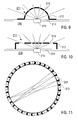
- the shielding function can be fulfilled by a ring-shaped shield 222 which is schematically illustrated in Figure 8 with a plurality of radiation windows 223.
- the ring-shaped shield 222 can be detachably fixed to the source carrier 220 for adapting the geometric properties of the shield 222 to the practical application and in particular to the mask used.
- the ring-shaped shield 222 comprises 201 radiation windows 223 each having a diameter of 6 mm ( with a diameter of the CT-ring: 80 cm).
- each radiation windows 223 of the ring-shaped shield 222 is provided with a frame mask 224 which is illustrated in Figure 8 as an example only. In fact, the source frame masks 211, 224 need not be provided simultaneously.
- FIG 11 An essential advantage of the reconstructing method of the invention that influences the design of the imaging device is illustrated in Figure 11. While the invention has been illustrated in Figures 6 to 10 with a rotating combination of a radiation source and the detector device (which could be fixed to each other or moved separately from each other), the invention allows a data collection with a detector device being fixed in the imaging device. Due to the fact that the invention does not need a continuously varying projection direction but only discrete radiation positions of the radiation source, the spacing between the radiation windows 223 (see above) can be used for positioning sensor elements of the detector device. This situation is shown with radiation windows 223 (empty circles) and sensor elements 313 (full circles) arranged adjacent to the radiation windows 223 ( Figure 11).
- the object under investigation can be irradiated with straight, parallel pencil beams emitted simultaneously at each position of the radiation source 210 as shown in Figure 12.
- the straight parallel pencil beams 7 are distributed on a radiation field, the extension of which is determined by a elongated radiation source.
- the parallel pencil beams 7 are shaped with a mask provided on the radiation source as described above.
- a moving radiation source emitting one pencil beam can be used as it is known from the CT-systems of the first generation.
- the embodiment of Figure 12 has the particular advantage that discrete projection profiles can be directly measured with the detector device 310 without the component selection as shown in Figure 7.
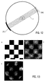
- Figure 13 shows a comparison of an artificial object slice.
- the original object is shown
- the reconstruction with conventional filtered back-projection using 128 projections, with 32 rays per projection is shown
- (c) shows the reconstruction out of 31 projections and 31 rays according to the invention.
- Figure 14 shows the geometric conditions of a helical CT-system and how this can be used with the invention-based reconstruction method.
- the steps between the radiation points should be spaced as it is in the 2D case as seen in Figure 7.
- the above mentioned inner ring of holes can still be used (as in Figure 8).
- the imaging device 100 comprises a fixed arrangement of combined energy generator and detector devices 200, 300 which comprise ultrasound oscillators 210 (converters), ultrasound detectors 310.
- Figure 15 illustrates an arrangement with a rectangular arrangement. A corresponding ring-shaped arrangement is possible as well.
- an object 1 is arranged on the holding device 500.
- the effect of the holding device 500 can be introduced into the adjusted matrix with the calibration mentioned above.
- a coupling fluid is arranged between the object 1 and the ultrasound converters.
- the ultrasound oscillators 210 generate straight ultrasound fields which travel into the object.
- the ultrasound waves are reflected within the object.
- the back-reflection is detected with the ultrasound detector 310 and processed according to the principles outlined above.
- the imaging device 100 comprises an arrangement of electrodes 240, being electrically connected with an impedance measurement device.
- the data being measured as in conventional impedance tomography are used for reconstructing images on the basis of impedance values measured along parallel current directions in the object.
- the method of the invention provides a direct approach for reconstruction of images from Radon data, e.g. in CT.
- the present method is based on orthogonal expansions in terms of orthogonal polynomials of two variables on a disk as outlined in the following.
- the mathematical background is given in Section (3.1), while the preferred approximations are presented in Section (3.2).
- the unit disc is a closed, bounded set with 0 in its interior; is symmetric with respect to 0 (i.e., if q belongs to D, then so does -q); and is convex.
- the set P k : ⁇ 0 ⁇ k ⁇ n ⁇ is an orthonormal basis for ⁇ n 2 .
- the reconstruction method according to the present invention is based on the following remarkable result, which expresses the partial sum S 2m f in terms of the Radon projections.
- T ⁇ k be the Chebyshev polynomial of the first kind.
- T ⁇ k are orthonormal with respect to ( z ( L - z )) -1/2 / ⁇ 2 on [0, L ].
- U k ( ⁇ j,k ; x, y ) be defined as before.
- the set ⁇ P l ;0 ⁇ l ⁇ n ⁇ is an orthonormal basis for ⁇ n 3 .
- S n f denote the Fourier partial sum operator
- R ⁇ ( g;t ) for Radon projection of a function g : B 2 ⁇ R is retained.
- R ⁇ ( f ( . , . , z ) ; t ) ⁇ I ( ⁇ , t ) f ( x ; y ; z ) d x d y
- a quadrature is preferably used according to the invention to get a discrete approximation to the integrals in (1.4) and in (1.7).
- the approximation process A 2m f uses the Radon data ⁇ R ⁇ ⁇ ( f ; t j ) : 0 ⁇ ⁇ ⁇ 2 m , 1 ⁇ j ⁇ n ⁇ of f .
- the data consists of Radon projections on 2m + 1 equally spaced directions along the circumference of the disk (specified by ⁇ ⁇ ) and there are n parallel lines (specified by t j ) in each direction. If these parallel Radon projections are taken from an image f , then the algorithm produces a polynomial A 2m ⁇ which gives an approximation to the original image.
- the polynomial A 2m f is particularly handy for numerical implementation, since one could save T j , v e.g. on a hard disc drive before measurement.
- This provides a very simple algorithm: given the Radon data, one only has to perform addition and multiplication to evaluate A 2m ⁇ ( x ) in (2.1) to get a reconstruction of image.
- the method of the invention can start from some summability methods for the Fourier orthogonal expansion that have better convergence behaviour instead of starting from S 2m f. If the following sampling function (or: multiplier function) is used, advantageously the property that polynomials up to certain degree are preserved is retained. To this end, the sum of polynomials is subjected to a predetermined multiplier function reducing the contributions of polynomials of higher degrees according to the multiplier function.
- sampling function or: multiplier function
- the operator S 2 m ⁇ has better approximation property.
- the operator S 2 m ⁇ preserves polynomials of degree up to m and it approximates f as accurate as, up to a constant multiple, any polynomial of degree at most m.
- the algorithm of the invention is based in this case on the following:
- a 2 m ⁇ f uses the same Radon data of f as A 2 m f. It also has the same simple structure for numerical implementation and it preserves polynomials of degree up to m. Its approximation behaviour appears to be better than that of A 2 m f
- the Gaussian quadrature is used for the integral in z.
- the Gaussian quadrature for ( z ( L - z )) -1/2 is used for the integral in z.
- the same quadrature (1.8) as in the case of B 2 is used.
- the reconstruction algorithm using the Gaussian quadrature (1.9) is described.
- the algorithm produces a polynomial B 2m of three variables as follows:
- the approximation process B 2m uses the Radon data ⁇ R ⁇ ⁇ ( f ( . , . , z i ; cos ⁇ j ) : 0 ⁇ ⁇ ⁇ 2 m , 1 ⁇ j ⁇ 2 m , 0 ⁇ i ⁇ n ⁇ 1 ) ⁇ of f .
- the data consists of Radon projections on n disks that are perpendicular to the z -axis (specified by z i ), on each disk the Radon projections are taken in 2 m + 1 equally spaced directions along the circumference of the disk (specified by ⁇ j ) and 2 m + 1 parallel lines (specified by cos ⁇ j ) in each direction.
- This approximation can be used for the reconstruction of the 3D images from the parallel Radon data.
- the integer n of z-direction should be chosen so that the resolution in the z-direction is comparable to the resolution on each disk.
- the weight function ( z ( L - z )) -1/2 is used instead of the constant weight function.
- the Chebyshev polynomials of the first kind are simple to work with and the corresponding Gaussian quadrature (2.7) is explicit. If the constant weight functions would be used, we would have to work with Legendral polynomials, whose zeros (the nodes of Gaussian quadrature) can be given only numerically.
- the reconstruction algorithm for 3D images can be implemented with a sampling function (multiplier function) in an analogue way as outlined above (section 3.2.2).
Priority Applications (24)
| Application Number | Priority Date | Filing Date | Title |
|---|---|---|---|
| EP04031043A EP1677253A1 (en) | 2004-12-30 | 2004-12-30 | Method and device of reconstructing an (n+1)-dimensional image function from radon data |
| EP05011136A EP1677254A1 (en) | 2004-12-30 | 2005-05-23 | Method and device for collimating an energy input beam |
| EP05817788A EP1831845B1 (en) | 2004-12-30 | 2005-12-21 | Method and device of reconstructing an (n+1)-dimensional image function from radon data |
| AT05819578T ATE497225T1 (de) | 2004-12-30 | 2005-12-21 | Verfahren und einrichtung zum formen eines energieeingangsstrahls |
| US11/794,557 US7573975B2 (en) | 2004-12-30 | 2005-12-21 | Method and device for shaping an energy input beam |
| CN200580045368A CN100595793C (zh) | 2004-12-30 | 2005-12-21 | 用于对能量输入束整形的方法和设备 |
| PCT/EP2005/013802 WO2006069709A1 (en) | 2004-12-30 | 2005-12-21 | Method and device for collimating an energy input beam |
| CA2584900A CA2584900C (en) | 2004-12-30 | 2005-12-21 | Method and device of reconstructing an (n+1)-dimensional image function from radon data |
| DK05817788T DK1831845T3 (da) | 2004-12-30 | 2005-12-21 | Fremgangsmåde og anordning til rekonstruktion af en (n+1)-dimensionel billedfunktion på basis af radon-data |
| KR1020077011035A KR101252010B1 (ko) | 2004-12-30 | 2005-12-21 | 라돈데이터로부터 (n+1)차원 영상 함수를 재구성하는방법과 장치 |
| CNB2005800371424A CN100561520C (zh) | 2004-12-30 | 2005-12-21 | 从Radon数据重建(n+1)维图像函数的方法和设备 |
| CA2589253A CA2589253C (en) | 2004-12-30 | 2005-12-21 | Method and device for shaping an energy input beam |
| ES05817788T ES2308580T3 (es) | 2004-12-30 | 2005-12-21 | Procedimiento y dispositivo de reconstruccion de una funcion imagen de (n+1) dimensiones a partir de datos radon. |
| EP05819578A EP1831846B1 (en) | 2004-12-30 | 2005-12-21 | Method and device for shaping an energy input beam |
| ES05819578T ES2358572T3 (es) | 2004-12-30 | 2005-12-21 | Método y dispositivo para formar un haz de entrada de energía. |
| KR1020077012412A KR101181939B1 (ko) | 2004-12-30 | 2005-12-21 | 에너지 투입 광선을 조절하기 위한 방법 및 장치 |
| US11/794,558 US8081807B2 (en) | 2004-12-30 | 2005-12-21 | Method and device of reconstructing an (n+1)-dimensional image function from radon data |
| DE602005007066T DE602005007066D1 (de) | 2004-12-30 | 2005-12-21 | Verfahren und einrichtung zum rekonstruieren einer |
| AT05817788T ATE396462T1 (de) | 2004-12-30 | 2005-12-21 | Verfahren und einrichtung zum rekonstruieren einer (n+1)-dimensionalen bildfunktion aus radon- daten |
| JP2007548729A JP5340600B2 (ja) | 2004-12-30 | 2005-12-21 | ラドンデータから(n+1)次元イメージ関数を再構成する方法および装置 |
| DE602005026170T DE602005026170D1 (de) | 2004-12-30 | 2005-12-21 | Verfahren und einrichtung zum formen eines energieeingangsstrahls |
| JP2007548730A JP5340601B2 (ja) | 2004-12-30 | 2005-12-21 | エネルギー入力ビームをコリメートするための方法及び装置 |
| PCT/EP2005/013801 WO2006069708A1 (en) | 2004-12-30 | 2005-12-21 | Method and device of reconstructing an (n+1)-dimensional image function from radon data |
| DK05819578.5T DK1831846T3 (da) | 2004-12-30 | 2005-12-21 | Fremgangsmåde og indretning til formning af en energiinputstråle |
Applications Claiming Priority (2)
| Application Number | Priority Date | Filing Date | Title |
|---|---|---|---|
| US64042604P | 2004-12-30 | 2004-12-30 | |
| EP04031043A EP1677253A1 (en) | 2004-12-30 | 2004-12-30 | Method and device of reconstructing an (n+1)-dimensional image function from radon data |
Publications (1)
| Publication Number | Publication Date |
|---|---|
| EP1677253A1 true EP1677253A1 (en) | 2006-07-05 |
Family
ID=38227697
Family Applications (2)
| Application Number | Title | Priority Date | Filing Date |
|---|---|---|---|
| EP04031043A Withdrawn EP1677253A1 (en) | 2004-12-30 | 2004-12-30 | Method and device of reconstructing an (n+1)-dimensional image function from radon data |
| EP05817788A Not-in-force EP1831845B1 (en) | 2004-12-30 | 2005-12-21 | Method and device of reconstructing an (n+1)-dimensional image function from radon data |
Family Applications After (1)
| Application Number | Title | Priority Date | Filing Date |
|---|---|---|---|
| EP05817788A Not-in-force EP1831845B1 (en) | 2004-12-30 | 2005-12-21 | Method and device of reconstructing an (n+1)-dimensional image function from radon data |
Country Status (11)
| Country | Link |
|---|---|
| US (1) | US8081807B2 (ja) |
| EP (2) | EP1677253A1 (ja) |
| JP (1) | JP5340600B2 (ja) |
| KR (1) | KR101252010B1 (ja) |
| CN (1) | CN100561520C (ja) |
| AT (1) | ATE396462T1 (ja) |
| CA (1) | CA2584900C (ja) |
| DE (1) | DE602005007066D1 (ja) |
| DK (1) | DK1831845T3 (ja) |
| ES (1) | ES2308580T3 (ja) |
| WO (1) | WO2006069708A1 (ja) |
Cited By (10)
| Publication number | Priority date | Publication date | Assignee | Title |
|---|---|---|---|---|
| EP1780676A1 (en) | 2005-10-25 | 2007-05-02 | GSF-Forschungszentrum für Umwelt und Gesundheit GmbH | Imaging method and device with dual reading scanner |
| EP1818871A1 (en) | 2006-02-10 | 2007-08-15 | GSF-Forschungszentrum für Umwelt und Gesundheit GmbH | Scattered radiation correction of detector signals for projection-based imaging |
| EP1959395A1 (en) * | 2007-02-14 | 2008-08-20 | Helmholtz Zentrum München Deutsches Forschungszentrum für Gesundheit und Umwelt (GmbH) | Method of processing a radon data based image function and imaging method |
| WO2010063482A1 (en) * | 2008-12-05 | 2010-06-10 | Helmholtz Zentrum München Deutsches Forschungszentrum Für Gesundheit Und Umwelt (Gmbh) | Reconstructing a tomographic image reduced artifacts |
| EP2250967A1 (en) * | 2009-05-13 | 2010-11-17 | Helmholtz Zentrum München Deutsches Forschungszentrum für Gesundheit und Umwelt (GmbH) | Tomography apparatus and tomography method |
| WO2010133994A1 (en) | 2009-05-20 | 2010-11-25 | Koninklijke Philips Electronics N.V. | Data acquisition and visualization mode for low dose intervention guidance in computed tomography |
| US8094910B2 (en) | 2006-03-14 | 2012-01-10 | State Of Oregon Acting By And Through The State Board Of Higher Education On Behalf Of The University Of Oregon | Method of reconstructing an image function from Radon data |
| US8243875B2 (en) | 2005-05-23 | 2012-08-14 | State of Oregon acting by and through the State Board of Higher Education | Method and device for imaging tomography |
| CN102869306A (zh) * | 2010-05-03 | 2013-01-09 | 皇家飞利浦电子股份有限公司 | 用于产生感兴趣对象的成角视图的医学观察系统和方法 |
| CN112068179A (zh) * | 2020-08-13 | 2020-12-11 | 南昌大学 | 一种基于勒贝格采样的正电子成像方法 |
Families Citing this family (27)
| Publication number | Priority date | Publication date | Assignee | Title |
|---|---|---|---|---|
| US10483077B2 (en) | 2003-04-25 | 2019-11-19 | Rapiscan Systems, Inc. | X-ray sources having reduced electron scattering |
| GB0812864D0 (en) | 2008-07-15 | 2008-08-20 | Cxr Ltd | Coolign anode |
| US9208988B2 (en) | 2005-10-25 | 2015-12-08 | Rapiscan Systems, Inc. | Graphite backscattered electron shield for use in an X-ray tube |
| US8094784B2 (en) | 2003-04-25 | 2012-01-10 | Rapiscan Systems, Inc. | X-ray sources |
| GB0525593D0 (en) | 2005-12-16 | 2006-01-25 | Cxr Ltd | X-ray tomography inspection systems |
| US8243876B2 (en) | 2003-04-25 | 2012-08-14 | Rapiscan Systems, Inc. | X-ray scanners |
| US9046465B2 (en) | 2011-02-24 | 2015-06-02 | Rapiscan Systems, Inc. | Optimization of the source firing pattern for X-ray scanning systems |
| US8170316B2 (en) * | 2007-10-01 | 2012-05-01 | California Institute Of Technology | Tomographic imaging with a stripe-like shaped sensor |
| EP2130494A1 (en) | 2008-06-06 | 2009-12-09 | Helmholtz Zentrum München Deutsches Forschungszentrum für Gesundheit und Umwelt (GmbH) | Scanner device and method for computed tomography imaging |
| GB0816823D0 (en) | 2008-09-13 | 2008-10-22 | Cxr Ltd | X-ray tubes |
| GB0901338D0 (en) | 2009-01-28 | 2009-03-11 | Cxr Ltd | X-Ray tube electron sources |
| GB2468164B (en) * | 2009-02-27 | 2014-08-13 | Samsung Electronics Co Ltd | Computer-aided detection of lesions |
| CN102081697B (zh) * | 2009-11-27 | 2013-12-11 | 深圳迈瑞生物医疗电子股份有限公司 | 一种在超声成像空间中定义感兴趣容积的方法及其装置 |
| US20120162216A1 (en) * | 2010-12-22 | 2012-06-28 | Electronics And Telecommunications Research Institute | Cylindrical three-dimensional image display apparatus and method |
| US20120238876A1 (en) * | 2011-03-18 | 2012-09-20 | Fujifilm Corporation | Ultrasound diagnostic apparatus and method of producing ultrasound image |
| BE1019941A3 (nl) * | 2012-06-05 | 2013-02-05 | Tait Technologies Bvba | Inrichting voor de weergave van driedimensionale beelden, systeem voor de creatie van driedimensionale beelden, en werkwijze voor de creatie van driedimensionale beelden. |
| CN104486997B (zh) * | 2012-06-05 | 2017-07-25 | 拉皮斯坎系统股份有限公司 | X射线扫描系统的射线源激发模式的最佳化 |
| DE102012217940A1 (de) | 2012-10-01 | 2014-04-03 | Siemens Aktiengesellschaft | Rekonstruktion von Bilddaten |
| DE102012219269A1 (de) * | 2012-10-22 | 2014-05-08 | Fraunhofer-Gesellschaft zur Förderung der angewandten Forschung e.V. | Verfahren und Vorrichtung zum Erzeugen einer dreidimensionalen Abbildung eines Objekts |
| US10585206B2 (en) | 2017-09-06 | 2020-03-10 | Rapiscan Systems, Inc. | Method and system for a multi-view scanner |
| EP3469988A1 (en) * | 2017-10-11 | 2019-04-17 | Ion Beam Applications S.A. | Apparatus and methods for imaging an object by cone beam tomography |
| WO2019230741A1 (ja) | 2018-05-28 | 2019-12-05 | 国立研究開発法人理化学研究所 | 角度オフセットによる断層画像データの取得方法、取得装置、および制御プログラム |
| JP7236110B2 (ja) * | 2018-05-28 | 2023-03-09 | 国立研究開発法人理化学研究所 | オーバーサンプリングによる断層画像データの取得方法、取得装置、および制御プログラム |
| CN110276772B (zh) * | 2019-05-10 | 2022-10-18 | 深圳大学 | 一种肌肉组织中结构要素的自动定位方法及系统 |
| CN110400253B (zh) * | 2019-07-02 | 2023-03-17 | 西安工业大学 | 一种基于双线性插值原理确定发射层析权重矩阵的方法 |
| US11212902B2 (en) | 2020-02-25 | 2021-12-28 | Rapiscan Systems, Inc. | Multiplexed drive systems and methods for a multi-emitter X-ray source |
| KR102203984B1 (ko) * | 2020-07-01 | 2021-01-18 | (주)뉴클리어엔지니어링 | 중성자 선원에 의한 지뢰 탐지 장치 및 이를 이용한 중성자 선원에 의한 지뢰 탐지 방법 |
Family Cites Families (8)
| Publication number | Priority date | Publication date | Assignee | Title |
|---|---|---|---|---|
| US4315157A (en) * | 1980-05-01 | 1982-02-09 | The University Of Alabama In Birmingham | Multiple beam computed tomography (CT) scanner |
| US5592523A (en) * | 1994-12-06 | 1997-01-07 | Picker International, Inc. | Two dimensional detector array for CT scanners |
| US6282257B1 (en) * | 1999-06-23 | 2001-08-28 | The Board Of Trustees Of The University Of Illinois | Fast hierarchical backprojection method for imaging |
| US6343110B1 (en) * | 2000-07-25 | 2002-01-29 | Ge Medical Systems Global Technology Company, Llc | Methods and apparatus for submillimeter CT slices with increased coverage |
| WO2003027954A2 (en) * | 2001-09-26 | 2003-04-03 | Massachusetts Institute Of Technology | Versatile cone-beam imaging apparatus and method |
| US7227982B2 (en) * | 2002-04-15 | 2007-06-05 | General Electric Company | Three-dimensional reprojection and backprojection methods and algorithms for implementation thereof |
| EP1780676A1 (en) * | 2005-10-25 | 2007-05-02 | GSF-Forschungszentrum für Umwelt und Gesundheit GmbH | Imaging method and device with dual reading scanner |
| EP1835464A1 (en) * | 2006-03-14 | 2007-09-19 | GSF-Forschungszentrum für Umwelt und Gesundheit GmbH | Method of reconstructing an image function from radon data |
-
2004
- 2004-12-30 EP EP04031043A patent/EP1677253A1/en not_active Withdrawn
-
2005
- 2005-12-21 KR KR1020077011035A patent/KR101252010B1/ko not_active IP Right Cessation
- 2005-12-21 AT AT05817788T patent/ATE396462T1/de active
- 2005-12-21 JP JP2007548729A patent/JP5340600B2/ja not_active Expired - Fee Related
- 2005-12-21 ES ES05817788T patent/ES2308580T3/es active Active
- 2005-12-21 CA CA2584900A patent/CA2584900C/en not_active Expired - Fee Related
- 2005-12-21 US US11/794,558 patent/US8081807B2/en not_active Expired - Fee Related
- 2005-12-21 CN CNB2005800371424A patent/CN100561520C/zh not_active Expired - Fee Related
- 2005-12-21 WO PCT/EP2005/013801 patent/WO2006069708A1/en active IP Right Grant
- 2005-12-21 DE DE602005007066T patent/DE602005007066D1/de active Active
- 2005-12-21 DK DK05817788T patent/DK1831845T3/da active
- 2005-12-21 EP EP05817788A patent/EP1831845B1/en not_active Not-in-force
Non-Patent Citations (2)
| Title |
|---|
| BORTFELD T ET AL: "Fast and exact 2D image reconstruction by means of Chebyshev decomposition and backprojection", PHYSICS IN MEDICINE AND BIOLOGY, vol. 44, no. 4, April 1999 (1999-04-01), IOP PUBLISHING UK, pages 1105 - 1120, XP002317721, ISSN: 0031-9155 * |
| HANSON K M ET AL: "Local basis-function approach to computed tomography", APPLIED OPTICS USA, vol. 24, no. 23, 1 December 1985 (1985-12-01), pages 4028 - 4039, XP002317722, ISSN: 0003-6935 * |
Cited By (17)
| Publication number | Priority date | Publication date | Assignee | Title |
|---|---|---|---|---|
| US8243875B2 (en) | 2005-05-23 | 2012-08-14 | State of Oregon acting by and through the State Board of Higher Education | Method and device for imaging tomography |
| EP1780676A1 (en) | 2005-10-25 | 2007-05-02 | GSF-Forschungszentrum für Umwelt und Gesundheit GmbH | Imaging method and device with dual reading scanner |
| EP1818871A1 (en) | 2006-02-10 | 2007-08-15 | GSF-Forschungszentrum für Umwelt und Gesundheit GmbH | Scattered radiation correction of detector signals for projection-based imaging |
| US8094910B2 (en) | 2006-03-14 | 2012-01-10 | State Of Oregon Acting By And Through The State Board Of Higher Education On Behalf Of The University Of Oregon | Method of reconstructing an image function from Radon data |
| EP1959395A1 (en) * | 2007-02-14 | 2008-08-20 | Helmholtz Zentrum München Deutsches Forschungszentrum für Gesundheit und Umwelt (GmbH) | Method of processing a radon data based image function and imaging method |
| WO2008098711A1 (en) * | 2007-02-14 | 2008-08-21 | Helmholtz Zentrum München Deutsches Forschungszentrum Für Gesundheit Und Umwelt (Gmbh) | Method of processing a radon data based image function and imaging method |
| JP2010518524A (ja) * | 2007-02-14 | 2010-05-27 | ヘルムホルツ・ツェントルム・ミュンヒェン・ドイチェス・フォルシュンクスツェントルム・フューア・ゲズントハイト・ウント・ウムベルト(ゲーエムベーハー) | ラドンデータに基づくイメージ関数を処理する方法並びに撮像方法 |
| US8630466B2 (en) | 2007-02-14 | 2014-01-14 | State Of Oregon Acting By And Through The State Board Of Higher Education On Behalf Of The University Of Oregon | Method of processing a Radon data based image function and imaging method |
| US8571171B2 (en) | 2008-12-05 | 2013-10-29 | Helmholtz Zentrum Munchen Deutsches Forschungszentrum Fur Gesundheit Und Umwelt (Gmbh) | Reconstructing a tomographic image with reduced artifacts |
| WO2010063482A1 (en) * | 2008-12-05 | 2010-06-10 | Helmholtz Zentrum München Deutsches Forschungszentrum Für Gesundheit Und Umwelt (Gmbh) | Reconstructing a tomographic image reduced artifacts |
| WO2010130394A1 (en) * | 2009-05-13 | 2010-11-18 | Helmholtz Zentrum München Deutsches Forschungszentrum Für Gesundheit Und Umwelt (Gmbh) | Tomography apparatus and tomography method |
| EP2250967A1 (en) * | 2009-05-13 | 2010-11-17 | Helmholtz Zentrum München Deutsches Forschungszentrum für Gesundheit und Umwelt (GmbH) | Tomography apparatus and tomography method |
| US8971481B2 (en) | 2009-05-13 | 2015-03-03 | Helmholtz Zentrum Munchen Deutsches Forschungszentrum für Gesundheit und Umwelt (GmbH) | Tomography apparatus and tomography method |
| WO2010133994A1 (en) | 2009-05-20 | 2010-11-25 | Koninklijke Philips Electronics N.V. | Data acquisition and visualization mode for low dose intervention guidance in computed tomography |
| CN102869306A (zh) * | 2010-05-03 | 2013-01-09 | 皇家飞利浦电子股份有限公司 | 用于产生感兴趣对象的成角视图的医学观察系统和方法 |
| CN102869306B (zh) * | 2010-05-03 | 2015-07-08 | 皇家飞利浦电子股份有限公司 | 用于产生感兴趣对象的成角视图的医学观察系统和方法 |
| CN112068179A (zh) * | 2020-08-13 | 2020-12-11 | 南昌大学 | 一种基于勒贝格采样的正电子成像方法 |
Also Published As
| Publication number | Publication date |
|---|---|
| CA2584900A1 (en) | 2006-07-06 |
| US8081807B2 (en) | 2011-12-20 |
| CA2584900C (en) | 2013-12-03 |
| KR101252010B1 (ko) | 2013-04-12 |
| US20080130974A1 (en) | 2008-06-05 |
| WO2006069708A1 (en) | 2006-07-06 |
| CN101048802A (zh) | 2007-10-03 |
| JP5340600B2 (ja) | 2013-11-13 |
| DK1831845T3 (da) | 2008-09-15 |
| EP1831845A1 (en) | 2007-09-12 |
| DE602005007066D1 (de) | 2008-07-03 |
| EP1831845B1 (en) | 2008-05-21 |
| JP2008526283A (ja) | 2008-07-24 |
| KR20070103733A (ko) | 2007-10-24 |
| CN100561520C (zh) | 2009-11-18 |
| ES2308580T3 (es) | 2008-12-01 |
| ATE396462T1 (de) | 2008-06-15 |
Similar Documents
| Publication | Publication Date | Title |
|---|---|---|
| EP1831845B1 (en) | Method and device of reconstructing an (n+1)-dimensional image function from radon data | |
| US7251307B2 (en) | Fan-beam and cone-beam image reconstruction using filtered backprojection of differentiated projection data | |
| Mueller et al. | Reconstructive tomography and applications to ultrasonics | |
| EP1941457B1 (en) | Imaging method and device with dual reading scanner | |
| JP5221394B2 (ja) | ラドンデータから画像関数を再構成する方法 | |
| JP5198443B2 (ja) | 画像の分解能を高めるシステム及び方法 | |
| EP1800264B1 (en) | Image reconstruction with voxel dependent interpolation | |
| JP2007512034A (ja) | 発散ビームスキャナのための画像再構成方法 | |
| US6292526B1 (en) | Methods and apparatus for preprocessing volumetric computed tomography data | |
| JP2008538293A (ja) | コンピュータ断層撮影方法、及びコンピュータ断層撮影装置 | |
| Nagarajan et al. | Proficient reconstruction algorithms for low-dose X-ray tomography | |
| Leahy et al. | Computed tomography | |
| DENİZ | Modern Computer Tomography with Artificial Intelligence and Deep Learning Applications | |
| Morotti | Reconstruction of 3D X-ray tomographic images from sparse data with TV-based methods | |
| Al-anbari et al. | Design and Construction Three-Dimensional Head Phantom Test Image for the Algorithms of 3D Image Reconstruction | |
| Cierniak et al. | Spiral Tomography | |
| Karikh | Numerical efficiency of the pipeline algorithm of three-dimensional tomography |
Legal Events
| Date | Code | Title | Description |
|---|---|---|---|
| PUAI | Public reference made under article 153(3) epc to a published international application that has entered the european phase |
Free format text: ORIGINAL CODE: 0009012 |
|
| AK | Designated contracting states |
Kind code of ref document: A1 Designated state(s): AT BE BG CH CY CZ DE DK EE ES FI FR GB GR HU IE IS IT LI LT LU MC NL PL PT RO SE SI SK TR |
|
| AX | Request for extension of the european patent |
Extension state: AL BA HR LV MK YU |
|
| RIN1 | Information on inventor provided before grant (corrected) |
Inventor name: HOESCHEN, CHRISTOPH Inventor name: TISCHENKO, OLEG Inventor name: XU, YUAN |
|
| 17P | Request for examination filed |
Effective date: 20061018 |
|
| 17Q | First examination report despatched |
Effective date: 20061211 |
|
| AKX | Designation fees paid |
Designated state(s): AT BE BG CH CY CZ DE DK EE ES FI FR GB GR HU IE IS IT LI LT LU MC NL PL PT RO SE SI SK TR |
|
| GRAP | Despatch of communication of intention to grant a patent |
Free format text: ORIGINAL CODE: EPIDOSNIGR1 |
|
| STAA | Information on the status of an ep patent application or granted ep patent |
Free format text: STATUS: THE APPLICATION IS DEEMED TO BE WITHDRAWN |
|
| 18D | Application deemed to be withdrawn |
Effective date: 20070915 |