EP1676940A2 - Demarrage de cellules d'extraction électrolytique d'aluminium - Google Patents
Demarrage de cellules d'extraction électrolytique d'aluminium Download PDFInfo
- Publication number
- EP1676940A2 EP1676940A2 EP06004040A EP06004040A EP1676940A2 EP 1676940 A2 EP1676940 A2 EP 1676940A2 EP 06004040 A EP06004040 A EP 06004040A EP 06004040 A EP06004040 A EP 06004040A EP 1676940 A2 EP1676940 A2 EP 1676940A2
- Authority
- EP
- European Patent Office
- Prior art keywords
- aluminium
- cell
- cathode
- layer
- cathode surface
- Prior art date
- Legal status (The legal status is an assumption and is not a legal conclusion. Google has not performed a legal analysis and makes no representation as to the accuracy of the status listed.)
- Withdrawn
Links
Images
Classifications
-
- C—CHEMISTRY; METALLURGY
- C25—ELECTROLYTIC OR ELECTROPHORETIC PROCESSES; APPARATUS THEREFOR
- C25C—PROCESSES FOR THE ELECTROLYTIC PRODUCTION, RECOVERY OR REFINING OF METALS; APPARATUS THEREFOR
- C25C3/00—Electrolytic production, recovery or refining of metals by electrolysis of melts
- C25C3/06—Electrolytic production, recovery or refining of metals by electrolysis of melts of aluminium
- C25C3/08—Cell construction, e.g. bottoms, walls, cathodes
-
- C—CHEMISTRY; METALLURGY
- C04—CEMENTS; CONCRETE; ARTIFICIAL STONE; CERAMICS; REFRACTORIES
- C04B—LIME, MAGNESIA; SLAG; CEMENTS; COMPOSITIONS THEREOF, e.g. MORTARS, CONCRETE OR LIKE BUILDING MATERIALS; ARTIFICIAL STONE; CERAMICS; REFRACTORIES; TREATMENT OF NATURAL STONE
- C04B41/00—After-treatment of mortars, concrete, artificial stone or ceramics; Treatment of natural stone
- C04B41/009—After-treatment of mortars, concrete, artificial stone or ceramics; Treatment of natural stone characterised by the material treated
-
- C—CHEMISTRY; METALLURGY
- C04—CEMENTS; CONCRETE; ARTIFICIAL STONE; CERAMICS; REFRACTORIES
- C04B—LIME, MAGNESIA; SLAG; CEMENTS; COMPOSITIONS THEREOF, e.g. MORTARS, CONCRETE OR LIKE BUILDING MATERIALS; ARTIFICIAL STONE; CERAMICS; REFRACTORIES; TREATMENT OF NATURAL STONE
- C04B41/00—After-treatment of mortars, concrete, artificial stone or ceramics; Treatment of natural stone
- C04B41/45—Coating or impregnating, e.g. injection in masonry, partial coating of green or fired ceramics, organic coating compositions for adhering together two concrete elements
- C04B41/459—Temporary coatings or impregnations
-
- C—CHEMISTRY; METALLURGY
- C04—CEMENTS; CONCRETE; ARTIFICIAL STONE; CERAMICS; REFRACTORIES
- C04B—LIME, MAGNESIA; SLAG; CEMENTS; COMPOSITIONS THEREOF, e.g. MORTARS, CONCRETE OR LIKE BUILDING MATERIALS; ARTIFICIAL STONE; CERAMICS; REFRACTORIES; TREATMENT OF NATURAL STONE
- C04B41/00—After-treatment of mortars, concrete, artificial stone or ceramics; Treatment of natural stone
- C04B41/45—Coating or impregnating, e.g. injection in masonry, partial coating of green or fired ceramics, organic coating compositions for adhering together two concrete elements
- C04B41/52—Multiple coating or impregnating multiple coating or impregnating with the same composition or with compositions only differing in the concentration of the constituents, is classified as single coating or impregnation
-
- C—CHEMISTRY; METALLURGY
- C25—ELECTROLYTIC OR ELECTROPHORETIC PROCESSES; APPARATUS THEREFOR
- C25C—PROCESSES FOR THE ELECTROLYTIC PRODUCTION, RECOVERY OR REFINING OF METALS; APPARATUS THEREFOR
- C25C3/00—Electrolytic production, recovery or refining of metals by electrolysis of melts
- C25C3/06—Electrolytic production, recovery or refining of metals by electrolysis of melts of aluminium
Definitions
- the invention relates to the starting up of cells for the electrowinning of aluminium by the electrolysis of alumina in a cryolite-based melt, which cell comprises a conductive cell bottom on which, in use, aluminium is produced and forms a layer or pool atop which is the molten cryolite electrolyte.
- the invention is particularly but not exclusively concerned with the start up of such cells where the cathode surface is protected by an aluminium-wettable refractory coating.
- Aluminium is produced conventionally by the Hall-Héroult process, by the electrolysis of alumina dissolved in cryolite-based molten electrolytes at temperatures up to around 950°C.
- a Hall-Héroult reduction cell typically has a steel shell provided with an insulating lining of refractory material, which in turn has a lining of carbon which contacts the molten constituents.
- Conductor bars connected to the negative pole of a direct current source are embedded in the carbon cathode substrate forming the cell bottom floor.
- the cathode substrate is usually an anthracite based carbon lining made of prebaked cathode blocks, joined with a ramming mixture of anthracite, coke, and coal tar or resins.
- a molten aluminium pool acts as the cathode.
- the carbon lining or cathode material has a useful life of three to eight years, or even less under adverse conditions.
- the deterioration of the cathode bottom is due to erosion and penetration of electrolyte and liquid aluminium as well as intercalation of sodium, which causes swelling and deformation of the cathode carbon blocks and ramming mix.
- the penetration of sodium species and other ingredients of cryolite or air leads to the formation of toxic compounds including cyanides.
- aluminium electrowinning cells When they are put into service, aluminium electrowinning cells must be preheated. When the cell has reached a sufficient temperature, molten cryolite electrolyte is added and the start-up is continued until the cell reaches an equilibrium operating condition.
- One known cell start-up procedure comprises applying a layer of coke or similar conductive material to the cell bottom and passing an electric current via anodes and through the coke into the cell bottom to heat the cell by the Joule effect.
- Another known cell start-up procedure uses flame burners.
- US Patent 4,405,433 Payne
- Another object of the invention is to protect the cathode by covering it with a temporary protective material before preheating the cell.
- a further object of the invention is to provide a temporary protective material which is at least partially eliminated by the beginning of normal use of the cell, such that it does not contaminate the product aluminium with the temporary protective material.
- the invention in particular relates to a method of protecting during the start-up procedure a cathode of a cell for the electrowinning of aluminium by the electrolysis of alumina dissolved in a fluoride-based melt such as cryolite, on which cathode, in use, aluminium is produced and forms a layer or pool.
- the start-up procedure comprises applying before preheating the cell one or more start-up layers on the cathode surface.
- the method of protection of the invention is characterized in that the start-up layer(s) form(s) a temporary protection against damage of chemical and/or mechanical origin to the cathode, this temporary protection being in intimate contact with the cathode surface and being at least partly eliminated before or during the initial normal operation of the cell.
- the temporary protection may either be "washed away” by normal operation of the cell or permanently integrated into the cathode surface.
- the temporary protection remains in intimate contact with the cathode surface below a layer of molten aluminium during the cell start-up.
- the applied layer melts during start-up and is merely integrated to the pool of product aluminium without preventing melting electrolyte from attacking the aluminium-wettable coating.
- start-up layers may for example be obtained from the following materials:
- the cathode mass can be made mainly of carbonaceous material, such as compacted powdered carbon, a carbon-based paste for example as described in U.S. Patent No. 5,362,366 (Sekhar et al), prebaked carbon blocks assembled together on the shell, or graphite blocks, plates or tiles.
- the cathode is also possible for the cathode to be made mainly of an electrically-conductive carbon-free material, of a composite material made of an electrically-conductive material and an electrically non-conductive material, or of an electrically non-conductive material.
- Such non-conductive carbon-free materials can be alumina, cryolite, or other refractory oxides, nitrides, carbides or combinations thereof and the conductive materials can be at least one metal from Groups IIA, IIB, IIIA, IIIB, IVB, VB and the Lanthanide series of the Periodic Table, in particular aluminium, titanium, zinc, magnesium, niobium, yttrium or cerium, and alloys and intermetallic compounds thereof.
- the composite material's metal preferably has a melting point from 650°C to 970°C.
- the composite material is advantageously a mass made of alumina and aluminium or an aluminium alloy, see U.S. Patent No. 9,650,552 (de Nora et al), or a mass made of alumina, titanium diboride and aluminium or an aluminium alloy.
- the composite material can also be obtained by micropyretic reaction such as that utilizing, as reactants, TiO 2 , B 2 O 3 and A1.
- the cathode can also be made of a combination of at least two materials from : at least one carbonaceous material as mentioned above; at least one electrically conductive non-carbon material; and at least one composite material of an electrically conductive material and an electrically non-conductive material, as mentioned above.
- the cathode surface is coated with an aluminium-wettable refractory material, such as a refractory hard metal boride.
- a refractory hard metal boride may for instance be included in a colloidal carrier and then applied to the cathode surface, i.e. according to the teaching of the aforesaid US Patent 5, 651, 874 (Sekhar/de Nora).
- the foil When an aluminium foil is used as a start-up layer, the foil is preferably from 0.03 to 0.05 mm thick. Eventually, the foil may be oxidised during heating and incorporated (as alumina) into the cathode surface or into a coating of aluminium-wettable refractory material.
- a thick aluminium sheet in combination with a protective layer according to the invention, e.g. including aluminium foils.
- a metallization may be used in order to protect the cathode surface.
- the metallization which can be intimately bonded to the cathode surface, combines chemical, mechanical and electrical properties useful for the start-up procedure.
- This type of start-up layer prevents damage to the cathode of chemical and/or mechanical origin and additionally, the good conductivity of the material may be advantageously used during the cell heating procedure when achieved by the Joule effect as described hereafter.
- Typical metals which may be used for a metallization are aluminium, nickel, iron, titanium, cobalt, chromium, vanadium, zirconium, hafnium, niobium, tantalum, molybdenum, cerium, copper, and their alloys or intermetallics comprising aluminium.
- metallic paints obtained from metallic powder applied in an aqueous, non-aqueous liquid or in an aqueous liquid containing organics, in particular in a polymer, such as polyurethane, ethylene glycol, polyethylene glycol, resins, esters or waxes may be very convenient due to their good protective properties and the ease with which such a material may be applied on the surface of the cell bottom.
- the constituents and the amount of the protective metallization will be chosen so that there is an adequate protection during cell start-up but no undesirable contamination of the aluminium produced. Such metallization may also assist wetting of a porous refractory surface with molten aluminium.
- the protective metallization will usually not remain permanently on the surface of the cathode or on an aluminium-wettable refractory coating, but will be either "washed away” or integrated into the aluminium-wettable coating by the time the cell reaches its normal steady state operation.
- an aluminium paint can be applied on the cell bottom and then covered with a plurality of foils of aluminium as described above.
- intermetallic compounds may be used to protect the cell bottom.
- These compounds may comprise aluminium with a further material selected from nickel, iron, titanium, cobalt, chromium, zirconium or combinations thereof.
- a layer of intermetallic compound is advantageously formed by applying on top of the cell bottom a combination of either aluminium powder, sheet, mesh or porous body such as foam on top of a sheet, mesh or porous body of said further material, or vice-versa. Heating the two metals before or during preheating of the cell initiates a spontaneous reaction for the production of an intermetallic component. Normally, such a layer is then evacuated with the produced molten aluminium before or during the initial normal operation of the cell.
- NiAl or Ni 3 Al as an intermetallic layer is particularly beneficial.
- NiAl is remarkably stable when exposed to heat, the melting point being at about 1600°C. Additionally it presents good mechanical characteristics.
- Another type of protective start-up layer may be obtained at least partly from a boron-containing solution that forms a glassy layer.
- the boron solution can be made from boron oxide, boric acid or tetraboric acid in an aqueous, non-aqueous or aqueous containing organics solvent such as methanol, ethylene glycol, glycerine, water or mixtures thereof.
- the solution may comprise particulate metal that enhances the conductivity of the layer.
- a protective start-up layer may be obtained at least partly from a polymer or polymer precursor, such as polyurethane, ethylene glycol, polyethylene glycol, resins, esters or waxes.
- a polymer or polymer precursor such as polyurethane, ethylene glycol, polyethylene glycol, resins, esters or waxes.
- the electrical conductivity of such a layer may be enhanced by adding particulate conductive material, optionally mixed with borides and/or carbides.
- a further alternative is to form a protective start-up layer from an aqueous and/or non-aqueous solution containing phosphates of aluminium, such as monoaluminium phosphate, aluminium phosphate, aluminium polyphosphate, aluminium metaphosphate and mixtures thereof, for instance dissolved in water.
- phosphates of aluminium such as monoaluminium phosphate, aluminium phosphate, aluminium polyphosphate, aluminium metaphosphate and mixtures thereof, for instance dissolved in water.
- Such a protective start-up layer is advantageously covered with a plurality of foils of aluminium as described above.
- the colloid is preferably selected from colloidal alumina, silica, yttria, ceria, thoria, zirconia, magnesia, lithia, monoaluminium phosphate, cerium acetate or a mixture thereof.
- the colloid solution usually gels during preheating of the cell and protects the cathode and if present the aluminium-wettable refractory coating during this critical start-up phase.
- the colloid from the start-up layer may be at least partially incorporated into the cathode surface or the aluminium-wettable coating.
- Such a protective start-up layer advantageously contains a particulate conductor, such as particulate aluminium, nickel, iron, titanium, cobalt, chromium, zirconium, copper and combinations thereof, in order to improve the conductivity of the start-up layer and additionally to avoid uneven current distribution.
- a protective start-up layer comprising colloidal alumina can be used in combination with at least one pliable foil of aluminium having a thickness of less than 0.1 mm. For instance one or more aluminium foils can be sandwiched with the colloidal alumina.
- protective material is either intimately merged or is in intimate contact with the porous surface of the aluminium-wettable refractory coating and may be partly (or wholly) permanently incorporated in this coating, or partly or wholly removed as the cell reaches its steady state operation.
- Additives such as particulate aluminium, or borides and/or carbides may be added to any protective start-up layer described hereabove before preheating the cell. Such addition enhances the protective effect of the temporary protection.
- the borides and/or carbides may be selected from the following metals: aluminium, titanium, chromium, vanadium, zirconium, hafnium, niobium, tantalum, molybdenum and cerium.
- pliable foils or thick sheets of aluminium may be added on top of any protective start-up layer described hereabove.
- heat can be generated in the conductive material to preheat the cell bottom by passing electric current via anodes and through conductive material such as resistor coke into the cell bottom to heat the cell by the Joule effect.
- the temporary protection preferably has good electrical conductivity.
- the conductivity of a layer may however be enhanced by adding conductive material as described above.
- aluminium powder may be incorporated to a non-inherently conductive or poorly conductive material and therefore even thick layers of poorly conductive based material may be used for protecting the aluminium-wettable coating.
- a relatively thick sheet or sheets of aluminium usually from 1 to 5 mm thick, preferably 3 to 5 mm, can placed between each anode and the temporary protection, in particular on top of the temporary protection.
- This thick sheet of aluminium serves to assist the distribution of the electrical current evenly, and hence avoid hot-spots.
- the cell bottom can be flame preheated by burners providing precautions are taken to avoid direct contact of the flame with a thin protective start-up layer, e.g. by covering it with a layer of coke or other heat-conductive material.
- a thin protective start-up layer e.g. by covering it with a layer of coke or other heat-conductive material.
- Another method to heat the cell during the start-up procedure involves radiation techniques.
- a light source may be used in order to transfer heat to the cell in form of light waves.
- the preferred emitted wavelengths correspond to the infrared spectrum. This technique offers the advantage of avoiding pollution of the cell with undesired elements as when using the flame or the carbon resistor technique.
- the layer of coke or other conductive material can be mixed with and/or covered with a halide-based electrolyte having a point of fusion in the region 660°-760°C.
- Molten cryolite is added to the cell when the temperature of the cell exceeds the point of fusion of said halide-based electrolyte added to the conductive material.
- This halide-based electrolyte can be mixed with or covered with a layer of conductive material such as coke.
- Optionally protective start-up layers may extend to cover other components, such as cell side walls.
- the protection may even extend above the level of the fluoride-based melt reached during normal use of the cell.
- Vapour deposition techniques such as chemical vapour deposition (CVD) or physical vapour deposition (PVD) may be used, or plasma spraying. Chemical or electrodeposition may be advantageously used considering the electrolytic cell environment.
- CVD chemical vapour deposition
- PVD physical vapour deposition
- a foil When a foil is included in the protective layer, such as an aluminium foil, it can be secured on the cell bottom using adhesive application or hot-pressing which gives good results in case of powdery precursors as well.
- the invention also relates to a method of electrowinning aluminium.
- the method comprises two steps namely a start-up procedure with a temporary protection as described hereabove followed by the production of aluminium.
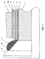
- Figure 1 shows part of an aluminium electrowinning cell comprising a cathode cell bottom 1, for example carbon, coated with an aluminium-wettable refractory material 2, in particular a slurry-applied titanium diboride coating as described in US patent 5,651,874 (Sekhar/de Nora).
- the coating 2 is covered with a temporary protection 3, for example a couple of thin aluminium foils each having a thickness of 0.04 mm, against damage of chemical and/or mechanical origin to the aluminium-wettable coating 2 during the start-up procedure.
- a temporary protection 3 for example a couple of thin aluminium foils each having a thickness of 0.04 mm, against damage of chemical and/or mechanical origin to the aluminium-wettable coating 2 during the start-up procedure.
- other protective layers can be applied, for example those described in Examples II to V below.
- On the temporary protection 3 a thick sheet of aluminium 4 (i.e. having a thickness of 4 mm) is applied.
- the aluminium sheet 4 is covered with resistor coke 5 up to the bottom of the anode 6 which is facing the cathode.
- the resistor coke 5 may extend along the temporary protection or be confined under the anode 6 as indicated by the dashed line 5a.
- the temporary protection 3 extends up a wedge 7 connecting the cathode cell bottom 1 to the cell side wall 8 on which frozen alumina-containing cryolite 9 is located.
- the temporary protection 3 and the aluminium sheet 4 are shown out of proportion in Figure 1.
- Platelets (about 20 x 40 x 3 mm) of an aluminium-wettable refractory coating material were prepared by slip casting of a slurry made of 14 ml of colloidal alumina, 12 ml of colloidal silica and 50g of TiB 2 powder on a porous plaster substrate.
- a platelet as in Example I was wrapped in three layers of aluminium foil (0.02 mm thickness) and submitted to the same treatment as for the previous example.
- the weight uptake taking into consideration the 'oxidation of the aluminium, was found to be 5 %, therefore demonstrating the efficiency of the protective layer against oxidation.
- a platelet as in Example I was metallized on all its surface by spraying an aluminium powder ( ⁇ 1 ⁇ m) in suspension in an organic carrier and synthetic resin three times, allowing each layer to dry at room temperature until a layer of about 80 - 100 ⁇ m was obtained.
- the coated sample was submitted to the same treatment as in the first example.
- the weight uptake taking into consideration the oxidation of aluminium, was found to be 2%, therefore demonstrating the efficiency of the protective layer against oxidation.
- Example I A platelet as in Example I was coated on all its surface with polyurethane in an organic solvent applied by brushing on several layers, allowing each layer to dry, until a total layer thickness of 100 - 150 ⁇ m was obtained.
- the coated sample was submitted to the same heat treatment as for Example I. The weight uptake was found to be 3%, therefore demonstrating the efficiency of this protective layer against oxidation.
- a platelet as in Example I was coated by brushing on all its surface with one layer of polyurethane in an organic solvent and an aluminium foil (0.06 mm thickness) was applied on top immediately after, so that the aluminium foil was firmly fixed after the polyurethane solution has dried out.
- the coated sample was submitted to the same heat treatment as for Example I.
- the weight uptake was found to be 0.5%, therefore demonstrating the efficiency of this protective layer against oxidation.
Landscapes
- Chemical & Material Sciences (AREA)
- Engineering & Computer Science (AREA)
- Ceramic Engineering (AREA)
- Materials Engineering (AREA)
- Organic Chemistry (AREA)
- Structural Engineering (AREA)
- Chemical Kinetics & Catalysis (AREA)
- Electrochemistry (AREA)
- Metallurgy (AREA)
- Electrolytic Production Of Metals (AREA)
Applications Claiming Priority (2)
| Application Number | Priority Date | Filing Date | Title |
|---|---|---|---|
| USPCT/US96/16643 | 1996-10-18 | ||
| EP97913736A EP0953070B1 (fr) | 1996-10-18 | 1997-10-17 | Demarrage de cellules d'extraction electrolytique de l'aluminium |
Related Parent Applications (1)
| Application Number | Title | Priority Date | Filing Date |
|---|---|---|---|
| EP97913736A Division EP0953070B1 (fr) | 1996-10-18 | 1997-10-17 | Demarrage de cellules d'extraction electrolytique de l'aluminium |
Publications (2)
| Publication Number | Publication Date |
|---|---|
| EP1676940A2 true EP1676940A2 (fr) | 2006-07-05 |
| EP1676940A3 EP1676940A3 (fr) | 2006-07-12 |
Family
ID=22255977
Family Applications (2)
| Application Number | Title | Priority Date | Filing Date |
|---|---|---|---|
| EP06004040A Withdrawn EP1676940A3 (fr) | 1996-10-18 | 1997-10-17 | Demarrage de cellules d'extraction électrolytique d'aluminium |
| EP97913736A Expired - Lifetime EP0953070B1 (fr) | 1996-10-18 | 1997-10-17 | Demarrage de cellules d'extraction electrolytique de l'aluminium |
Family Applications After (1)
| Application Number | Title | Priority Date | Filing Date |
|---|---|---|---|
| EP97913736A Expired - Lifetime EP0953070B1 (fr) | 1996-10-18 | 1997-10-17 | Demarrage de cellules d'extraction electrolytique de l'aluminium |
Country Status (7)
| Country | Link |
|---|---|
| EP (2) | EP1676940A3 (fr) |
| AU (1) | AU5085698A (fr) |
| CA (1) | CA2268931A1 (fr) |
| DE (1) | DE69735585T2 (fr) |
| ES (1) | ES2258789T3 (fr) |
| NO (2) | NO322821B1 (fr) |
| WO (1) | WO1998017843A1 (fr) |
Families Citing this family (4)
| Publication number | Priority date | Publication date | Assignee | Title |
|---|---|---|---|---|
| US6537438B2 (en) * | 2001-08-27 | 2003-03-25 | Alcoa Inc. | Method for protecting electrodes during electrolysis cell start-up |
| EP1623055A2 (fr) * | 2003-04-17 | 2006-02-08 | MOLTECH Invent S.A. | Corps a base de carbone apte a etre mouille par l'aluminium |
| CN114988918B (zh) * | 2022-06-13 | 2023-04-07 | 湖南省新化县鑫星电子陶瓷有限责任公司 | 一种氧化铝陶瓷的表面金属化方法 |
| CN116283358B (zh) * | 2023-04-26 | 2024-04-09 | 青岛瑞莱斯机械有限公司 | 一种铝电解槽的槽壳的表面处理方法 |
Citations (5)
| Publication number | Priority date | Publication date | Assignee | Title |
|---|---|---|---|---|
| US4405433A (en) | 1981-04-06 | 1983-09-20 | Kaiser Aluminum & Chemical Corporation | Aluminum reduction cell electrode |
| US4650552A (en) | 1981-07-01 | 1987-03-17 | Eltech Systems Corporation | Electrolytic production of aluminum |
| US5362366A (en) | 1992-04-27 | 1994-11-08 | Moltech Invent S.A. | Anode-cathode arrangement for aluminum production cells |
| US5651874A (en) | 1993-05-28 | 1997-07-29 | Moltech Invent S.A. | Method for production of aluminum utilizing protected carbon-containing components |
| US9616629B2 (en) | 2010-07-02 | 2017-04-11 | Snecma | Blade having an integrated composite spar |
Family Cites Families (8)
| Publication number | Priority date | Publication date | Assignee | Title |
|---|---|---|---|---|
| US5310476A (en) * | 1992-04-01 | 1994-05-10 | Moltech Invent S.A. | Application of refractory protective coatings, particularly on the surface of electrolytic cell components |
| AU677777B2 (en) * | 1992-04-01 | 1997-05-08 | Moltech Invent S.A. | Prevention of oxidation of carbonaceous and other materials at high temperatures |
| US5364513A (en) * | 1992-06-12 | 1994-11-15 | Moltech Invent S.A. | Electrochemical cell component or other material having oxidation preventive coating |
| WO1994013861A1 (fr) * | 1992-12-17 | 1994-06-23 | Comalco Aluminium Limited | Cellule a electrolyse destinee a la production de metaux |
| CA2156268C (fr) * | 1993-04-19 | 2001-06-12 | Jainagesh A. Sekhar | Conditionnement d'elements de cellules utilises en production de l'aluminium |
| PL311207A1 (en) * | 1993-04-19 | 1996-02-05 | Moltech Invent Sa | Treated carbonaceous or carbon based cathiodic components of aluminium production plant chambers |
| RU2111287C1 (ru) * | 1993-06-02 | 1998-05-20 | Мольтех Инвент С.А. | Способ обработки составного элемента на основе углерода электролитической ячейки для производства алюминия, предварительно спеченный анод, электролитическая ячейка |
| US5534130A (en) * | 1994-06-07 | 1996-07-09 | Moltech Invent S.A. | Application of phosphates of aluminum to carbonaceous components of aluminum production cells |
-
1997
- 1997-10-17 DE DE69735585T patent/DE69735585T2/de not_active Expired - Fee Related
- 1997-10-17 ES ES97913736T patent/ES2258789T3/es not_active Expired - Lifetime
- 1997-10-17 EP EP06004040A patent/EP1676940A3/fr not_active Withdrawn
- 1997-10-17 AU AU50856/98A patent/AU5085698A/en not_active Abandoned
- 1997-10-17 EP EP97913736A patent/EP0953070B1/fr not_active Expired - Lifetime
- 1997-10-17 WO PCT/US1997/019144 patent/WO1998017843A1/fr active IP Right Grant
- 1997-10-17 CA CA002268931A patent/CA2268931A1/fr not_active Abandoned
-
1999
- 1999-04-16 NO NO19991840A patent/NO322821B1/no unknown
-
2006
- 2006-07-07 NO NO20063158A patent/NO20063158L/no not_active Application Discontinuation
Patent Citations (5)
| Publication number | Priority date | Publication date | Assignee | Title |
|---|---|---|---|---|
| US4405433A (en) | 1981-04-06 | 1983-09-20 | Kaiser Aluminum & Chemical Corporation | Aluminum reduction cell electrode |
| US4650552A (en) | 1981-07-01 | 1987-03-17 | Eltech Systems Corporation | Electrolytic production of aluminum |
| US5362366A (en) | 1992-04-27 | 1994-11-08 | Moltech Invent S.A. | Anode-cathode arrangement for aluminum production cells |
| US5651874A (en) | 1993-05-28 | 1997-07-29 | Moltech Invent S.A. | Method for production of aluminum utilizing protected carbon-containing components |
| US9616629B2 (en) | 2010-07-02 | 2017-04-11 | Snecma | Blade having an integrated composite spar |
Non-Patent Citations (1)
| Title |
|---|
| M. SORLIE; H. OYE: "CATHODES IN ALUMINIUM ELECTROLYSIS", 1994, ALUMINIUM VERLAG, pages: 70 |
Also Published As
| Publication number | Publication date |
|---|---|
| ES2258789T3 (es) | 2006-09-01 |
| NO322821B1 (no) | 2006-12-11 |
| NO991840D0 (no) | 1999-04-16 |
| NO991840L (no) | 1999-06-15 |
| DE69735585D1 (de) | 2006-05-18 |
| CA2268931A1 (fr) | 1998-04-30 |
| AU5085698A (en) | 1998-05-15 |
| DE69735585T2 (de) | 2006-11-02 |
| EP0953070A1 (fr) | 1999-11-03 |
| EP1676940A3 (fr) | 2006-07-12 |
| WO1998017843A1 (fr) | 1998-04-30 |
| NO20063158L (no) | 1999-06-15 |
| EP0953070B1 (fr) | 2006-03-29 |
Similar Documents
| Publication | Publication Date | Title |
|---|---|---|
| US5310476A (en) | Application of refractory protective coatings, particularly on the surface of electrolytic cell components | |
| CA2137816C (fr) | Application de borures refractaires pour proteger les composantes carbonees de cellules productrices d'aluminium | |
| WO1993025731A1 (fr) | Application de borures refractaires pour proteger des composants contenant du carbone de cellules de production d'aluminium | |
| EP0688369B1 (fr) | Fixation de corps de materiaux refractaires durs sur des supports carbones | |
| US6338785B1 (en) | Start-up of aluminum electrowinning cells | |
| US6001236A (en) | Application of refractory borides to protect carbon-containing components of aluminium production cells | |
| EP0953070B1 (fr) | Demarrage de cellules d'extraction electrolytique de l'aluminium | |
| US5651874A (en) | Method for production of aluminum utilizing protected carbon-containing components | |
| US20040089539A1 (en) | Start-up of aluminium electrowinning cells | |
| CA2174741C (fr) | Materiau composite refractaire/composants renfermant du carbone pour cuves de production d'aluminium | |
| US5746895A (en) | Composite refractory/carbon components of aluminium production cells | |
| AU5084898A (en) | Slurry and method for producing refractory boride bodies and coatings for use in aluminium electrowinning cells | |
| US5728466A (en) | Hard and abrasion resistant surfaces protecting cathode blocks of aluminium electrowinning cells | |
| CA2010316C (fr) | Protection de la cathode |
Legal Events
| Date | Code | Title | Description |
|---|---|---|---|
| PUAI | Public reference made under article 153(3) epc to a published international application that has entered the european phase |
Free format text: ORIGINAL CODE: 0009012 |
|
| PUAL | Search report despatched |
Free format text: ORIGINAL CODE: 0009013 |
|
| 17P | Request for examination filed |
Effective date: 20060320 |
|
| AC | Divisional application: reference to earlier application |
Ref document number: 0953070 Country of ref document: EP Kind code of ref document: P |
|
| AK | Designated contracting states |
Kind code of ref document: A2 Designated state(s): DE ES FR GB IT NL |
|
| AK | Designated contracting states |
Kind code of ref document: A3 Designated state(s): DE ES FR GB IT NL |
|
| AKX | Designation fees paid |
Designated state(s): DE ES FR GB IT NL |
|
| STAA | Information on the status of an ep patent application or granted ep patent |
Free format text: STATUS: THE APPLICATION IS DEEMED TO BE WITHDRAWN |
|
| 18D | Application deemed to be withdrawn |
Effective date: 20080501 |