EP1676775B1 - Procédé et dispositif de fabrication d'une carène de rotor d'hélicoptère, et carène obtenue - Google Patents
Procédé et dispositif de fabrication d'une carène de rotor d'hélicoptère, et carène obtenue Download PDFInfo
- Publication number
- EP1676775B1 EP1676775B1 EP05026158.5A EP05026158A EP1676775B1 EP 1676775 B1 EP1676775 B1 EP 1676775B1 EP 05026158 A EP05026158 A EP 05026158A EP 1676775 B1 EP1676775 B1 EP 1676775B1
- Authority
- EP
- European Patent Office
- Prior art keywords
- preform
- side wall
- preforms
- mandrel
- side walls
- Prior art date
- Legal status (The legal status is an assumption and is not a legal conclusion. Google has not performed a legal analysis and makes no representation as to the accuracy of the status listed.)
- Expired - Fee Related
Links
Images

Classifications
-
- B—PERFORMING OPERATIONS; TRANSPORTING
- B64—AIRCRAFT; AVIATION; COSMONAUTICS
- B64C—AEROPLANES; HELICOPTERS
- B64C27/00—Rotorcraft; Rotors peculiar thereto
- B64C27/82—Rotorcraft; Rotors peculiar thereto characterised by the provision of an auxiliary rotor or fluid-jet device for counter-balancing lifting rotor torque or changing direction of rotorcraft
-
- B—PERFORMING OPERATIONS; TRANSPORTING
- B29—WORKING OF PLASTICS; WORKING OF SUBSTANCES IN A PLASTIC STATE IN GENERAL
- B29C—SHAPING OR JOINING OF PLASTICS; SHAPING OF MATERIAL IN A PLASTIC STATE, NOT OTHERWISE PROVIDED FOR; AFTER-TREATMENT OF THE SHAPED PRODUCTS, e.g. REPAIRING
- B29C70/00—Shaping composites, i.e. plastics material comprising reinforcements, fillers or preformed parts, e.g. inserts
- B29C70/04—Shaping composites, i.e. plastics material comprising reinforcements, fillers or preformed parts, e.g. inserts comprising reinforcements only, e.g. self-reinforcing plastics
- B29C70/28—Shaping operations therefor
- B29C70/30—Shaping by lay-up, i.e. applying fibres, tape or broadsheet on a mould, former or core; Shaping by spray-up, i.e. spraying of fibres on a mould, former or core
- B29C70/34—Shaping by lay-up, i.e. applying fibres, tape or broadsheet on a mould, former or core; Shaping by spray-up, i.e. spraying of fibres on a mould, former or core and shaping or impregnating by compression, i.e. combined with compressing after the lay-up operation
- B29C70/342—Shaping by lay-up, i.e. applying fibres, tape or broadsheet on a mould, former or core; Shaping by spray-up, i.e. spraying of fibres on a mould, former or core and shaping or impregnating by compression, i.e. combined with compressing after the lay-up operation using isostatic pressure
-
- B—PERFORMING OPERATIONS; TRANSPORTING
- B64—AIRCRAFT; AVIATION; COSMONAUTICS
- B64F—GROUND OR AIRCRAFT-CARRIER-DECK INSTALLATIONS SPECIALLY ADAPTED FOR USE IN CONNECTION WITH AIRCRAFT; DESIGNING, MANUFACTURING, ASSEMBLING, CLEANING, MAINTAINING OR REPAIRING AIRCRAFT, NOT OTHERWISE PROVIDED FOR; HANDLING, TRANSPORTING, TESTING OR INSPECTING AIRCRAFT COMPONENTS, NOT OTHERWISE PROVIDED FOR
- B64F5/00—Designing, manufacturing, assembling, cleaning, maintaining or repairing aircraft, not otherwise provided for; Handling, transporting, testing or inspecting aircraft components, not otherwise provided for
- B64F5/10—Manufacturing or assembling aircraft, e.g. jigs therefor
-
- B—PERFORMING OPERATIONS; TRANSPORTING
- B29—WORKING OF PLASTICS; WORKING OF SUBSTANCES IN A PLASTIC STATE IN GENERAL
- B29C—SHAPING OR JOINING OF PLASTICS; SHAPING OF MATERIAL IN A PLASTIC STATE, NOT OTHERWISE PROVIDED FOR; AFTER-TREATMENT OF THE SHAPED PRODUCTS, e.g. REPAIRING
- B29C33/00—Moulds or cores; Details thereof or accessories therefor
- B29C33/44—Moulds or cores; Details thereof or accessories therefor with means for, or specially constructed to facilitate, the removal of articles, e.g. of undercut articles
- B29C33/48—Moulds or cores; Details thereof or accessories therefor with means for, or specially constructed to facilitate, the removal of articles, e.g. of undercut articles with means for collapsing or disassembling
- B29C33/485—Moulds or cores; Details thereof or accessories therefor with means for, or specially constructed to facilitate, the removal of articles, e.g. of undercut articles with means for collapsing or disassembling cores or mandrels
-
- B—PERFORMING OPERATIONS; TRANSPORTING
- B29—WORKING OF PLASTICS; WORKING OF SUBSTANCES IN A PLASTIC STATE IN GENERAL
- B29L—INDEXING SCHEME ASSOCIATED WITH SUBCLASS B29C, RELATING TO PARTICULAR ARTICLES
- B29L2031/00—Other particular articles
- B29L2031/08—Blades for rotors, stators, fans, turbines or the like, e.g. screw propellers
-
- B—PERFORMING OPERATIONS; TRANSPORTING
- B29—WORKING OF PLASTICS; WORKING OF SUBSTANCES IN A PLASTIC STATE IN GENERAL
- B29L—INDEXING SCHEME ASSOCIATED WITH SUBCLASS B29C, RELATING TO PARTICULAR ARTICLES
- B29L2031/00—Other particular articles
- B29L2031/30—Vehicles, e.g. ships or aircraft, or body parts thereof
- B29L2031/3076—Aircrafts
- B29L2031/3088—Helicopters
-
- B—PERFORMING OPERATIONS; TRANSPORTING
- B64—AIRCRAFT; AVIATION; COSMONAUTICS
- B64C—AEROPLANES; HELICOPTERS
- B64C27/00—Rotorcraft; Rotors peculiar thereto
- B64C27/82—Rotorcraft; Rotors peculiar thereto characterised by the provision of an auxiliary rotor or fluid-jet device for counter-balancing lifting rotor torque or changing direction of rotorcraft
- B64C2027/8254—Shrouded tail rotors, e.g. "Fenestron" fans
-
- Y—GENERAL TAGGING OF NEW TECHNOLOGICAL DEVELOPMENTS; GENERAL TAGGING OF CROSS-SECTIONAL TECHNOLOGIES SPANNING OVER SEVERAL SECTIONS OF THE IPC; TECHNICAL SUBJECTS COVERED BY FORMER USPC CROSS-REFERENCE ART COLLECTIONS [XRACs] AND DIGESTS
- Y10—TECHNICAL SUBJECTS COVERED BY FORMER USPC
- Y10T—TECHNICAL SUBJECTS COVERED BY FORMER US CLASSIFICATION
- Y10T29/00—Metal working
- Y10T29/49—Method of mechanical manufacture
- Y10T29/49316—Impeller making
- Y10T29/4932—Turbomachine making
- Y10T29/49321—Assembling individual fluid flow interacting members, e.g., blades, vanes, buckets, on rotary support member
Definitions
- the present invention relates to the manufacture of a fairing structure of a rotary wing anti-torque rotor - in particular a helicopter.
- the technical field of the invention is that of the manufacture of helicopters, and more particularly the manufacture of helicopter tail structures comprising a ducted anti-torque rotor.
- This structure comprises an annular wall (or tubular) forming a duct delimiting a stream of flow of the air flow driven by the anti-torque rotor which is housed in this duct.
- this conduit has successively, from upstream to downstream, an input convergent, a cylindrical portion (of constant radius), and a divergent ending in a vein outlet with rounded edge; each end of the conduit comprises an annular flange or flange.
- the tail structure further comprises two lateral flanks (a left flank and a right flank) or side hull walls, each pierced with a hole and secured respectively by the edge of this orifice. one of the two flanges of the tubular duct.
- the tail structure further comprises a tailplane or substantially vertical drift (e), integral with the hull side walls and extending above them, substantially along a vertical anteroposterior plane of general symmetry of the fuselage of the aircraft, or with an inclination with respect to this plane.
- a tailplane or substantially vertical drift (e) integral with the hull side walls and extending above them, substantially along a vertical anteroposterior plane of general symmetry of the fuselage of the aircraft, or with an inclination with respect to this plane.
- Such a tail structure is thus generally obtained by assembling at least four main parts, to which are added reinforcing pieces extending between the side walls of the fairing that they connect, as well as at least one piece link to secure this tail structure to the tail boom.
- These different parts are generally made of a composite material comprising an organic matrix and reinforcing fibers; a part of the fairing side walls and the wall of the annular duct described in these patents, further comprises a honeycomb layer (or equivalent).
- pre-impregnated fabric In order to manufacture each of these parts, one or more layers of a pre-impregnated fabric are usually deposited on a male mold (in relief) or in a female mold (hollow) of shape adapted to that of the part. or "prepreg” generally consisting essentially of fibers (carbon for example) coated with a thermosetting resin; during this so-called draping operation, the fibers are oriented in one or more predetermined directions to obtain the desired mechanical characteristics for the part.
- the part to be made comprises a thick core such as a honeycomb
- a first draping intended to form a skin (internal or external)
- the deposition of the soul then generally to a second draping covering the soul and intended to form a second skin (external or internal respectively).
- the rigidification of the preform thus obtained is then carried out hot and optionally under vacuum, in an autoclave or an oven in which a complete mold (male and female) enclosing the preform has been placed; this step allows the polymerization or crosslinking of the organic matrix.
- the operations of making the preform are generally carried out manually, which causes losses of material composite, and does not provide a perfect reproducibility of the mechanical characteristics of the parts of a series of pieces of identical shape.
- this technique is generally limited to the manufacture of convex shaped pieces having a symmetry of revolution, which is not the case of a tail structure of a rotary wing aircraft and ducted tail rotor.
- the front zone of connection between the fin and the body of the hull has complex shapes with multiple curvatures: inversion of curvature zones in which a concave wall adjoins a convex wall, and areas of small radius of curvature .
- An object of the invention is a method of manufacturing a tail rotor fairing structure of a rotary wing aircraft, which is improved and / or which overcomes, in part at least, the disadvantages of the known manufacturing processes. of these structures.
- Another object of the invention is a tool or manufacturing device adapted to the implementation of this method.
- Yet another object of the invention is a composite structure of a rotary wing aircraft tail.
- the invention applies to a method of manufacturing a rotor fairing structure of a rotary wing aircraft according to claim 1.
- a shell having two side walls fairing which is adapted to receive the tubular wall defining the passage of air passage, without bonding or addition of additional connecting means to form the shell.
- the organic matrix of the preform (s) of the side walls consists essentially of a resin forming the thermosetting matrix, and the joining of the two side walls with the tubular wall delimiting the vein of air passage is obtained by curing (simultaneous) of the (the) preform (s) of the side walls.
- the organic matrix of this (these) preform (s) consists essentially of a thermoplastic resin; in this case, two respective portions of the walls to be joined are placed opposite one another, in mutual overlap position; after a possible softening of these portions by heating, these portions are pressed against each other and cooled; this joining of the walls in a junction zone can be achieved by a fiber placement machine pre-impregnated with thermoplastic resin which provides local heating (by hot air jet) in the dispensing zone.
- thermoplastic resin which provides local heating (by hot air jet) in the dispensing zone.
- the preform (s) is (are) prepared from fibers - or a fiber fabric -, in particular carbon, which is (are) impregnated with said resin .
- the preimpregnated fibers - and / or the fabric - are (are) deposited and oriented mechanically on a raised or recessed mold, and is (are) heated ( es) and pressed (es) against the outer (respectively internal) face of the mold; alternatively or in
- a pre-impregnated fabric can be deposited and oriented manually on this mold.
- one (or two) composite (s) of the steering wall (or drift) composite (s) are simultaneously secured to one another, as well as to to the lateral wall preform (s) from which it (they) extends (ent), and / or one (or two) composite preform (s) ( s) connecting wall to a tail boom.
- a single preform made of composite material is produced by placing pre-impregnated fibers around a segmented core or mandrel, to form said two side fairing walls, and preferably two walls.
- the mandrel segments forming the segmented mandrel are then disconnected and these segments are extracted from the cavity delimited by the preform of the side walls of the fairing in particular by an opening provided in one of these side walls; the preform is then transferred into a two-part hollow mold; an expandable and / or retractable preform support structure - such as an inflatable bladder - is preferably inserted into said cavity, and the preform is solidified in an autoclave.
- the tail structure is extracted from the hollow mold and the support structure is contracted and extracted from said cavity; the duct delimiting the air stream is then secured to the obtained tail structure.
- thermosetting preform is prepared on a heat-resistant mandrel, and the preform wrapped in a vacuum bag is baked in an autoclave, which avoids the use of the two half-baking molds. .
- a smooth and relatively rigid material can be inserted between the preform and the vacuum bag, which avoids the impression of the folds of the vacuum bag on the preform and gives the outer surface of the preform a smooth appearance.
- pressurizing for compaction of the preform can be provided in part at least by the expansion of the mandrel; for this purpose, is preferably used a metallic material having a linear expansion coefficient of the order of 10 -5 m / ° C, or a coefficient of expansion greater than that value; in particular, the mandrel is made of a steel or aluminum alloy having this characteristic.
- each composite material preform (and / or sandwich) comprises a first portion to form a sidewall (right or left) fairing, and preferably a second portion to form a lateral wall (right or left), and / or a third portion to form a connecting wall with a tail boom.
- Each of these portions has at least one circumferentially foldable / bent junction peripheral strip (substantially flat) and covers a peripheral band of a corresponding portion of a substantially symmetrical preform.
- Each of these preforms is preferably obtained by pressurized mechanical placement of pre-impregnated resin fibers on a half mold (left or right) in relief or recessed.
- the two preforms (substantially symmetrical) can be placed respectively in two recessed molds of suitable shape, which are then pressed against each other; the respective peripheral junction strips of the two preforms are then brought into mutual contact intimate in order to obtain a good structural continuity of the finished part in this junction zone corresponding substantially to the joint plane of the half molds.
- the two half hollow molds containing the two preforms thus arranged are then placed in an autoclave for the hardening of the structure.
- the annular duct wall is secured by bonding and riveting to the fairing piece thus obtained.
- thermoplastic resin In the case of using a thermoplastic resin, it is possible to produce two thermoplastic preforms on two mandrels and then to join the preforms by the junction zone, by local heating.
- This process eliminates the need for half baking molds and autoclaving. It requires a tool for holding the preforms in order to position the two preforms side-by-side in space, and a form-and-form tooling for pressing the selvedges against each other during the local heating, which may elsewhere be assured by this tooling.
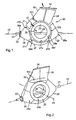
- the figure 1 is a schematic side view of a tool having a segmented mandrel used for the manufacture of a helicopter tailpiece as illustrated figure 6 by a manufacturing method according to a first embodiment of the invention.
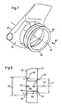
- the figure 7 illustrates, in schematic perspective view, the establishment of a vein conduit in a helicopter tailpiece according to the invention, for the mutual attachment of the two parts.
- the figure 8 is a partial sectional view, along a section plane containing the axis of the air vein duct, of the assembly of this duct with the two opposite side walls of a tail piece according to the invention.
- the Figures 9 to 11 relate to a second embodiment of the invention.
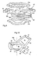
- the figure 9 illustrates, in schematic perspective view, a tool for assembling two preforms such as those illustrated figure 11 .
- the figure 10 illustrates, in schematic perspective view, a preform designed to form the left part of a tail structure according to the invention.
- the figure 11 illustrates, with substantially the same direction of observation as for the figure 10 , two substantially symmetrical preforms placed opposite one another.
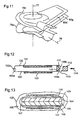
- the figure 12 schematically illustrates, in cross-sectional view, a tool for manufacturing a thermoplastic shell by simultaneously consolidating portions of two overlapping preforms.
- the figure 13 illustrates schematically, in cross-sectional view, a tool for manufacturing a tail structure from a preform supported by a mandrel, by plating - under the effect of a depression - a flexible envelope enclosing the preform .
- the terms “left” and “right” are used by reference to an observer looking at the helicopter tail structure and / or the helicopter, from the rear of the (this one); the terms “forward” and “rear” are used by reference to the normal direction of advance of the helicopter.
- the device for molding a composite fairing structure comprises a core or mandrel 20 that can be reversibly secured to a shaft 21 having a longitudinal axis 22.
- the mandrel comprises an annular central piece 23 having substantially a shape of revolution of axis 24; the part 23 is pierced with two aligned orifices 25, through which the shaft 21 extends.
- the mandrel further comprises six sectors or segments 26 to 31 mandrel, which are arranged around the part 23 they encircle.
- the number of parts constituting the mandrel, the geometry and the arrangement of these parts may vary depending on the geometric, mechanical and thermal constraints specific to each embodiment.
- Each of these sectors - in particular sector 27 or 28 - has a concave internal support face - in particular the faces 27a of sector 27 and 28a of sector 28 - which is likely to be placed in close contact and / or marry a corresponding portion of the outer convex surface 23b of the piece 23.
- the inner faces such as 27a, 28a of the sectors 26 to 31 are in the form of a portion cylinder, of the same radius, the meeting of these internal faces substantially covering the entirety of the surface 23b; this corresponds to an assembly configuration of the sectors (26 to 31) to the central ring 23; the illustrated configuration figure 1 is different, since the sectors have been shown in spaced position relative to the part 23, to improve the understanding of the structure of the mandrel.
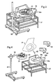
- the sectors are made integral with the ring 23 by conventional connecting means not shown; in this configuration, two adjacent sectors are substantially in contact with one of their respective end faces - such as 260 and 271 for sectors 26 and 27, or such as 270 and 281 for sectors 27 and 28 -; in addition, the (outer) side faces - such as the face 26d of the sector 26 and the face 30d of the sector 30 - of two adjacent sectors are tangent along their mutually opposite edges, and tangential to the lateral surface 23d of the 23, so as to form a smooth lateral surface for receiving the prepreg, in the illustrated configuration figure 2 wherein the sectors of the mandrel have been placed in contact with the ring 23 and secured thereto.
- the shaft 21 allowing the rotation of the mandrel 20 along the axis 22, extends through the two sectors 26 and 28 of the mandrel, through a front face 26e of the sector 26 and a rear face 28e of the sector 28 .
- the tooling further comprises a piece 33 in the form of a disc, and a piece 34 shaped profiled blade; the piece 33 is pierced with an opening allowing the passage of the shaft 21; the piece 33 is secured to the front face 26 of the sector 26 with which it forms a male mold portion for a prepreg portion of the preform which constitutes a connecting portion of the tail composite structure with the rear portion (or beam tail) of the fuselage of a helicopter.
- the piece 34 is secured to the upper end of the sectors 29 and 30 to form a male mold part for a portion of the preform intended to form a drift portion of the final composite structure.
- the latter is rotatably mounted (or oscillating) on the frame of a machine of automatic placement of prepreg, which places one or more layer (s) of fibers or fabrics impregnated with resin, on the outer surface of the mandrel, which applies pressure - using a roller or pressure roller - on the deposited fibers or fabrics, and which cuts these fibers or fabrics to the desired length; these operations are carried out under the control of a computer of the machine, according to a specific program and data relating to the geometry of the part to be obtained, and the number and orientation of the different fiber sections or strips prepreg used to make the preform.
- At least a portion of the preform corresponding to the side walls of the structure to be obtained has a honeycomb core which is shaped and pressed between two prepreg skins.
- the shaft 21 is separated from the mandrel and the latter - supporting the preform 35 - is placed in a recessed half mold 36a of a shape adapted to that of the outer half-face of the part to be obtained; for this purpose, as illustrated figure 3 , the half-mold 36a is placed on a support 37, while the mandrel is supported by an arm 38 of a manipulator 39, the arm 38 being temporarily secured to the ring 23 of the mandrel by means of a triangulated structure 40 .
- a second mold half 36b pierced with a lateral opening 36c is then secured to the mold half 36a with which it envelops the preform; the mandrel is then extracted from the preform, by a lateral opening provided in a lateral face of the preform and by the opening 36c provided in the wall of the half-mold 36b, and which extends substantially opposite the lateral opening of the preform; for this purpose, the ring 23 is detached from the segments and extracted from the mold 36a, 36b, being held suspended from the arm 38 of the manipulator 39.
- a first segment - such as segment 31 figure 1 - is then moved along the arrow 32 in the direction of the axis 24 to come opposite said openings and be extracted from the mold by them; the other segments 26 to 30 are then successively extracted, starting preferably with one of the segments (26 or 30) adjacent to the previously extracted segment 31, and so on.
- the end faces of the segments other than the segment 31 - such as the faces 270 and 271 for the segment 27 - extend substantially radially with respect to the axis 24 which substantially corresponds to the axis passing through the center of said openings; the end faces 310 and 311 of the segment 31 extend in cons substantially parallel to each other and parallel to the arrow 32 directed towards the axis 24.
- a wall 41 or deformable support bladder of the preform is then inserted (according to the arrow 42 figure 4 ) in this cavity, and is placed in contact with the inner face of the preform to support it during subsequent operations of the method.
- the bladder may be inflated by a gas - such as air - under pressure; alternatively, a depression may be created in the mold 36a, 36b to press the walls of the skin or bladder 41 against the inner face of the hollow preform housed in the mold.
- a gas - such as air - under pressure
- the mold containing the preform and the preform support structure are then placed in an autoclave or oven to cure the prepreg resin in the preform.
- the two half-molds 36a and 36b are separated from one another and the part according to the invention is extracted from this mold, as illustrated. figure 5 .
- the helicopter tail structure 43 thus obtained is approximately symmetrical with respect to an anteroposterior plane 56; the structure comprises a first lateral wall 45 pierced with a circular opening 46 whose center is situated on a transverse axis 57 substantially orthogonal to the plane 56; the structure 43 comprises a second lateral wall 47 pierced with a circular opening 48 whose center is also located on the axis 57.
- the wall 45 is extended upwards by a wall 52 forming a left wall drift 51, while the wall 47 is extended upwardly by a wall 53 forming a right wall drift.
- the front portions (or front portions) of the walls 52 and 53 join along a frontal zone 60, and the front portions of the walls 45 and 47 join to form a frontal zone 55a, 55b whose upper portion 55a extends the zone 60.
- a portion 44a, 44b connecting the tail structure to the fuselage of the helicopter comprises a short cylindrical portion 44a extending along an axis 58 contained in the plane 56, and a flat portion 44b in the form of an axis disk 58, which is surrounded by the portion 44a.
- the lower portions of the walls 45 and 47 meet to form a lower zone 49 pierced with an opening 50, while the rear portions of these walls 45, 47 form a rear joining zone 62 which is pierced by an opening 59.
- junction areas 49, 54, 55a and 55b, 60 to 62 form with the side walls 45, 47, 52, 53 and with the connecting structure 44a, 44b, a rigid one-piece and lightweight hollow structure.
- This structure 43 is then assembled with a duct 63, as illustrated Figures 7 and 8 , to form a helicopter tail rotor fairing.
- the conduit 63 which is made of a composite material as well, comprises a substantially cylindrical central portion 64 (of substantially constant radius) along the axis 57.
- a diverging portion 69 terminated by a second circular flange 70 parallel to the first flange 66 and having an outside diameter 71 smaller than the outside diameter 72 of the flange 66.
- downstream portion of the duct 63 is introduced inside the structure 43, through the opening 46 formed in the side wall 45, according to the arrow 67, until the small diameter flange 70 comes in contact with the inner face of the wall 47, around the opening 48 provided in this wall.
- the flange 66 of larger diameter is in contact with the outer face of the wall 45, around the opening 46 provided therein; in this position, the parts 63 and 43 are assembled (by gluing, riveting, solidification of the organic matrix) flange portions of the duct 63 covering the corresponding portions of the side walls of the part 43.
- the overall preform is made from two substantially symmetrical preforms 76g and 76d illustrated figure 11 .
- the left preform 76g illustrated figure 10 has a substantially circular central portion 90 extending perpendicular to an axis 77 passing through its center; a portion of lateral preform 80 extends around the central portion 90; a portion 82 of connection with the fuselage extends from the portion 80; the portion 82 has substantially the shape of a frustoconical half-cap axis 78 parallel to the plane of the portion 90; a drift left wall preform portion 81 also extends from the portion 80.
- Each of the portions 80, 81, 82 prepreg preform is extended at its periphery by a prepreg strip, these strips being respectively marked 83 to 89.
- Tooling illustrated figure 9 further comprises three flattened pieces 95 to 97; these parts serve to seal between the respective end faces 92a, 92b and 92c of the flexible core 92 supporting the preform in the mold, with the corresponding peripheral walls of the mold 91d, 91g; they also make it possible to ensure a mechanical connection between the two half-molds.
- the piece obtained is similar to that illustrated figure 6 ; it is observed in this figure that the part 43 has a complex shape, flattened along the axis 57, and elongate in a direction of the plane 56 which is close to the respective directions of the leading and trailing edges of the drift portion; this piece has respective concave portions for connecting the lateral portions 45, 47 with the lateral portions 52 and 53; the side portions 45, 47 of fairing are largely hollowed out.
- thermoplastic preform 100 is supported by a holding tool 101, and a second thermoplastic half-preform 102 is supported by another tool 103 for holding the preform.
- a peripheral portion (or edge) 102a of the preform 102 covers a peripheral portion 100a of the preform 100; symmetrically, an edge 100b of the preform 100 covers an edge 102b of the preform 102.
- a male forming tool 110 extends between the preforms 100 and 102, a portion 111 disposed opposite the edges 100b and 102b to be secured to the shape of the inner face of the part to be produced, in the junction area of the edges. 100b, 102b.
- a female forming tool 112 extends outside the preforms; a portion 113 of the tool 112 is disposed opposite superimposed edges 100b, 102b, which matches the shape of the outer face of the part to be produced, in this junction area.
- the joining of the edges 100b, 102b is obtained by moving the tool 112 along the arrow 114 in the direction of the tool 110, to compress the edges between the faces 111 and 113 of the tools 110, 112.
- This operation may require the softening of the edges by heating; it allows the fusion bonding of the resin edges, then cooling of this resin.
- the preform 100 is supported by a mandrel in two parts 104, 105 which it marries the outer surface 106.
- Means for depressing the interstitial space 107 separating the mandrel from the preform and / or the interstitial space 108 separating the preform from the envelope 109 enable the formers to be pressed against the external surface of the preform. the envelope parts.
- a tight bag or envelope 109 surrounds the preform 100 and anti-wrinkle conformers 120, 121 interposed between the preform and the envelope; the inner face 123, 124 of the conformers 120, 121 is adapted to the shape of corresponding parts of the outer face of the part obtained by stiffening the preform 100.
Landscapes
- Engineering & Computer Science (AREA)
- Mechanical Engineering (AREA)
- Aviation & Aerospace Engineering (AREA)
- Manufacturing & Machinery (AREA)
- Chemical & Material Sciences (AREA)
- Composite Materials (AREA)
- Transportation (AREA)
- Moulding By Coating Moulds (AREA)
- Casting Or Compression Moulding Of Plastics Or The Like (AREA)
Applications Claiming Priority (1)
| Application Number | Priority Date | Filing Date | Title |
|---|---|---|---|
| FR0413397A FR2879496B1 (fr) | 2004-12-16 | 2004-12-16 | Procede et dispositif de fabrication d'une carene de rotor d'helicoptere, et carene obtenue |
Publications (2)
| Publication Number | Publication Date |
|---|---|
| EP1676775A1 EP1676775A1 (fr) | 2006-07-05 |
| EP1676775B1 true EP1676775B1 (fr) | 2015-11-18 |
Family
ID=34951807
Family Applications (1)
| Application Number | Title | Priority Date | Filing Date |
|---|---|---|---|
| EP05026158.5A Expired - Fee Related EP1676775B1 (fr) | 2004-12-16 | 2005-12-01 | Procédé et dispositif de fabrication d'une carène de rotor d'hélicoptère, et carène obtenue |
Country Status (5)
| Country | Link |
|---|---|
| US (1) | US7676923B2 (ja) |
| EP (1) | EP1676775B1 (ja) |
| JP (1) | JP4236661B2 (ja) |
| CN (1) | CN100410144C (ja) |
| FR (1) | FR2879496B1 (ja) |
Families Citing this family (21)
| Publication number | Priority date | Publication date | Assignee | Title |
|---|---|---|---|---|
| FR2924378B1 (fr) * | 2007-03-29 | 2010-01-01 | Carbone Forge | Procede de fabrication par moulage d'une piece composite thermoplastique. |
| DE102007015909A1 (de) * | 2007-04-02 | 2008-10-09 | Mt Aerospace Ag | Verfahren zur Herstellung faserverstärkter Hohlkörper |
| GB2470087B (en) * | 2007-06-07 | 2010-12-29 | Gkn Aerospace Services Ltd | Mandrel for use in a method of making composite flange |
| US8936695B2 (en) * | 2007-07-28 | 2015-01-20 | The Boeing Company | Method for forming and applying composite layups having complex geometries |
| US20100279806A1 (en) * | 2008-01-03 | 2010-11-04 | Aling Lai | Transmission structure improvement for bending tail pipe |
| CN102019592B (zh) * | 2009-09-10 | 2012-07-04 | 中国航空工业集团公司北京航空制造工程研究所 | 一种大尺寸复合材料加筋壁板成形的定位装置 |
| CN101791821B (zh) * | 2010-04-08 | 2011-09-14 | 中国航空工业集团公司北京航空制造工程研究所 | 一种大尺寸复合材料长桁的成形装置 |
| US20120104153A1 (en) * | 2010-11-02 | 2012-05-03 | Groen Brothers Aviation, Inc | Gyroplane prerotation by compressed air |
| FR2968272B1 (fr) * | 2010-12-06 | 2013-07-12 | Eurocopter France | Element de structure ameliore d'un giravion pour diminuer la trainee aerodynamique. |
| ITRM20110626A1 (it) * | 2011-11-25 | 2013-05-26 | Aeronautical Service S R L | Metodo per la realizzazione di supporti di sostegno per l'avionica. |
| EP2706009B1 (en) | 2012-09-07 | 2016-04-27 | AIRBUS HELICOPTERS DEUTSCHLAND GmbH | An empennage of a helicopter |
| US9889613B2 (en) | 2012-11-01 | 2018-02-13 | Israel Aerospace Industries Ltd. | Manufacture of integrated structures formed of composite materials |
| US8983171B2 (en) | 2012-12-26 | 2015-03-17 | Israel Aerospace Industries Ltd. | System and method for inspecting structures formed of composite materials during the fabrication thereof |
| EP2878433B1 (en) * | 2013-11-29 | 2016-04-20 | AIRBUS HELICOPTERS DEUTSCHLAND GmbH | Shrouded rotary assembly from segmented composite for aircraft and method for its manufacture |
| PL3061689T3 (pl) * | 2015-02-27 | 2018-01-31 | Airbus Helicopters Deutschland GmbH | Zespół ogonowy do wiropłatu, wiropłat i sposób wytwarzania wzmocnionego zespołu ogonowego |
| EP3199455B1 (en) * | 2016-01-29 | 2020-04-22 | AIRBUS HELICOPTERS DEUTSCHLAND GmbH | Rotary aircraft with an interface frame joining the fuselage tail boom and the tail cone |
| US10814971B2 (en) * | 2018-04-10 | 2020-10-27 | Textron Innovations Inc. | Tail rotor housing |
| CN109130247B (zh) * | 2018-07-20 | 2021-02-26 | 菲舍尔航空部件(镇江)有限公司 | 航空复材c型盒体零件成型方法 |
| KR102215966B1 (ko) * | 2019-08-21 | 2021-02-16 | 한국항공우주산업 주식회사 | 헬리콥터용 에프터 콘 핀 제조 장치 |
| US20220315212A1 (en) * | 2021-04-06 | 2022-10-06 | Bell Textron Inc. | Distributed propulsion structure |
| CN113977984B (zh) * | 2021-10-15 | 2023-07-04 | 江西洪都航空工业集团有限责任公司 | 一种管状双曲面复合材料结构件的制备方法 |
Family Cites Families (16)
| Publication number | Priority date | Publication date | Assignee | Title |
|---|---|---|---|---|
| FR2542695B1 (fr) * | 1983-03-18 | 1985-07-26 | Aerospatiale | Helice multipale a pas variable a pale s en materiaux composites demontables individuellement, procede de fabrication de telles pales et pales ainsi realisees |
| FR2556650B1 (fr) * | 1983-12-14 | 1986-05-23 | Matra | Procede et dispositif de fabrication de corps structural creux en materiau composite, notamment pour missiles |
| US4594761A (en) * | 1984-02-13 | 1986-06-17 | General Electric Company | Method of fabricating hollow composite airfoils |
| US4986949A (en) * | 1986-05-12 | 1991-01-22 | Trimble Brent J | Method of making composite bicycle frames |
| FR2683504A1 (fr) * | 1991-11-07 | 1993-05-14 | Aerospatiale | Systeme anticouple a rotor arriere pour helicoptere. |
| FR2699498B1 (fr) * | 1992-12-23 | 1995-03-10 | Eurocopter France | Pale en composite thermoplastique, notamment pour rotor arrière caréné d'hélicoptère, et son procédé de fabrication. |
| FR2719553B1 (fr) * | 1994-05-04 | 1996-07-26 | Eurocopter France | Dispositif anti-couple à rotor arrière et stator redresseur carénés pour hélicoptère. |
| WO1996009159A1 (en) * | 1994-09-20 | 1996-03-28 | Viatech, Inc. | Method of making internally reinforced composite tubes |
| FR2740380B1 (fr) * | 1995-10-30 | 1998-01-02 | Eurocopter France | Procede de fabrication d'une pale a pas variable en materiau composite pour rotor d'helicoptere |
| FR2740378B1 (fr) * | 1995-10-30 | 1998-01-02 | Eurocopter France | Procede de fabrication d'une pale a pas variable en materiau composite pour rotor d'helicoptere, et pale a pas variable pouvant etre obtenue par un tel procede |
| FR2766407B1 (fr) * | 1997-07-22 | 1999-10-15 | Aerospatiale | Procede de fabrication de pieces de grandes dimensions en materiau composite a matrice thermoplastique, telles que des troncons de fuselage d'aeronefs |
| US6372176B1 (en) * | 1999-03-01 | 2002-04-16 | Kiefel Technologies Inc. | System and method for twin sheet forming |
| US6889937B2 (en) * | 1999-11-18 | 2005-05-10 | Rocky Mountain Composites, Inc. | Single piece co-cure composite wing |
| DE10153875A1 (de) * | 2001-11-02 | 2003-05-15 | Bpw Bergische Achsen Kg | Bauteil in langgestreckter Bauweise aus einem Faser-Kunststoff-Verbund |
| US7204951B2 (en) * | 2002-07-30 | 2007-04-17 | Rocky Mountain Composites, Inc. | Method of assembling a single piece co-cured structure |
| EP1473131A3 (de) * | 2003-04-30 | 2007-01-03 | Airbus Deutschland GmbH | Verfahren zum herstellen textiler vorformlinge aus textilen halbzeugen |
-
2004
- 2004-12-16 FR FR0413397A patent/FR2879496B1/fr not_active Expired - Fee Related
-
2005
- 2005-12-01 EP EP05026158.5A patent/EP1676775B1/fr not_active Expired - Fee Related
- 2005-12-07 US US11/295,523 patent/US7676923B2/en active Active
- 2005-12-07 JP JP2005353122A patent/JP4236661B2/ja not_active Expired - Fee Related
- 2005-12-16 CN CNB2005101320192A patent/CN100410144C/zh not_active Expired - Fee Related
Also Published As
| Publication number | Publication date |
|---|---|
| CN1810577A (zh) | 2006-08-02 |
| US7676923B2 (en) | 2010-03-16 |
| CN100410144C (zh) | 2008-08-13 |
| US20060169835A1 (en) | 2006-08-03 |
| FR2879496B1 (fr) | 2008-12-12 |
| JP2006168718A (ja) | 2006-06-29 |
| JP4236661B2 (ja) | 2009-03-11 |
| FR2879496A1 (fr) | 2006-06-23 |
| EP1676775A1 (fr) | 2006-07-05 |
Similar Documents
| Publication | Publication Date | Title |
|---|---|---|
| EP1676775B1 (fr) | Procédé et dispositif de fabrication d'une carène de rotor d'hélicoptère, et carène obtenue | |
| EP0603066B1 (fr) | Procédé de fabrication de liaisons en matériau composite de structures en forme de treillis ou d'éléments de treillis, et treillis obtenus par ce procédé | |
| EP0686554B1 (fr) | Aube de redresseur en composite, redresseur la comportant, pour dispositif anti-couple à rotor et stator redresseur carénés, et leur procédé de fabrication | |
| EP0296014B1 (fr) | Pale en matériaux composites et son procédé de fabrication | |
| EP2407319B1 (fr) | Jante ou portion de jante réalisée en matériau composite | |
| EP0585144B1 (fr) | Procédé et dispositif de moulage de pièce en matériau composite constituée de deux secteurs | |
| EP0346210A1 (fr) | Cadre en matériau composite notamment pour fuselage d'aéronef, et son procédé de fabrication | |
| FR3012362A1 (ja) | ||
| FR2740380A1 (fr) | Procede de fabrication d'une pale a pas variable en materiau composite pour rotor d'helicoptere | |
| FR3024389A1 (fr) | Procede de fabrication d'une piece renforcee comportant un materiau composite | |
| EP2419262B1 (fr) | Procede de fabrication d'une bielle en materiau composite ayant des extremites renforcees | |
| CA2875489A1 (fr) | Procede de fabrication de panneaux cellulaires, destines notamment au domaine de l'aeronautique | |
| EP3466657A1 (fr) | Procédé de fabrication de carter composite de compresseur pour turbomachine | |
| EP2846987A1 (fr) | Procédé de fabrication d'une peau en composite formant virole non démoulable | |
| FR2740379A1 (fr) | Procede de fabrication d'une pale en materiau composite pour rotor d'helicoptere, et pale pouvant etre obtenue par un tel procede | |
| EP2804745B1 (fr) | Procédé pour la fabrication d'une pièce composite par drapage | |
| EP4098860B1 (fr) | Lame pour inverseur de poussee et un procede de fabrication d'une telle lame | |
| FR2556650A1 (fr) | Procede et dispositif de fabrication de corps structural creux en materiau composite, notamment pour missiles | |
| FR3061070A1 (fr) | Procede de realisation d’un panneau auto raidi en materiaux composites et panneau obtenu par ledit procede | |
| WO2013107993A2 (fr) | Ensemble d'outillage et procédé de fabrication d'une pièce en matériau composite |
Legal Events
| Date | Code | Title | Description |
|---|---|---|---|
| PUAI | Public reference made under article 153(3) epc to a published international application that has entered the european phase |
Free format text: ORIGINAL CODE: 0009012 |
|
| AK | Designated contracting states |
Kind code of ref document: A1 Designated state(s): AT BE BG CH CY CZ DE DK EE ES FI FR GB GR HU IE IS IT LI LT LU LV MC NL PL PT RO SE SI SK TR |
|
| AX | Request for extension of the european patent |
Extension state: AL BA HR MK YU |
|
| 17P | Request for examination filed |
Effective date: 20061115 |
|
| AKX | Designation fees paid |
Designated state(s): GB IT |
|
| REG | Reference to a national code |
Ref country code: DE Ref legal event code: 8566 |
|
| 17Q | First examination report despatched |
Effective date: 20110218 |
|
| RAP1 | Party data changed (applicant data changed or rights of an application transferred) |
Owner name: AIRBUS HELICOPTERS |
|
| REG | Reference to a national code |
Ref country code: DE Ref legal event code: R079 Free format text: PREVIOUS MAIN CLASS: B64C0027040000 Ipc: B29C0033480000 |
|
| GRAP | Despatch of communication of intention to grant a patent |
Free format text: ORIGINAL CODE: EPIDOSNIGR1 |
|
| RIC1 | Information provided on ipc code assigned before grant |
Ipc: B29L 31/08 20060101ALN20150605BHEP Ipc: B29L 31/30 20060101ALN20150605BHEP Ipc: B29C 70/30 20060101ALI20150605BHEP Ipc: B29C 70/34 20060101ALI20150605BHEP Ipc: B64C 27/82 20060101ALI20150605BHEP Ipc: B29C 33/48 20060101AFI20150605BHEP Ipc: B64C 27/04 20060101ALI20150605BHEP Ipc: B64F 5/00 20060101ALN20150605BHEP Ipc: B29B 11/16 20060101ALI20150605BHEP |
|
| INTG | Intention to grant announced |
Effective date: 20150624 |
|
| GRAS | Grant fee paid |
Free format text: ORIGINAL CODE: EPIDOSNIGR3 |
|
| GRAA | (expected) grant |
Free format text: ORIGINAL CODE: 0009210 |
|
| AK | Designated contracting states |
Kind code of ref document: B1 Designated state(s): GB IT |
|
| REG | Reference to a national code |
Ref country code: GB Ref legal event code: FG4D Free format text: NOT ENGLISH |
|
| PLBE | No opposition filed within time limit |
Free format text: ORIGINAL CODE: 0009261 |
|
| STAA | Information on the status of an ep patent application or granted ep patent |
Free format text: STATUS: NO OPPOSITION FILED WITHIN TIME LIMIT |
|
| 26N | No opposition filed |
Effective date: 20160819 |
|
| PGFP | Annual fee paid to national office [announced via postgrant information from national office to epo] |
Ref country code: GB Payment date: 20201223 Year of fee payment: 16 |
|
| PGFP | Annual fee paid to national office [announced via postgrant information from national office to epo] |
Ref country code: IT Payment date: 20201224 Year of fee payment: 16 |
|
| GBPC | Gb: european patent ceased through non-payment of renewal fee |
Effective date: 20211201 |
|
| PG25 | Lapsed in a contracting state [announced via postgrant information from national office to epo] |
Ref country code: GB Free format text: LAPSE BECAUSE OF NON-PAYMENT OF DUE FEES Effective date: 20211201 |
|
| PG25 | Lapsed in a contracting state [announced via postgrant information from national office to epo] |
Ref country code: IT Free format text: LAPSE BECAUSE OF NON-PAYMENT OF DUE FEES Effective date: 20211201 |