EP1674307B1 - Axle suspension apparatus - Google Patents
Axle suspension apparatus Download PDFInfo
- Publication number
- EP1674307B1 EP1674307B1 EP05026759A EP05026759A EP1674307B1 EP 1674307 B1 EP1674307 B1 EP 1674307B1 EP 05026759 A EP05026759 A EP 05026759A EP 05026759 A EP05026759 A EP 05026759A EP 1674307 B1 EP1674307 B1 EP 1674307B1
- Authority
- EP
- European Patent Office
- Prior art keywords
- suspension apparatus
- torsion
- axle suspension
- trailing arms
- arms
- Prior art date
- Legal status (The legal status is an assumption and is not a legal conclusion. Google has not performed a legal analysis and makes no representation as to the accuracy of the status listed.)
- Expired - Fee Related
Links
Images


Classifications
-
- B—PERFORMING OPERATIONS; TRANSPORTING
- B60—VEHICLES IN GENERAL
- B60G—VEHICLE SUSPENSION ARRANGEMENTS
- B60G21/00—Interconnection systems for two or more resiliently-suspended wheels, e.g. for stabilising a vehicle body with respect to acceleration, deceleration or centrifugal forces
- B60G21/02—Interconnection systems for two or more resiliently-suspended wheels, e.g. for stabilising a vehicle body with respect to acceleration, deceleration or centrifugal forces permanently interconnected
- B60G21/04—Interconnection systems for two or more resiliently-suspended wheels, e.g. for stabilising a vehicle body with respect to acceleration, deceleration or centrifugal forces permanently interconnected mechanically
- B60G21/05—Interconnection systems for two or more resiliently-suspended wheels, e.g. for stabilising a vehicle body with respect to acceleration, deceleration or centrifugal forces permanently interconnected mechanically between wheels on the same axle but on different sides of the vehicle, i.e. the left and right wheel suspensions being interconnected
- B60G21/051—Trailing arm twist beam axles
-
- B—PERFORMING OPERATIONS; TRANSPORTING
- B60—VEHICLES IN GENERAL
- B60G—VEHICLE SUSPENSION ARRANGEMENTS
- B60G2202/00—Indexing codes relating to the type of spring, damper or actuator
- B60G2202/10—Type of spring
- B60G2202/13—Torsion spring
- B60G2202/136—Twist-beam type arrangement
- B60G2202/1362—Twist-beam type arrangement including a second torsional element, e.g. second beam, stabiliser bar or tube
-
- B—PERFORMING OPERATIONS; TRANSPORTING
- B60—VEHICLES IN GENERAL
- B60G—VEHICLE SUSPENSION ARRANGEMENTS
- B60G2204/00—Indexing codes related to suspensions per se or to auxiliary parts
- B60G2204/10—Mounting of suspension elements
- B60G2204/12—Mounting of springs or dampers
- B60G2204/122—Mounting of torsion springs
- B60G2204/1226—Mounting of torsion springs on the trailing arms of a twist beam type arrangement
-
- B—PERFORMING OPERATIONS; TRANSPORTING
- B60—VEHICLES IN GENERAL
- B60G—VEHICLE SUSPENSION ARRANGEMENTS
- B60G2206/00—Indexing codes related to the manufacturing of suspensions: constructional features, the materials used, procedures or tools
- B60G2206/01—Constructional features of suspension elements, e.g. arms, dampers, springs
- B60G2206/20—Constructional features of semi-rigid axles, e.g. twist beam type axles
- B60G2206/201—Constructional features of semi-rigid axles, e.g. twist beam type axles with detachable cross beam and/or torsion stabiliser bar/tube
Definitions
- the present invention generally relates to suspensions of vehicles and, more particularly, to an axle suspension apparatus of a vehicle.
- the suspensions of vehicles there are various kinds of the suspensions of vehicles so that an appropriate kind of suspension is selected and used in accordance with requirements of drivability, a ride comfort characteristic or a vibration characteristic of vehicles.
- a torsion beam type suspension having a trailing arm and a torsion beam connected to the trailing arm by welding.
- the torsion beam type suspension is widely used as an axle suspension apparatus of rear wheels of small or middle size automobiles.
- torsion beam type suspension it is required for the torsion beam to have rigidity with respect to a side force applied when turning or a torsion force applied when running over an unevenness of a road surface. Accordingly, when designing the torsion beam type suspension, it is required to sufficiently consider a balance between rigidity and flexibility of structural components.
- Japanese Laid-Open Patent Application No. 2003-525158 discloses a torsion beam type suspension that generates a torque in response to torsion by using an elastic member and also provides flexibility.
- Japanese Laid-Open Patent Application No. 11-198623 shows a suspension system comprising trailing arms, wherein each front end of the trailing arms is rotatably connected to an end of a beam and the rear wheels are attached to the rear end of each trailing arm.
- the suspension system of EP 122 891 A1 shows a beam that is connected to respective trailing arms by interposing a sleeve of elastomeric material there between such that the beam is subject to bending only, since any torsion is absorbed by deformation of the elastomeric material.
- US 4,434,998 shows a rear wheel suspension including trailing arms that are pivoted at their forward end on the body and carry wheels at their rearward end, wherein beam is connected to each trailing arm between the body pivot and the wheel axis.
- the connection of the beam and the trailing arm permit a relative rotation between each control arm and the respective connected end of the beam along an axis which extends obliquely to the trailing arm.
- JP 2001-039136 shows a similar arrangement.
- a position of a shear center of the torsion beam gives a considerable influence to an alignment change, and determines a performance and characteristic of the suspension.
- a connecting position between the torsion beam and the trailing arm since there is a physical limitation such as a vehicle body shape, an arm shape or a beam bending shape, it is not easy to change the connecting position between the torsion beam and the trailing arm to match a design target of alignment.
- a more specific object of the present invention is to provide an axle suspension apparatus which has a large freedom of design to permit setting of an optimum alignment change.
- an axle suspension apparatus comprising: a pair of left and right arms each having a vehicle support part supported on a vehicle body and a wheel support part supporting a wheel; and a beam provided between said left and right arms, both ends of the beam being rotatably connected to the respective left and right arms between the vehicle body support part and the wheel support part of each arm, wherein rotation axes of the both ends of said beam are at angles with respect to a line connecting the both ends of said beam and a middle part of the beam extends along a line connecting the vehicle support parts supported on said vehicle body.
- an optimum alignment change can be set easily by adjusting the orientation of the rotation axes of both ends of the beam. There is no need to change the connecting positions between the beam and the arms and the shape of the beam in accordance with a design target of the alignment, a freedom of design is increased.
- a middle part of said beam extends along a line connecting said parts supported on said vehicle body. That is, the beam may be bent so that a middle part of the beam extends along a line connecting the parts supported on the vehicle body. Accordingly, the middle part of the beam does not swing up and down even at the time of the same phase stroke or opposite phase stroke of the left and right wheels. Thus, there is no need to reserve a space to permit the movement of the middle part of the beam, and a freedom of design in the positional relationship with surrounding components of the vehicle is increased.
- the axle suspension apparatus may further comprise a stabilizer bridged between said left and right arms.
- the stabilizer increases torsion rigidity of the suspension at the time of opposite phase stroke.
- the axle suspension apparatus may further comprise a bush provided between each end of said beam and a respective one of said left and right arms, the bush including an elastic member that roatatably connects each end of said beam to the respective one of said left and right arms. Accordingly, the beam can rotate freely at the connecting part to the arms due to the bush interposed between the beam and the arms, and a shock from a road surface can be absorbed by the elastic material constituting the bush.
- the axle suspension apparatus may further comprise a bearing provided between each end of said beam and a respective one of said left and right arms, the bearing roatatably connecting each end of said beam to the respective one of said left and right arms. Accordingly, the beam can rotate freely at the connecting part to the arms due to the bearing interposed between the beam and the arms.
- an orientation of the rotation axes of the both ends of said beam may be set in accordance with a target alignment change.
- a target alignment change such as a can be change or a toe change due to a shock or a vibration transmitted from a road surface
- the orientation of the axes of both ends of the beam is adjusted so that an optimum suspension mechanism can be designed easily.
- said beam may be bent so as to avoid said beam from interfering with components surrounding said beam.
- Setting of an optimum alignment change does not depend on the shape of the beam but depends on the orientation of the rotation axes of both ends of the beam.
- FIG. 1 is a plan view of a torsion beam type suspension provided in a vehicle.
- FIG. 2 is a side view of the torsion beam type suspension shown in FIG. 3.
- the torsion beam type suspension includes left and right trailing arms 160L and 160R extending in a longitudinal direction of the vehicle.
- Bushes 162L and 162R having elastic members are coupled to front ends of the left and right trailing arms 160L and 160R, respectively, so as to be swingably supported on a vehicle body.
- axle bearings are attached to rear ends of the left and right trailing arms 160A and 160R so as to rotatably support the wheels 100L and 100R, respectively.
- shock absorbers 110L and 110R and coil springs 112L and 112R are attached to the left and right trailing arms 160L and 160R in the vicinity of the rear ends thereof, respectively.
- a torsion beam 150 is provided between the left and right trailing arms 160L and 160R so as to connect middle portions of the left and right trailing arms 160L and 160R. Left and right ends of the torsion beam 150 are welded to the left and right trailing arms 160L and 160R, respectively.
- the left and right wheels vibrates up and down. If the unevenness on the road surface is in the same phase on the left and right sides, the left and right wheels vibrate in the same phase. If the unevenness on the road surface is in opposite phase on the left and right sides, the left and right wheels vibrate up and down in opposite phase. Additionally, even when the vehicle is running on a flat road surface, the vehicle body rolls due to a centrifugal force when the vehicle turns, which causes the left and right wheels to vibrate up and down in opposite phase.
- the above-mentioned up and down vibration of the wheels are transmitted to the left and right trailing arms 160L and 160R. If they are the same phase stroke, the left and right trailing arms 160L and 160R and the torsion beam 150 entirely swing about a line connecting the bushes 162L and 162R on the front ends of the left and right trailing arms 160L and 160R, and shocks are absorbed by the coil springs 112L and 112R and the shock absorbers 110L and 110R.
- the left and right trailing arms 160L and 160R move in opposite directions each other, which causes a torsion in the torsion beam 150.
- a counter force to return the torsion is generated so as to prevent the vehicle from rolling.
- a position of a shear center of the torsion beam which gives a considerable influence to an alignment change, is an important index.
- a point B immediately in front of the torsion beam 150 in the middle of the torsion beam 150 is the shear center.
- the performance and characteristic of the suspension remarkably changes in accordance with the position of the shear center B.
- the shear center B of the torsion beam 150 is set to a point A, which is behind the point B, so as to achieve an optimum alignment change, it may be difficult to displace the torsion beam 150 rearward depending on a positional relationship with a spare-tire house 102 or a muffler 104.
- the shear center B of the torsion beam 150 is set to a point, which is ahead of the point B, it may be difficult to displace the torsion beam 150 due to a relationship with a fuel tank 108.
- an exhaust pipe 106 or the like may be an obstacle to the displacement of the torsion beam 150.
- the left and right trailing arms 160L and 160R swing about a rotational axis connecting the left and right bushes 162L and 160R as indicated by arrows in FIG. 1.
- the torsion beam 150 moves up and down. Accordingly, it is necessary to consider the arrangement to maintain a space between the torsion beam 150 and the exhaust pipe 106 by bending the exhaust pipe 106 upward so that the torsion beam 150 does not contact with the exhaust pipe 106 even when the torsion beam 105 moves up and down.
- the torsion beam 150 there are various components around the torsion beam 150, such as the spare-tire house 102, the muffler 104, the exhaust pipe 106, the fuel tank 108, etc, and there may be a physical limitation given by those components when determining arrangement and configuration of the torsion beam 150. Thus, there may be a case where it is difficult to achieve an ideal alignment change. Additionally, there may occur a situation where arrangement and configuration of the surrounding components must be changed to achieve an optimum alignment change.
- FIG. 3 is a perspective view showing a structure of an axle suspension apparatus according to a background art of the present invention.
- a pair of left and right trailing arms 20L and 20R extend separately in a longitudinal direction of the vehicle.
- a beam 10 extends in a direction of width of the vehicle and is bridged between the left and right trailing arms 20L and 20R so as to connect the left and right trailing arms 20L and 20R.
- the left and right trailing arms 20L and 20R include vehicle body support parts 22L and 22R, coupling parts 24L and 24R, and wheel support parts 26L and 26R, respectively. Both ends (left and right ends) of the beam 10 are rotatably connected to connection parts 24L and 24R provided in the middle of the left and right trailing arms 20L and 20R, respectively.
- the body support parts 22L and 22R provided on front ends of the left and right trailing arms 20L and 20R are trailing arm bushes, as an example, and are attached to the vehicle body via elastic members. Thereby, the left and right trailing arms 20L and 20R are swingably supported on the vehicle body.
- Axle bearings, which rotatably support left and right wheels, are attached to the wheel support parts 26A and 26B provided on rear ends of the left and right trailing arms 20L and 20R, respectively.
- the coupling parts 24L and 24R of the left and right trailing arms 20L and 20R are provided not perpendicular to but oblique to the arm axis, respectively. Consequently, rotation axes X1L and X1R of the coupling parts 24L and 24R, which rotatably support the beam 10, are not parallel to a direction of width of the vehicle body but at angles with respect to the direction of width of the vehicle.
- the rotation axes X1L and X1R of the left and right ends of the beam 10 are offset with respect to a straight line X0, which connects center points of the body support parts 22L and 22R of the left and right trailing arms 20L and 20R, and have a fixed angle with respect to the line X0 connecting the body support parts 22L and 22R.
- the angle which makes rotation axes X1L and X1R of the left and right ends of the beam 10 offset from the direction of width of the vehicle is determined according to suspension mechanism design aiming at an optimum geometric alignment change.
- the left and right trailing arms 20L and 20R swing in the same phase with the straight line X0, which connects the left and right body support parts 22L and 22R, as an axis. That is, the straight line X0, which connects the body support parts 22L and 22R of the left and right trailing arms 20L and 20R, serves as a swing axis at the time of in-phase stroke.
- the right trailing arm 20R swings upward with a straight line X2R, which connects the left and right rotation axes intersection A and the center of the right body support part 22R, as an axis of swing
- the left trailing arm 20L swings downward with a straight line X2L, which connects the left and right rotation axes intersection A and the center of the left body support part 22L, as an axis of swing.
- the straight line X2R which connects the left and right rotation axes intersection A and the center of the right body support part 22R, and the straight line X2L, which connects the left and right rotation axes intersection A and the center of the left body support part 22L, serve as axes of swing at the time of opposite phase stroke.
- the position of the left and right rotation axes intersection A can be adjusted freely by changing orientation of the rotation axes X1L and X1R of the left and right ends of the beam 10. Accordingly, there is no need to change the connecting positions between the beam 10 and the trailing arms 20L and 20R or change the shape of the beam 10 when setting an alignment.
- the present embodiment essentially differs from a torsion beam type suspension in which a torsion beam is welded to trailing arms and the torsion beam share the burden of torsion rigidity.
- the beam 10 according to the present embodiment is not a member which deforms by torsion, and can be considered as a rigid member which is not twisted.
- the beam 10 Since the beam 10 is not twisted, a freedom in selection of materials is high. Moreover, since the beam 10 is not welded to be connected to the left and right trailing arms 20L and 20R, material of both can be selected irrespective of their welding strength.
- the beam 10 and the left and right trailing arms 20L and 20R can be formed in form of a pipe by a material such as aluminum or the like.
- the beam 10 since the beam 10 does not share torsion rigidity, a freedom in its shape is high and there is no problem if a bent portion exists in the middle of the beam 10. Accordingly, the beam 10 can be bent in an appropriate shape so as to avoid interference with various components of the vehicle arranged around the beam 10, which increases a freedom of design.
- FIG. 4 illustrates the structure of the coupling part 24R which connects the beam 10 to the trailing arm 20R.
- the rotation axis X1R of the beam 10 and the center axis Y1R of the tight trailing arm 20 are not perpendicular to each other but the beam 10 is obliquely connected to the right trailing arm 20R.
- a bush 30 is provided between the beam 10 and the coupling part 24R of the trailing arm 20R so that the beam 10 is rotatably supported by the coupling part 24R of the right trailing arm 20R.
- FIG. 5 is a cross-sectional view showing an internal structure of the coupling part 24R shown in FIG. 4.
- Two pieces of bushes 30a and 30b are provided between a pipe 11 of the right trailing arm 20R and a tube 25R of the coupling part 24R so that the pipe 11 of the beam side and the tube 25R of the trailing arm side are elastically connected with each other. Since the pushes 30a and 30b made of an elastic material such as rubber is interposed, the beam 10 can rotate smoothly about the rotation axis X1R in a state where the beam 10 is retained by the coupling part 24R of the right trailing arm 20R. Additionally, a vibration from a road surface can be absorbed by an elastic deformation of bushes 30a and 30b made of an elastic material such as rubber.
- FIG. 6 and FIG. 7 A description will now be given, with reference to FIG. 6 and FIG. 7, of another structure of the coupling parts 24L and 24R, which connect the beam 10 to the left and right trailing arms 20R and 20L.
- the bushes are used in the left and right coupling parts 24L and 24R
- the example of FIG. 6 and FIG. 7 uses bearings instead of the bushes.
- the structures of the left and right coupling parts 24L and 24R are identical to each other, and a description will be given of only the right trailing arm 20R.
- FIG. 6 is an illustration showing an internal structure of the coupling part 24R, which connects the beam 10to the right trailing arm 20R. Unlike the structure shown in FIG. 4, an angular bearing 40 is provided between the beam 10 and the coupling part 24R of the right trailing arm 20R so that the beam 10 is rotatably connected to the coupling part 24R of the trailing arm 20R.
- FIG. 7 is a cross-sectional view showing an internal structure of the coupling part 24R shown in FIG. 6.
- Angular bearings 40a and 40b are provided on both sides of the tube 25R between the pipe 11 of the beam 10 and the tube 25R of the coupling part 24R.
- the angular bearings 40a and 40b are fixed by a washer 42 and a bolt 44 together with the tube 25R so that the pipe 11on the beam side is rotatably connected to the tube 25R on the trailing arm side.
- the angular bearings 40a and 40b retain balls as rolling members with contact angles indicated by reference numbers 41 a and 41b. Due to the action of the angular bearings 40a and 40b, the beam 10 can be rotated about the rotation axis X1R smoothly in a state where the beam 10 is held by the coupling part 24R of the right trailing arm 20R.
- FIG. 8 is a perspective view of an axle suspension apparatus according to an embodiment of the present invention.
- the beam 10 is bent so that a middle part 12 of the beam 10 is located on and extends along the in-phase stroke swing axis X0, which connect the center of the vehicle body support parts 22L and 22R.
- the middle part 12 of the beam 10 does not move since the middle part is on the in-phase stroke swing axis X0.
- the left and right wheels are displaced up and down in opposite phase, the middle part 12 of the beam 10 is on the in-phase stroke swing axis X0 and hardly moves.
- the middle part 12 of the beam 10 is made coincide with the in-phase stroke swing axis X0 so that the middle part 12 of the beam 10 does not move at the time of the same phase stroke and also at the time of opposite phase stroke.
- FIG. 9 is a perspective view of an axle suspension apparatus according to a further background art of the present invention.
- a stabilizer 50 is provided so as to increase torsion rigidity at the time of opposite phase stroke. Since the beam 10 is rotatably connected to the coupling parts 24L and 24R of the left and right trailing arms 20L and 20R, the beam 10 itself is not twisted even at the time of opposite phase stroke. Thus, in order to give sufficient torsion rigidity, the stabilizer 50 is bridged between the left and right trailing arms 20L and 20R. Both ends (opposite ends) of the stabilizer 50 are fixed to the left and right trailing arms 20L and 20R by bolts 52, respectively, so that the left and right trailing arms 20L and 20R are connected in the direction of width of the vehicle.
- torsion rigidity is given to the pair of left and right trailing arms 20L and 20R. If the left and right trailing arms 20L and 20R swing in opposite phase such that, for example, the left trailing arm 20L swings upward with the opposite phase stroke swing axis X2L as an axis of swing and the right trailing arm 20R swings downward with the opposite phase stroke swing axis X2R as an axis of swing. A twist is generated in the stabilizer 50, which bridges between left and right trailing arms 20L and 20R. Thus, a counter force to return the twist is applied to the left and right trailing arms 20L and 20R. Thereby, the vibration of the left and right wheels in opposite phase is reduced and roll of the wheels is suppressed, which further improves the turning characteristic.
- FIG. 10 is a plan view showing an example in which the axle suspension apparatus according to one of the background arts is mounted on a vehicle.
- the left and right rotation axes intersection A of the beam 10 is located behind the beam 10 in the rear of the vehicle so as to achieve an optimum alignment change.
- the left and right rotation axes intersection A is located in the spare-tire house 102, there is no need to change the connecting positions of the beam 10 to the left and right trailing arms 20L and 20R since the left and right rotation axes intersection A can be set to that position by merely changing the rotation axes X1L and X1R of the left and right ends of the beam 10.
- the beam 10 Due to the rotation axes X1L andX1R of the left and right ends of the beam 10 being orientated toward the rear of the vehicle, the beam 10 is bent toward the rear of the without changes, which may cause the beam 10 to interfere with the muffler 104 or the spare-tire house 102. Thus, the middle part of the beam 10 is bent toward the front of the vehicle so as to avoid interference with the muffler 104 and the spare-tire house 102. Since the beam 10 does not share torsion rigidity, the beam 10 can be of an arbitrary shape. Since there is no need to change the positions and shapes of the components surrounding the beam 10 in the vehicle to achieve an optimum alignment change, there is no case where the freedom of design of the surrounding components is sacrificed.
- the vertical position of the left and right rotation axes intersection A can be changed by merely inclining the rotation axes X1L and X1R of the left and right ends of the beam 10 up and down without changing the position of the beam 10.
- an optimum alignment change can be achieved without changing arrangement and shape of the surrounding components such as the exhaust pipe 106 located above or under the beam 10.
- an optimum alignment change can be achieved by merely changing the orientation of the rotation axes X1L and X1R of the left and right ends of the beam 10 without changing the positions of the coupling parts 24L and 24R of the left and right trailing arms 20L and 20R.
- the design of the optimum alignment can be performed without being dependent on the connecting positions of the left and right trailing arms 20L and 20R and the shape of the beam 10.
- the arrangement and shape of the beam 10 can be determined in accordance with the positional relationship with the surrounding components of the vehicle and an optimum alignment change can be determined by adjusting the orientation of the rotation axes of the left and right ends of the beam 10 independently from the arrangement and shape of the beam 10, which permits designing of the axle suspension apparatus without restrictions.
- a freedom in the suspension mechanism design is remarkably improved.
- the intersection of the rotation axes of the left and right ends of the beam 10, which is important for achieving an optimum alignment change, can be set independently from the position and shape of the beam 10, a toe change or a camber change when a vehicle rolls can be designed optimally without restrictions of spaces in front of, behind, above or under the beam 10. Additionally, since the beam 10 is rotatably connected to the left and right trailing arms 20L and 20R and there is no weld-connection part, the beam 10 is not twisted at the time of opposite phase stroke and there is no influence given to a toe change or a camber change even if there is a bent portion in the middle of the beam 10. Further, since the beam 10 is not given a direct shock due to twisting, reliability of the axle suspension apparatus is improved.
- the beam 10 is formed in a pipe shape so as to be easily bent, other forms may be used for the beam 10. Additionally, the left and right ends of the beam 10 are rotatably connected to the coupling parts 24L and 24R of the left and right trailing arms 20L and 20R, and the rotatable characteristic may be acquired by providing parts other than the bushes or bearings to the coupling parts 24L and 24R. Further, although the axle suspension apparatus is mounted to rear wheels of a vehicle in the above-mentioned example, the axle suspension apparatus may be mounted to front wheels.
Description
- The present invention generally relates to suspensions of vehicles and, more particularly, to an axle suspension apparatus of a vehicle.
- There are various kinds of the suspensions of vehicles so that an appropriate kind of suspension is selected and used in accordance with requirements of drivability, a ride comfort characteristic or a vibration characteristic of vehicles. As one of the suspensions of vehicles, there is a torsion beam type suspension having a trailing arm and a torsion beam connected to the trailing arm by welding. The torsion beam type suspension is widely used as an axle suspension apparatus of rear wheels of small or middle size automobiles.
- In the torsion beam type suspension, it is required for the torsion beam to have rigidity with respect to a side force applied when turning or a torsion force applied when running over an unevenness of a road surface. Accordingly, when designing the torsion beam type suspension, it is required to sufficiently consider a balance between rigidity and flexibility of structural components.
Japanese Laid-Open Patent Application No. 2003-525158 -
Japanese Laid-Open Patent Application No. 11-198623 - The suspension system of
EP 122 891 A1 -
US 4,434,998 shows a rear wheel suspension including trailing arms that are pivoted at their forward end on the body and carry wheels at their rearward end, wherein beam is connected to each trailing arm between the body pivot and the wheel axis. The connection of the beam and the trailing arm permit a relative rotation between each control arm and the respective connected end of the beam along an axis which extends obliquely to the trailing arm. A similar arrangement is also shown inJP 2001-039136 - In the torsion beam type suspension, a position of a shear center of the torsion beam gives a considerable influence to an alignment change, and determines a performance and characteristic of the suspension. In order to realize an optimum alignment change, it is necessary to adjust the position of the shear center of the torsion beam by changing a connecting position between the torsion beam and the trailing arm. However, since there is a physical limitation such as a vehicle body shape, an arm shape or a beam bending shape, it is not easy to change the connecting position between the torsion beam and the trailing arm to match a design target of alignment.
- It is a general object of the present invention to provide an improved and useful axle suspension apparatus in which the above-mentioned problems are eliminated.
- A more specific object of the present invention is to provide an axle suspension apparatus which has a large freedom of design to permit setting of an optimum alignment change.
- In order to achieve the above-mentioned objects, there is provided according to the present invention an axle suspension apparatus comprising: a pair of left and right arms each having a vehicle support part supported on a vehicle body and a wheel support part supporting a wheel; and a beam provided between said left and right arms, both ends of the beam being rotatably connected to the respective left and right arms between the vehicle body support part and the wheel support part of each arm, wherein rotation axes of the both ends of said beam are at angles with respect to a line connecting the both ends of said beam and a middle part of the beam extends along a line connecting the vehicle support parts supported on said vehicle body.
- According to the present invention, an optimum alignment change can be set easily by adjusting the orientation of the rotation axes of both ends of the beam. There is no need to change the connecting positions between the beam and the arms and the shape of the beam in accordance with a design target of the alignment, a freedom of design is increased.
- In the axle suspension apparatus according to the present invention, a middle part of said beam extends along a line connecting said parts supported on said vehicle body. That is, the beam may be bent so that a middle part of the beam extends along a line connecting the parts supported on the vehicle body. Accordingly, the middle part of the beam does not swing up and down even at the time of the same phase stroke or opposite phase stroke of the left and right wheels. Thus, there is no need to reserve a space to permit the movement of the middle part of the beam, and a freedom of design in the positional relationship with surrounding components of the vehicle is increased.
- The axle suspension apparatus according to the present invention may further comprise a stabilizer bridged between said left and right arms. The stabilizer increases torsion rigidity of the suspension at the time of opposite phase stroke.
- Additionally, the axle suspension apparatus according to the present invention may further comprise a bush provided between each end of said beam and a respective one of said left and right arms, the bush including an elastic member that roatatably connects each end of said beam to the respective one of said left and right arms. Accordingly, the beam can rotate freely at the connecting part to the arms due to the bush interposed between the beam and the arms, and a shock from a road surface can be absorbed by the elastic material constituting the bush.
- Alternatively, the axle suspension apparatus according to the present invention may further comprise a bearing provided between each end of said beam and a respective one of said left and right arms, the bearing roatatably connecting each end of said beam to the respective one of said left and right arms. Accordingly, the beam can rotate freely at the connecting part to the arms due to the bearing interposed between the beam and the arms.
- In the axle suspension apparatus, an orientation of the rotation axes of the both ends of said beam may be set in accordance with a target alignment change. In order to achieve an optimum drive stability or ride comfort of the vehicle with respect to an alignment change such as a can be change or a toe change due to a shock or a vibration transmitted from a road surface, the orientation of the axes of both ends of the beam is adjusted so that an optimum suspension mechanism can be designed easily.
- In the axle suspension apparatus according to the present invention, said beam may be bent so as to avoid said beam from interfering with components surrounding said beam. Setting of an optimum alignment change does not depend on the shape of the beam but depends on the orientation of the rotation axes of both ends of the beam. When mounting the axle suspension apparatus on the vehicle, interference of the beam with the surrounding components can be avoided by bending the beam in accordance with the positional relationship with the surrounding components of the vehicle. Thus, it is not necessary to sacrifice a freedom of design of the components surrounding the beam.
- Other objects, features and advantages of the present invention will become more apparent from the following detailed description when read in conjunction with the accompanying drawings.
-
- FIG. 1 is a plan view of a torsion beam type suspension provided in a vehicle;
- FIG. 2 is a side view of the torsion beam type suspension shown in FIG. 1;
- FIG. 3 is a perspective view of an axle suspension apparatus according to a background art of the present invention;
- FIG. 4 is an illustration showing a structure of a coupling part, which connects a beam to a trailing arm;
- FIG. 5 is a cross-sectional view showing an internal structure of the coupling part shown in FIG. 4;
- FIG. 6 is an illustration showing a structure of a coupling part, which connects a beam to a trailing arm;
- FIG. 7 is a cross-sectional view showing an internal structure of the coupling part shown in FIG. 6;
- FIG. 8 is a perspective view of an axle suspension apparatus according to an embodiment of the present invention;
- FIG. 9 is a perspective view of an axle suspension apparatus according to a further background art of the present invention; and
- FIG. 10 is a plan view of a part of a vehicle in which the axle suspension apparatus according to one of the background arts of the present invention is mounted on a vehicle.
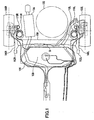
- A description will now be given, with reference to FIGS. 1 and 2, of a torsion beam type suspension. FIG. 1 is a plan view of a torsion beam type suspension provided in a vehicle. FIG. 2 is a side view of the torsion beam type suspension shown in FIG. 3.
- The torsion beam type suspension includes left and right trailing
arms arms arms 160A and 160R so as to rotatably support thewheels coil springs 112L and 112R are attached to the left and right trailingarms - A
torsion beam 150 is provided between the left and right trailingarms arms torsion beam 150 are welded to the left and right trailingarms - When the vehicle equipped with the torsion beam type suspension runs on a road surface having an unevenness, the left and right wheels vibrates up and down. If the unevenness on the road surface is in the same phase on the left and right sides, the left and right wheels vibrate in the same phase. If the unevenness on the road surface is in opposite phase on the left and right sides, the left and right wheels vibrate up and down in opposite phase. Additionally, even when the vehicle is running on a flat road surface, the vehicle body rolls due to a centrifugal force when the vehicle turns, which causes the left and right wheels to vibrate up and down in opposite phase.
- The above-mentioned up and down vibration of the wheels are transmitted to the left and right trailing
arms arms torsion beam 150 entirely swing about a line connecting thebushes arms shock absorbers - On the other hand, if they are in opposite phase stroke, the left and right trailing
arms torsion beam 150. Thus, a counter force to return the torsion is generated so as to prevent the vehicle from rolling. - In the design of the torsion beam type suspension, a position of a shear center of the torsion beam, which gives a considerable influence to an alignment change, is an important index. In the example of FIG. 1, if the cross-section of the
torsion beam 150 has a U-shape which opens rearward, a point B immediately in front of thetorsion beam 150 in the middle of thetorsion beam 150 is the shear center. In this case, the performance and characteristic of the suspension remarkably changes in accordance with the position of the shear center B. - In a case where the shear center B of the
torsion beam 150 is set to a point A, which is behind the point B, so as to achieve an optimum alignment change, it may be difficult to displace thetorsion beam 150 rearward depending on a positional relationship with a spare-tire house 102 or amuffler 104. On the other hand, in a case where the shear center B of thetorsion beam 150 is set to a point, which is ahead of the point B, it may be difficult to displace thetorsion beam 150 due to a relationship with afuel tank 108. Similarly, in a case where the shear center B of thetorsion beam 150 is set to a point, which is above or under the point B, anexhaust pipe 106 or the like may be an obstacle to the displacement of thetorsion beam 150. - Moreover, when the wheels bound and rebound, the left and right trailing
arms right bushes arms torsion beam 150 moves up and down. Accordingly, it is necessary to consider the arrangement to maintain a space between thetorsion beam 150 and theexhaust pipe 106 by bending theexhaust pipe 106 upward so that thetorsion beam 150 does not contact with theexhaust pipe 106 even when the torsion beam 105 moves up and down. - As mentioned above, in the torsion beam type suspension of rear wheels, there are various components around the
torsion beam 150, such as the spare-tire house 102, themuffler 104, theexhaust pipe 106, thefuel tank 108, etc, and there may be a physical limitation given by those components when determining arrangement and configuration of thetorsion beam 150. Thus, there may be a case where it is difficult to achieve an ideal alignment change. Additionally, there may occur a situation where arrangement and configuration of the surrounding components must be changed to achieve an optimum alignment change. - The applicant recognized that there are the above-mentioned problems in the torsion beam type suspension, and made the present invention. A description will be given below, with reference to the drawings, of a structure of an axle suspension apparatus according to an background art of the present invention.
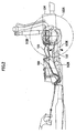
- FIG. 3 is a perspective view showing a structure of an axle suspension apparatus according to a background art of the present invention. In the axle suspension apparatus, a pair of left and right trailing
arms beam 10 extends in a direction of width of the vehicle and is bridged between the left and right trailingarms arms arms body support parts coupling parts wheel support parts beam 10 are rotatably connected toconnection parts arms - The
body support parts arms arms arms - The
coupling parts arms coupling parts beam 10, are not parallel to a direction of width of the vehicle body but at angles with respect to the direction of width of the vehicle. That is, the rotation axes X1L and X1R of the left and right ends of thebeam 10 are offset with respect to a straight line X0, which connects center points of thebody support parts arms body support parts beam 10 offset from the direction of width of the vehicle is determined according to suspension mechanism design aiming at an optimum geometric alignment change. - If the wheels attached to the
wheel support parts arms arms body support parts body support parts arms - On the other hand, when the left and right wheels are displaced up and down in opposite phase and a stroke difference is generated between the left and right wheels, the left and right trailing
arms beam 10 is referred to as "left and right rotation axes intersection". For example, when the right wheel bounds and the left wheel rebounds, theright trailing arm 20R swings upward with a straight line X2R, which connects the left and right rotation axes intersection A and the center of the rightbody support part 22R, as an axis of swing, while theleft trailing arm 20L swings downward with a straight line X2L, which connects the left and right rotation axes intersection A and the center of the leftbody support part 22L, as an axis of swing. The straight line X2R, which connects the left and right rotation axes intersection A and the center of the rightbody support part 22R, and the straight line X2L, which connects the left and right rotation axes intersection A and the center of the leftbody support part 22L, serve as axes of swing at the time of opposite phase stroke. - When the left and right rotation axes intersection A is located above the center points of the
body support parts arms - The position of the left and right rotation axes intersection A can be adjusted freely by changing orientation of the rotation axes X1L and X1R of the left and right ends of the
beam 10. Accordingly, there is no need to change the connecting positions between thebeam 10 and the trailingarms beam 10 when setting an alignment. - Moreover, even if the left and right trailing
arms beam 10 is not welded to the left and right trailingarms coupling parts beam 10 according to the present embodiment is not a member which deforms by torsion, and can be considered as a rigid member which is not twisted. - Since the
beam 10 is not twisted, a freedom in selection of materials is high. Moreover, since thebeam 10 is not welded to be connected to the left and right trailingarms beam 10 and the left and right trailingarms - Moreover, since the
beam 10 does not share torsion rigidity, a freedom in its shape is high and there is no problem if a bent portion exists in the middle of thebeam 10. Accordingly, thebeam 10 can be bent in an appropriate shape so as to avoid interference with various components of the vehicle arranged around thebeam 10, which increases a freedom of design. - A description will now be given, with reference to FIG. 4 and FIG. 5, of a structure of the
coupling parts beam 10 with the left and right trailingarms right coupling parts arms right trailing arm 20R. - FIG. 4 illustrates the structure of the
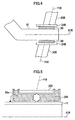
coupling part 24R which connects thebeam 10 to the trailingarm 20R. The rotation axis X1R of thebeam 10 and the center axis Y1R of the tight trailing arm 20 are not perpendicular to each other but thebeam 10 is obliquely connected to theright trailing arm 20R. Abush 30 is provided between thebeam 10 and thecoupling part 24R of the trailingarm 20R so that thebeam 10 is rotatably supported by thecoupling part 24R of theright trailing arm 20R. - FIG. 5 is a cross-sectional view showing an internal structure of the
coupling part 24R shown in FIG. 4. Two pieces ofbushes pipe 11 of theright trailing arm 20R and atube 25R of thecoupling part 24R so that thepipe 11 of the beam side and thetube 25R of the trailing arm side are elastically connected with each other. Since thepushes beam 10 can rotate smoothly about the rotation axis X1R in a state where thebeam 10 is retained by thecoupling part 24R of theright trailing arm 20R. Additionally, a vibration from a road surface can be absorbed by an elastic deformation ofbushes - A description will now be given, with reference to FIG. 6 and FIG. 7, of another structure of the
coupling parts beam 10 to the left and right trailingarms right coupling parts right coupling parts right trailing arm 20R. - FIG. 6 is an illustration showing an internal structure of the
coupling part 24R, which connects the beam 10to theright trailing arm 20R. Unlike the structure shown in FIG. 4, anangular bearing 40 is provided between thebeam 10 and thecoupling part 24R of theright trailing arm 20R so that thebeam 10 is rotatably connected to thecoupling part 24R of the trailingarm 20R. - FIG. 7 is a cross-sectional view showing an internal structure of the
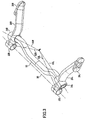
coupling part 24R shown in FIG. 6.Angular bearings tube 25R between thepipe 11 of thebeam 10 and thetube 25R of thecoupling part 24R. Theangular bearings washer 42 and abolt 44 together with thetube 25R so that the pipe 11on the beam side is rotatably connected to thetube 25R on the trailing arm side. Theangular bearings reference numbers angular bearings beam 10 can be rotated about the rotation axis X1R smoothly in a state where thebeam 10 is held by thecoupling part 24R of theright trailing arm 20R. - FIG. 8 is a perspective view of an axle suspension apparatus according to an embodiment of the present invention. In the axle suspension apparatus according to the present embodiment, the
beam 10 is bent so that amiddle part 12 of thebeam 10 is located on and extends along the in-phase stroke swing axis X0, which connect the center of the vehiclebody support parts arms 30L and 20R swing in the same phase with the in-phase stroke swing axis X0 as an axis of swing, themiddle part 12 of thebeam 10 does not move since the middle part is on the in-phase stroke swing axis X0. On the other hand, when the left and right wheels are displaced up and down in opposite phase, themiddle part 12 of thebeam 10 is on the in-phase stroke swing axis X0 and hardly moves. - As explained with reference to FIG. 2, in the conventional torsion beam type suspension, it is necessary to reserve a space for the
torsion beam 150 to swing up and down by bending theexhaust pipe 106 upward so as to avoid interference with theexhaust pipe 106 since thetorsion beam 150 swings up and down at the time of the same phase stroke. In the axle suspension apparatus according to the present embodiment, themiddle part 12 of thebeam 10 is made coincide with the in-phase stroke swing axis X0 so that themiddle part 12 of thebeam 10 does not move at the time of the same phase stroke and also at the time of opposite phase stroke. Thereby, there is no need to reserve the space for movement of thebeam 10, which further increases the freedom of design of a vehicle. - FIG. 9 is a perspective view of an axle suspension apparatus according to a further background art of the present invention. In the axle suspension apparatus, a
stabilizer 50 is provided so as to increase torsion rigidity at the time of opposite phase stroke. Since thebeam 10 is rotatably connected to thecoupling parts arms beam 10 itself is not twisted even at the time of opposite phase stroke. Thus, in order to give sufficient torsion rigidity, thestabilizer 50 is bridged between the left and right trailingarms stabilizer 50 are fixed to the left and right trailingarms bolts 52, respectively, so that the left and right trailingarms - By providing the
stabilizer 50, torsion rigidity is given to the pair of left and right trailingarms arms left trailing arm 20L swings upward with the opposite phase stroke swing axis X2L as an axis of swing and theright trailing arm 20R swings downward with the opposite phase stroke swing axis X2R as an axis of swing. A twist is generated in thestabilizer 50, which bridges between left and right trailingarms arms - FIG. 10 is a plan view showing an example in which the axle suspension apparatus according to one of the background arts is mounted on a vehicle. In the example shown in FIG. 10, the left and right rotation axes intersection A of the
beam 10 is located behind thebeam 10 in the rear of the vehicle so as to achieve an optimum alignment change. Although the left and right rotation axes intersection A is located in the spare-tire house 102, there is no need to change the connecting positions of thebeam 10 to the left and right trailingarms beam 10. - Due to the rotation axes X1L andX1R of the left and right ends of the
beam 10 being orientated toward the rear of the vehicle, thebeam 10 is bent toward the rear of the without changes, which may cause thebeam 10 to interfere with themuffler 104 or the spare-tire house 102. Thus, the middle part of thebeam 10 is bent toward the front of the vehicle so as to avoid interference with themuffler 104 and the spare-tire house 102. Since thebeam 10 does not share torsion rigidity, thebeam 10 can be of an arbitrary shape. Since there is no need to change the positions and shapes of the components surrounding thebeam 10 in the vehicle to achieve an optimum alignment change, there is no case where the freedom of design of the surrounding components is sacrificed. - Moreover, although the positional relationship of the left and right rotation axes intersection A relative to the center points of the vehicle
body support parts arms beam 10 up and down without changing the position of thebeam 10. Thus, an optimum alignment change can be achieved without changing arrangement and shape of the surrounding components such as theexhaust pipe 106 located above or under thebeam 10. - As explained above, according to the axle suspension apparatuses of the above-mentioned embodiments, an optimum alignment change can be achieved by merely changing the orientation of the rotation axes X1L and X1R of the left and right ends of the
beam 10 without changing the positions of thecoupling parts arms arms beam 10. - Therefore, when mounting the axle suspension apparatus, the arrangement and shape of the
beam 10 can be determined in accordance with the positional relationship with the surrounding components of the vehicle and an optimum alignment change can be determined by adjusting the orientation of the rotation axes of the left and right ends of thebeam 10 independently from the arrangement and shape of thebeam 10, which permits designing of the axle suspension apparatus without restrictions. Thus, a freedom in the suspension mechanism design is remarkably improved. - Since the intersection of the rotation axes of the left and right ends of the
beam 10, which is important for achieving an optimum alignment change, can be set independently from the position and shape of thebeam 10, a toe change or a camber change when a vehicle rolls can be designed optimally without restrictions of spaces in front of, behind, above or under thebeam 10. Additionally, since thebeam 10 is rotatably connected to the left and right trailingarms beam 10 is not twisted at the time of opposite phase stroke and there is no influence given to a toe change or a camber change even if there is a bent portion in the middle of thebeam 10. Further, since thebeam 10 is not given a direct shock due to twisting, reliability of the axle suspension apparatus is improved. - Although the
beam 10 is formed in a pipe shape so as to be easily bent, other forms may be used for thebeam 10. Additionally, the left and right ends of thebeam 10 are rotatably connected to thecoupling parts arms coupling parts
Claims (5)
- An axle suspension apparatus comprising:a pair of left and right arms (20L, 20R) each having a vehicle body support part (22L, 22R) supported on a vehicle body and a wheel support part (26L, 26R) supporting a wheel (100L, 100R);a beam (10) provided between said left and right arms (20L, 20R), both ends of the beam (10) being rotatably connected to the respective left and right arms (20L, 20R) between the vehicle body support part (22L, 22R) and the wheel support part (26L, 26R) of the each arm (20L, 20R);rotation axes (X1L, X1R) of the both ends of said beam (10) being at angles with respect to a line connecting the both ends of said beam (10),characterized in that
a middle part (12) of said beam (10) extends along a line (X0) connecting said vehicle body support parts (22L, 22R). - The axle suspension apparatus as claimed in claim 1, further comprising a stabilizer (50) bridged between said left and right arms (20L, 20R).
- The axle suspension apparatus as claimed in claim 1 or 2, further comprising a bush (30) provided between each end of said beam (10) and a respective one of said left and right arms (20L, 20R), the bush (30) including an elastic member that roatatably connects each end of said beam (10) to the respective one of said left and right arms (20L, 20R).
- The axle suspension apparatus as claimed in claim 1 or 2, further comprising a bearing (40) provided between each end of said beam (10) and a respective one of said left and right arms (20L, 20R), the bearing (40) rotatably connecting each end of said beam (10) to the respective one of said left and right arms (20L, 20R).
- The axle suspension apparatus as claimed in one of claims 1 to 4, wherein said beam (10) is bent so as to avoid said beam (10) from interfering with components surrounding said beam (10).
Applications Claiming Priority (1)
| Application Number | Priority Date | Filing Date | Title |
|---|---|---|---|
| JP2004369867A JP4389774B2 (en) | 2004-12-21 | 2004-12-21 | Axle suspension |
Publications (2)
| Publication Number | Publication Date |
|---|---|
| EP1674307A1 EP1674307A1 (en) | 2006-06-28 |
| EP1674307B1 true EP1674307B1 (en) | 2007-10-17 |
Family
ID=35519743
Family Applications (1)
| Application Number | Title | Priority Date | Filing Date |
|---|---|---|---|
| EP05026759A Expired - Fee Related EP1674307B1 (en) | 2004-12-21 | 2005-12-07 | Axle suspension apparatus |
Country Status (3)
| Country | Link |
|---|---|
| EP (1) | EP1674307B1 (en) |
| JP (1) | JP4389774B2 (en) |
| DE (1) | DE602005002921T2 (en) |
Families Citing this family (10)
| Publication number | Priority date | Publication date | Assignee | Title |
|---|---|---|---|---|
| FR2898543A1 (en) * | 2006-03-20 | 2007-09-21 | Renault Sas | Rear flexible axle for motor vehicle, has crosspiece with central part separated vertically towards top with respect to anchoring points of crosspiece, where crosspiece connects longitudinal arms at level of points |
| DE102008010614B4 (en) * | 2008-02-22 | 2016-06-30 | Zf Friedrichshafen Ag | Axle suspension for a vehicle |
| FR2944736B1 (en) * | 2009-04-28 | 2012-12-21 | Renault Sas | MOTOR VEHICLE TRAIN. |
| JP5365480B2 (en) * | 2009-11-19 | 2013-12-11 | トヨタ車体株式会社 | Vehicle torsion beam suspension |
| JP5440930B2 (en) * | 2009-11-26 | 2014-03-12 | スズキ株式会社 | Torsion beam suspension |
| DE102010036949A1 (en) * | 2010-08-11 | 2012-02-16 | Muhr Und Bender Kg | Cross member for a torsion beam axle |
| DE102011104865A1 (en) * | 2011-06-22 | 2012-12-27 | GM Global Technology Operations LLC (n. d. Gesetzen des Staates Delaware) | Arrangement for the rear of a motor vehicle with a filling line for fuel and a torsion beam axle |
| CN107531120B (en) | 2015-05-08 | 2020-12-25 | 麦格纳国际公司 | Adjustable vehicle suspension assembly |
| JP6479900B2 (en) * | 2017-07-04 | 2019-03-06 | 本田技研工業株式会社 | Torsion beam suspension structure and vehicle |
| CN107764151A (en) * | 2017-11-08 | 2018-03-06 | 浙江德昱汽车零部件有限公司 | Torsion beam detection utensil afterwards |
Family Cites Families (11)
| Publication number | Priority date | Publication date | Assignee | Title |
|---|---|---|---|---|
| GB814306A (en) * | 1955-12-29 | 1959-06-03 | Engineering Res & Applic Ltd | Improvements in or relating to suspension means for the rear-wheels of a motor car |
| ES357884A1 (en) * | 1968-08-29 | 1970-03-01 | Sevilla Enciso | Improvements in the means of suspension of vehicles. (Machine-translation by Google Translate, not legally binding) |
| DE3016248C2 (en) * | 1980-04-26 | 1986-10-23 | Adam Opel AG, 6090 Rüsselsheim | Rear axles for vehicles, in particular for motor vehicles |
| IT1160120B (en) * | 1983-04-18 | 1987-03-04 | Fiat Auto Spa | IMPROVEMENTS FOR MOTOR VEHICLE SUSPENSION SYSTEMS |
| FR2547540A1 (en) * | 1983-06-17 | 1984-12-21 | Citroen Sa | Vehicle carrier axle |
| FR2662118A1 (en) * | 1990-05-17 | 1991-11-22 | Peugeot | REAR TRAIN OF A MOTOR VEHICLE. |
| US5215329A (en) * | 1990-11-22 | 1993-06-01 | Toyota Jidosha Kabushiki Kaisha | Twist beam type rear suspension reinforced against side force with longitudinal compliance |
| DE4445995C1 (en) * | 1994-12-22 | 1996-04-18 | Fichtel & Sachs Ag | Wheel suspension for vehicle axle |
| JP3546564B2 (en) * | 1995-03-24 | 2004-07-28 | トヨタ自動車株式会社 | Twist beam suspension |
| JP3503455B2 (en) * | 1998-01-13 | 2004-03-08 | トヨタ自動車株式会社 | Vehicle |
| FR2805776B1 (en) | 2000-03-02 | 2003-06-27 | Michelin & Cie | FLEXIBLE AXLE FOR A MOTOR VEHICLE WITH IMPROVED ANTI-ROLL DEVICE |
-
2004
- 2004-12-21 JP JP2004369867A patent/JP4389774B2/en not_active Expired - Fee Related
-
2005
- 2005-12-07 EP EP05026759A patent/EP1674307B1/en not_active Expired - Fee Related
- 2005-12-07 DE DE200560002921 patent/DE602005002921T2/en active Active
Non-Patent Citations (1)
| Title |
|---|
| None * |
Also Published As
| Publication number | Publication date |
|---|---|
| DE602005002921D1 (en) | 2007-11-29 |
| JP4389774B2 (en) | 2009-12-24 |
| DE602005002921T2 (en) | 2008-07-31 |
| EP1674307A1 (en) | 2006-06-28 |
| JP2006175946A (en) | 2006-07-06 |
Similar Documents
| Publication | Publication Date | Title |
|---|---|---|
| EP1674307B1 (en) | Axle suspension apparatus | |
| EP1757468B1 (en) | Suspension device | |
| JP3550908B2 (en) | Front suspension device | |
| EP2355987B1 (en) | Vehicle independent suspension | |
| JP5136453B2 (en) | Stabilizer link mounting structure | |
| JP2003335117A (en) | Rear wheel suspension device for car | |
| US7607671B2 (en) | Light weight suspension system | |
| US20060091721A1 (en) | Torsion beam suspension system for automobiles and method of manufacturing the same | |
| US6062580A (en) | Front suspension of motor vehicle | |
| JP2006347338A (en) | Rear suspension device for automobile | |
| JP2006347337A (en) | Rear suspension device for automobile | |
| JP3468014B2 (en) | Trailing arm support structure for vehicle suspension | |
| KR101121898B1 (en) | Tortion Beam Axle for Vehicle | |
| JPH09263116A (en) | Stabilizer mounting structure | |
| KR100326663B1 (en) | Multi camber mode suspension | |
| JP4998115B2 (en) | Suspension device | |
| JP2005506922A (en) | Method and apparatus for suspending a vehicle wheel assembly | |
| JPH07232524A (en) | Suspension for driving wheel | |
| JP4534153B2 (en) | Rear suspension device for automobile | |
| JP2007106193A (en) | Suspension device for steering wheel | |
| JP3645446B2 (en) | Trailing arm suspension | |
| JP4266327B2 (en) | Automotive suspension | |
| JP3969367B2 (en) | Multi-link rear wheel suspension system for automobiles | |
| JP2000043529A (en) | Front suspension device | |
| JPS6053409A (en) | Rear suspension of car |
Legal Events
| Date | Code | Title | Description |
|---|---|---|---|
| PUAI | Public reference made under article 153(3) epc to a published international application that has entered the european phase |
Free format text: ORIGINAL CODE: 0009012 |
|
| 17P | Request for examination filed |
Effective date: 20051222 |
|
| AK | Designated contracting states |
Kind code of ref document: A1 Designated state(s): AT BE BG CH CY CZ DE DK EE ES FI FR GB GR HU IE IS IT LI LT LU LV MC NL PL PT RO SE SI SK TR |
|
| AX | Request for extension of the european patent |
Extension state: AL BA HR MK YU |
|
| 17Q | First examination report despatched |
Effective date: 20060904 |
|
| AKX | Designation fees paid |
Designated state(s): DE FR IT |
|
| GRAP | Despatch of communication of intention to grant a patent |
Free format text: ORIGINAL CODE: EPIDOSNIGR1 |
|
| GRAS | Grant fee paid |
Free format text: ORIGINAL CODE: EPIDOSNIGR3 |
|
| GRAA | (expected) grant |
Free format text: ORIGINAL CODE: 0009210 |
|
| AK | Designated contracting states |
Kind code of ref document: B1 Designated state(s): DE FR IT |
|
| REF | Corresponds to: |
Ref document number: 602005002921 Country of ref document: DE Date of ref document: 20071129 Kind code of ref document: P |
|
| ET | Fr: translation filed | ||
| PLBE | No opposition filed within time limit |
Free format text: ORIGINAL CODE: 0009261 |
|
| STAA | Information on the status of an ep patent application or granted ep patent |
Free format text: STATUS: NO OPPOSITION FILED WITHIN TIME LIMIT |
|
| 26N | No opposition filed |
Effective date: 20080718 |
|
| REG | Reference to a national code |
Ref country code: DE Ref legal event code: R084 Ref document number: 602005002921 Country of ref document: DE Effective date: 20120924 |
|
| REG | Reference to a national code |
Ref country code: FR Ref legal event code: PLFP Year of fee payment: 11 |
|
| REG | Reference to a national code |
Ref country code: FR Ref legal event code: PLFP Year of fee payment: 12 |
|
| REG | Reference to a national code |
Ref country code: FR Ref legal event code: PLFP Year of fee payment: 13 |
|
| PGFP | Annual fee paid to national office [announced via postgrant information from national office to epo] |
Ref country code: DE Payment date: 20181127 Year of fee payment: 14 |
|
| PGFP | Annual fee paid to national office [announced via postgrant information from national office to epo] |
Ref country code: FR Payment date: 20181122 Year of fee payment: 14 |
|
| PGFP | Annual fee paid to national office [announced via postgrant information from national office to epo] |
Ref country code: IT Payment date: 20181220 Year of fee payment: 14 |
|
| REG | Reference to a national code |
Ref country code: DE Ref legal event code: R119 Ref document number: 602005002921 Country of ref document: DE |
|
| PG25 | Lapsed in a contracting state [announced via postgrant information from national office to epo] |
Ref country code: DE Free format text: LAPSE BECAUSE OF NON-PAYMENT OF DUE FEES Effective date: 20200701 Ref country code: FR Free format text: LAPSE BECAUSE OF NON-PAYMENT OF DUE FEES Effective date: 20191231 Ref country code: IT Free format text: LAPSE BECAUSE OF NON-PAYMENT OF DUE FEES Effective date: 20191207 |