EP1673575B1 - Gas turbine engine with an aerodynamic trip - Google Patents
Gas turbine engine with an aerodynamic trip Download PDFInfo
- Publication number
- EP1673575B1 EP1673575B1 EP04737956A EP04737956A EP1673575B1 EP 1673575 B1 EP1673575 B1 EP 1673575B1 EP 04737956 A EP04737956 A EP 04737956A EP 04737956 A EP04737956 A EP 04737956A EP 1673575 B1 EP1673575 B1 EP 1673575B1
- Authority
- EP
- European Patent Office
- Prior art keywords
- combustor
- chamber
- compressor
- gas turbine
- turbine engine
- Prior art date
- Legal status (The legal status is an assumption and is not a legal conclusion. Google has not performed a legal analysis and makes no representation as to the accuracy of the status listed.)
- Expired - Lifetime
Links
Images


Classifications
-
- F—MECHANICAL ENGINEERING; LIGHTING; HEATING; WEAPONS; BLASTING
- F23—COMBUSTION APPARATUS; COMBUSTION PROCESSES
- F23R—GENERATING COMBUSTION PRODUCTS OF HIGH PRESSURE OR HIGH VELOCITY, e.g. GAS-TURBINE COMBUSTION CHAMBERS
- F23R3/00—Continuous combustion chambers using liquid or gaseous fuel
- F23R3/002—Wall structures
-
- F—MECHANICAL ENGINEERING; LIGHTING; HEATING; WEAPONS; BLASTING
- F23—COMBUSTION APPARATUS; COMBUSTION PROCESSES
- F23R—GENERATING COMBUSTION PRODUCTS OF HIGH PRESSURE OR HIGH VELOCITY, e.g. GAS-TURBINE COMBUSTION CHAMBERS
- F23R3/00—Continuous combustion chambers using liquid or gaseous fuel
- F23R3/02—Continuous combustion chambers using liquid or gaseous fuel characterised by the air-flow or gas-flow configuration
- F23R3/04—Air inlet arrangements
-
- F—MECHANICAL ENGINEERING; LIGHTING; HEATING; WEAPONS; BLASTING
- F23—COMBUSTION APPARATUS; COMBUSTION PROCESSES
- F23D—BURNERS
- F23D2210/00—Noise abatement
-
- F—MECHANICAL ENGINEERING; LIGHTING; HEATING; WEAPONS; BLASTING
- F23—COMBUSTION APPARATUS; COMBUSTION PROCESSES
- F23R—GENERATING COMBUSTION PRODUCTS OF HIGH PRESSURE OR HIGH VELOCITY, e.g. GAS-TURBINE COMBUSTION CHAMBERS
- F23R2900/00—Special features of, or arrangements for continuous combustion chambers; Combustion processes therefor
- F23R2900/00014—Reducing thermo-acoustic vibrations by passive means, e.g. by Helmholtz resonators
-
- Y—GENERAL TAGGING OF NEW TECHNOLOGICAL DEVELOPMENTS; GENERAL TAGGING OF CROSS-SECTIONAL TECHNOLOGIES SPANNING OVER SEVERAL SECTIONS OF THE IPC; TECHNICAL SUBJECTS COVERED BY FORMER USPC CROSS-REFERENCE ART COLLECTIONS [XRACs] AND DIGESTS
- Y02—TECHNOLOGIES OR APPLICATIONS FOR MITIGATION OR ADAPTATION AGAINST CLIMATE CHANGE
- Y02T—CLIMATE CHANGE MITIGATION TECHNOLOGIES RELATED TO TRANSPORTATION
- Y02T50/00—Aeronautics or air transport
- Y02T50/60—Efficient propulsion technologies, e.g. for aircraft
Definitions
- the present invention relates to a method and apparatus for improving combustion, and particularly gas turbine engine combustion.
- One object of the present invention is to provide improved combustion, and particularly that which would be beneficial to gas turbine engines.
- the invention provides a gas turbine engine comprising: a combustor portion including at least one combustor, the combustor having a plurality of holes therein for admitting combustion air into the combustor; a casing defining at least one chamber therein, the chamber containing the combustor and a volume of air around at least a portion of the combustor; a compressor portion communicating with the chamber via a compressor diffuser outlet for delivering compressed air to the chamber for subsequent admission into the combustor; and characterized in that at least one trip extends into the chamber and is positioned downstream of the compressor diffuser outlet so as to extend partially into an air flow exiting the compressor diffuser outlet into the chamber, causing a step change in direction and pressure of at least a portion of the air flow to effect a redistribution of air around the combustor to thereby achieve at least one of reduced combustion noise and more uniform temperature distribution in the combustor.
- the invention provides a method for improving at least one of a temperature distribution and a combustion noise level in a combustor of a combustion system, the combustion system having a chamber housing the combustor, a compressor portion for providing a flow of compressed air to the chamber via a compressor diffuser outlet, the combustor having holes therein for admitting the compressed air into the combustor for combustion therein when mixed with fuel and ignited, the method characterised by a step of providing at least one trip extending into the chamber and positioned downstream of the compressor diffuser outlet so as to extend partially into an air flow exiting the compressor diffuser outlet into the chamber, causing a step change in direction and pressure of at least a portion of the air flow to effect a redistribution of air around the combustor to thereby achieve at least one of reduced combustion noise and more uniform temperature distribution in the combustor.
- the invention provides a method of providing a gas turbine engine, the method comprising the steps of: determining a configuration for a combustor, a casing chamber surrounding the combustor, and a compressor portion communicating with the chamber via a compressor diffuser outlet, the configuration including an air flow path from the compressor diffuser outlet through the casing chamber and into the combustor; determining an initial operating direction and air pressure distribution occurring in the compressed air flow in the chamber around the combustor and characterized by steps of: determining a desired step change in direction and air pressure in at least a portion of the compressed air flow in the chamber to effect a redistribution of air around the combustor, the redistribution being determined to provide at least one of reduced combustion noise and improved temperature distribution in the combustor; and introducing at least one trip extending into the casing chamber and positioned downstream of the compressor diffuser outlet so as to extend into the flow path to effect the determined air pressure redistribution.
- Fig. 1 is a schematic cross-sectional view of a gas turbine engine incorporating one embodiment of the present invention
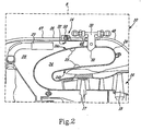
- Fig. 2 is a cross-sectional view of Detail 8 of Fig. 1 ;
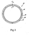
- Fig. 3 is a front elevational view of an aerodynamic trip ring of Fig. 2 ;
- Fig. 4 is a cross-sectional view taken among Line 4-4 of Fig. 3 ;
- Fig. 4a is a cross-sectional view similar to Fig. 4 or an alternate embodiment
- FIGs. 5a and 5b depict another alternate embodiment of the invention.
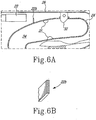
- FIGs. 6a and 6b depict a further alternate embodiment of the invention.
- Figs. 7a and 7b depict another embodiment of the invention.
- a gas turbine engine 10 which is illustrated as an APU but can be any type of gas turbine engine, includes an embodiment of the present invention.
- Engine 10 generally comprises a compressor region 12, a combustor region 14 and a turbine region 16.
- the compressor region 12 generally includes a high pressure compressor 18 for providing a high pressure compressor air flow for combustion and for cooling of the engine.
- a compressor diffuser 20 is positioned downstream of the high pressure compressor 18 and extends into the combustor region 14 for reducing the velocity which increases the pressure of compressor air flow and for delivering the compressor air flow to the combustor region 14.
- a tripping device in this embodiment preferably an aerodynamic trip ring 22, is provided in the combustor region 14 for intervening in the compressor air flow before the compressor air flow enters a combustor 24 for combustion, as will be described in detail with reference to Fig. 2 , below.
- the turbine region 16 includes high pressure turbine 17 and powering turbine 19. The combustion gases generated from the combustor region 14 enter the turbine region 16 for powering the respective turbines 17 and 19.
- Fig. 2 taken from Detail 8 of Fig. 1 , depicts the combustor region 14 in greater detail.
- the combustor region 14 is defined by a substantially cylindrical casing 26, preferably surrounding at least a downstream section of the compressor diffuser 20 and the combustor 24, (which is shown as an annular combustor, though any suitable combustor shape may be used), thereby forming a chamber 28 surrounding a volume of air and the combustor 24.
- Combustor 24 has a radially outer side 24a and a radially inner side 24b.
- the casing serves to help direct the compressor air flow from the compressor diffuser 20 to the combustor, and thereby defines a flow path portion 46 downstream of the compressor diffuser 20 to the combustor 24.
- the compressor 24 is supported within the chamber 28 by a suitable support structure 30 which secures the annular combustor 24 to the casing 26.
- a plurality of fuel nozzles 32 extend into the combustor 24.
- the combustor 24 further includes a plurality of apertures 25 therethrough so that the chamber 28 is in fluid communication with a combustor chamber 34 defined within the combustor 24.
- the fuel nozzles 32 inject fuel into the combustion chamber 34 to be mixed with compressor air flow having entered from the chamber 28 into the combustor 24.
- the fuel and air mixture is then ignited to generate expanding combustion gases, which then enter the turbine section 16 for driving the high pressure turbine 17 and the power turbine 19.
- the compressor air flow exiting the compressor region generally carries fluctuation energy which is generated substantially during the air compressing course.
- the fluctuation energy carried in the compressor air flow includes both acoustic and hydraulic fluctuation components which present a broad band of high and low frequency signals. These high and low frequency signals when being delivered into the combustor 24 by the compressor air flow, will be amplified during the combustion reaction in the combustion chamber 34, thereby creating a high level of the combustion noise.
- the fluctuation energy carried and delivered into the combustor 24 by the compressor air flow adversely affects an even and uniform pressure distribution, which causes the less than optimum mixing of fuel with the compressor air flow within the combustor, thereby resulting in a poor dynamic temperature distribution within the combustion chamber 34, which in turn exacerbates amplification of the combustion noise level.
- the inventor has found that improvement can be achieved if the acoustic and hydraulic fluctuation components of the compressor air flow are decoupled before entry into the combustor.
- the invention presents an aerodynamic trip to effect a decoupling of the acoustic and hydraulic fluctuation components of the compressor air flow, as will now be described in more detail.
- the aerodynamic trip ring 22 is made of, for example, a suitable metal material or any other material suitable for the application and subject operating conditions, and includes a mounting portion including an axial section 36 and an outer radial section 38, and an inner radial trip section 40.
- the outer radial section 38 extends radially outwardly from the axial section 36 at one side thereof, and the inner radial section 40 extends radially inwardly from the axial section 36 at the other side thereof.
- a plurality of mounting openings 42 are provided in the outer radial section 38 in a circumferentially spaced apart relationship.
- the inner radial section 40 preferably includes an inner periphery 44 beveled at the outer side thereof.
- the casing 26 of a gas turbine engine is configured with an upstream section 46 and a downstream section 48 which are bolted together by a flange connection 50.
- the aerodynamic trip ring 22 is preferably secured to the inner side of the casing 26 by positioning the outer radial section 38 between the upstream and the downstream sections 47, 48 of the casing 26, and by receiving the flange connection bolts (not indicated) extending through the mounting openings 42.
- the axial section 36 of the aerodynamic trip ring 22 preferably has a radial dimension appropriate for abutting the inner side of the casing 26 in order to prevent the aerodynamic trip ring 22 from possible vibration caused by the effects of the fluctuation energy carried by the compressor air flow.
- the inner radial section 40 of the aerodynamic trip ring 22 extends into the flow path 46 of the compressor air flow within the chamber 28 downstream of the compressor diffuser 20.
- the beveled inner periphery 44 faces the compressor diffuser 20 when the aerodynamic trip ring 22 is mounted within the chamber 28.
- the aerodynamic trip ring 22 surrounding the annular combustor 24 imparts a perpendicular directional component to the compressor flow exiting the compressor and passing by the trip ring 22.
- the interaction of the air flow and the trip ring 22 creates a step change in the direction and pressure of the compressor air flow prior to entry of the air flow into the combustor 24, which beneficially improves both temperature distribution in the combustion and combustion noise levels in the combustor.
- the trip creates a step change in a direction of at least a portion of the compressor air flow which is believed to thereby diffuse the hydraulic fluctuation energy in the compressor air flow. Diffusion of this energy promotes redistribution of compressor air around the combustor 24 promotes better air distribution uniformity inside the combustion chamber 34, thereby resulting in better a mixing of the air and the fuel. Thus, the overall temperature distribution factor (OTDF) of the gas turbine engine combustion can be improved.
- the trip also causes a step change increase in the pressure drop in the air flow which, together with the direction change, results in an energy dissipation which is useful, when controlled according to the present teachings, in attenuating combustion noise.
- the local pressure drop around the combustor may therefore be beneficially redistributed, and the duration the compressor air flow resides within the chamber outside the combustor may be beneficially altered to permit the fluctuation components of the compressor air flow to be decoupled so that a subtractive cancelling effect on combustion noise is achieved in the combustor.
- the present invention therefore achieves a beneficial decoupling of compressor acoustic and hydrodynamic fluctuations prior to entry into the combustor.
- the step change in direction is achieved by a redirecting function performed by the trip.
- the step change pressure drop is achieved by one or more of a flow restricting function, a turbulence intensity increasing function and flow separation function of the trip. All elements contribute to an energy dissipation in the flow, and a corresponding frequency shift in the flow's acoustic and hydraulic components. It will be understood that a step change is not a continuous change over a distance travelled by the air flow, but rather a discontinuity in direction and or pressure drop.
- the configuration, size and location of the trip can be determined depending on the desired direction change and desired pressure drop to achieve the desired percentage of air redistribution around the combustor.
- the redistribution preferably occurs upstream of air entry into the combustor and downstream of the inlet into the chamber.
- the trip is preferably placed at a reasonable distance downstream so as not to cause choking, etc.
- the trip is preferably located close to the compressor outlet relative to the size of the chamber 28.
- the trip is placed relative to the compressor outlet to restructure the flow exiting the compressor before that flow enters the combustor.
- trip 22 may be designed to cause 10% more air to be redistributed towards the inner wall of the annular combustor (i.e. the lower wall, as depicted in Figure 2 ), which may thereby achieve a better pressure distribution about the combustor, achieve a desired frequency shift in the flow, etc.
- Full or partial redistribution of air flow velocity and pressure and diffusion of fluctuation energy in the air flow are thus both achieved by introducing a step change in velocity and pressure to the air flow.
- the hydrodynamic and acoustic structure imposed by the compressor on the air flow can be restructured according to the designer's preference prior to delivery to the combustor for combustion.
- the invention therefore permits combustor noise and combustion performance to be improved for a given combustor and fuel nozzle configuration without making changes to the combustor and/or fuel nozzle configuration. This permits the designed to optimize those components according to another set considerations.
- the pressure drop introduced by the trip will be not more than the pressure drop which is calculated to occur across the combustor in the same system operated without the trip present.
- the pressure drop selected by the designed will preferably range between 0 and this preferred maximum value.
- the use of the aerodynamic trip approach to affect the compressor air flow within the chamber 28 is a simple, convenient and practical approach executable entirely outside the combustor 24.
- the "tripped" compressor air flow permits a better temperature distribution and a relatively lower noise energy to be delivered to the combustion chamber 34, and thereby permits the overall acoustic nose level of the gas turbine engine combustion to be intentionally and controllably reduced relative to prior art "untripped" flows.
- an aerodynamic trip ring 22 may include a mounting portion with only the axial section 36 for mounting the inner radial trip section 40 to the engine.
- the mounting holes 42 or other mounting means may be defined in the axial section 36 of the mounting portion so that the aerodynamic trip ring 22 may be mechanically mounted directly to the inner side of the casing 22 at any selected axial position between compressor diffuser 20 and the support structure 30.
- the radial size of the axial section 36 should be properly fitted into an inner diameter of the casing 26.
- Any other suitable manner of mounting or mounting configuration may be likewise be used, such chemical bonding, welding, brazing, interlocking or other mechanical attachment or the feature may be integrally provided on an existing component.
- the trip means is positioned fluidly intermediate the compressor and the combustor.
- the trip means may be mounted to the casing 26, the combustor 24, the support structure 30, the compressor diffuser 20, or other suitable location.
- the trip need not be continuous or uniform around the combustor.
- a non-continuous non-ring-like trip means 22 particularly a plurality of baffle plates 22a, which may be provided with or without openings (without is shown), and which may be placed in the flow path 46 of the compressor air flow, mounted to the compressor diffuser 20.
- trip means 22 may be a plurality of deflector members 22b mounted to the combustor.
- trip means 22 may comprise multiple elements 22c extending into the flow path downstream of one another, etc.
- Any combustor type including can, cannular and annular type combustors, may be used.
- the volume or air around the combustor need not completely encircle or surround the combustor.
- the trip means is preferably arranged transversely relative to the original air flow outside the combustor, but need not be necessarily so.
- the trip means need not extend perpendicularly to the flow or radially relative to the engine centreline, those these are preferred by the inventor.
- the present approach may also be used advantageously to decouple imposed instabilities such as that which may arise from any feedback loop between imposed pressure oscillations by the compressor and fluctuation of combustor equivalence ratio or heat dissipation rate.
Landscapes
- Engineering & Computer Science (AREA)
- Chemical & Material Sciences (AREA)
- Combustion & Propulsion (AREA)
- Mechanical Engineering (AREA)
- General Engineering & Computer Science (AREA)
- Structures Of Non-Positive Displacement Pumps (AREA)
Applications Claiming Priority (2)
| Application Number | Priority Date | Filing Date | Title |
|---|---|---|---|
| US10/683,118 US7302802B2 (en) | 2003-10-14 | 2003-10-14 | Aerodynamic trip for a combustion system |
| PCT/CA2004/001021 WO2005036057A1 (en) | 2003-10-14 | 2004-07-19 | Aerodynamic trip for a combustion system |
Publications (2)
| Publication Number | Publication Date |
|---|---|
| EP1673575A1 EP1673575A1 (en) | 2006-06-28 |
| EP1673575B1 true EP1673575B1 (en) | 2012-05-02 |
Family
ID=34435392
Family Applications (1)
| Application Number | Title | Priority Date | Filing Date |
|---|---|---|---|
| EP04737956A Expired - Lifetime EP1673575B1 (en) | 2003-10-14 | 2004-07-19 | Gas turbine engine with an aerodynamic trip |
Country Status (5)
| Country | Link |
|---|---|
| US (1) | US7302802B2 (enExample) |
| EP (1) | EP1673575B1 (enExample) |
| JP (1) | JP2007508517A (enExample) |
| CA (1) | CA2542307C (enExample) |
| WO (1) | WO2005036057A1 (enExample) |
Families Citing this family (13)
| Publication number | Priority date | Publication date | Assignee | Title |
|---|---|---|---|---|
| US7461483B2 (en) * | 2006-09-11 | 2008-12-09 | Dana Innovations | Devices and methods for flangeless installations |
| FR2911669B1 (fr) * | 2007-01-23 | 2011-09-16 | Snecma | Carenage pour chambre de combustion, chambre de combustion en etant equipee et turboreacteur les comportant. |
| US9404441B2 (en) | 2008-08-18 | 2016-08-02 | Aerojet Rocketdyne Of De, Inc. | Low velocity injector manifold for hypergolic rocket engine |
| US9297532B2 (en) * | 2011-12-21 | 2016-03-29 | Siemens Aktiengesellschaft | Can annular combustion arrangement with flow tripping device |
| US9400110B2 (en) * | 2012-10-19 | 2016-07-26 | Honeywell International Inc. | Reverse-flow annular combustor for reduced emissions |
| US9239166B2 (en) * | 2012-10-29 | 2016-01-19 | Solar Turbines Incorporated | Gas turbine diffuser with flow separator |
| US20140165582A1 (en) * | 2012-12-17 | 2014-06-19 | United Technologies Corporation | Cross-flow turbine engine |
| US10724739B2 (en) | 2017-03-24 | 2020-07-28 | General Electric Company | Combustor acoustic damping structure |
| US10415480B2 (en) | 2017-04-13 | 2019-09-17 | General Electric Company | Gas turbine engine fuel manifold damper and method of dynamics attenuation |
| US11149948B2 (en) | 2017-08-21 | 2021-10-19 | General Electric Company | Fuel nozzle with angled main injection ports and radial main injection ports |
| US11156162B2 (en) | 2018-05-23 | 2021-10-26 | General Electric Company | Fluid manifold damper for gas turbine engine |
| US11506125B2 (en) | 2018-08-01 | 2022-11-22 | General Electric Company | Fluid manifold assembly for gas turbine engine |
| US11255266B2 (en) | 2019-05-14 | 2022-02-22 | Raytheon Technologies Corporation | Recuperated cycle engine |
Family Cites Families (26)
| Publication number | Priority date | Publication date | Assignee | Title |
|---|---|---|---|---|
| US2657531A (en) * | 1948-01-22 | 1953-11-03 | Gen Electric | Wall cooling arrangement for combustion devices |
| US3333414A (en) * | 1965-10-13 | 1967-08-01 | United Aircraft Canada | Aerodynamic-flow reverser and smoother |
| US3974647A (en) * | 1974-08-26 | 1976-08-17 | United Technologies Corporation | Combustion instability reduction device having swirling flow |
| US4380895A (en) * | 1976-09-09 | 1983-04-26 | Rolls-Royce Limited | Combustion chamber for a gas turbine engine having a variable rate diffuser upstream of air inlet means |
| US4796429A (en) | 1976-11-15 | 1989-01-10 | General Motors Corporation | Combustor diffuser |
| US4122674A (en) * | 1976-12-27 | 1978-10-31 | The Boeing Company | Apparatus for suppressing combustion noise within gas turbine engines |
| US4531356A (en) * | 1981-06-15 | 1985-07-30 | The Garrett Corporation | Intake vortex whistle silencing apparatus and methods |
| US4606721A (en) * | 1984-11-07 | 1986-08-19 | Tifa Limited | Combustion chamber noise suppressor |
| FR2685386B1 (fr) * | 1991-12-20 | 1994-03-25 | Propulsion Ste Europeenne | Systeme d'amortissement des instabilites de combustion haute frequence dans une chambre de combustion. |
| US5644918A (en) * | 1994-11-14 | 1997-07-08 | General Electric Company | Dynamics free low emissions gas turbine combustor |
| JPH09170716A (ja) * | 1995-12-19 | 1997-06-30 | Hitachi Ltd | 燃料予混合装置及びガスタービン燃焼装置 |
| DE59709155D1 (de) * | 1997-07-15 | 2003-02-20 | Alstom Switzerland Ltd | Vorrichtung zur Dämpfung von Brennkammerschwingungen |
| GB2328011A (en) * | 1997-08-05 | 1999-02-10 | Europ Gas Turbines Ltd | Combustor for gas or liquid fuelled turbine |
| US6464489B1 (en) * | 1997-11-24 | 2002-10-15 | Alstom | Method and apparatus for controlling thermoacoustic vibrations in a combustion system |
| ATE371877T1 (de) * | 1998-03-03 | 2007-09-15 | Ccs Technology Inc | Einlegungsvorrichtung zum einlegen eines langgestreckten schutzprofils oberhalb eines in einer verlegenut verlegten kabels |
| EP1073864B1 (de) * | 1998-04-23 | 2002-07-03 | Siemens Aktiengesellschaft | Brennkammeranordnung |
| DE59810347D1 (de) * | 1998-09-10 | 2004-01-15 | Alstom Switzerland Ltd | Schwingungsdämpfung in Brennkammern |
| US6272842B1 (en) * | 1999-02-16 | 2001-08-14 | General Electric Company | Combustor tuning |
| DE19948674B4 (de) * | 1999-10-08 | 2012-04-12 | Alstom | Verbrennungseinrichtung, insbesondere für den Antrieb von Gasturbinen |
| US6494044B1 (en) * | 1999-11-19 | 2002-12-17 | General Electric Company | Aerodynamic devices for enhancing sidepanel cooling on an impingement cooled transition duct and related method |
| JP2002039533A (ja) * | 2000-07-21 | 2002-02-06 | Mitsubishi Heavy Ind Ltd | 燃焼器、ガスタービン及びジェットエンジン |
| DE10058688B4 (de) | 2000-11-25 | 2011-08-11 | Alstom Technology Ltd. | Dämpferanordnung zur Reduktion von Brennkammerpulsationen |
| GB2375601A (en) | 2001-05-18 | 2002-11-20 | Siemens Ag | Burner apparatus for reducing combustion vibrations |
| US6826913B2 (en) * | 2002-10-31 | 2004-12-07 | Honeywell International Inc. | Airflow modulation technique for low emissions combustors |
| US6843059B2 (en) | 2002-11-19 | 2005-01-18 | General Electric Company | Combustor inlet diffuser with boundary layer blowing |
| US6681578B1 (en) * | 2002-11-22 | 2004-01-27 | General Electric Company | Combustor liner with ring turbulators and related method |
-
2003
- 2003-10-14 US US10/683,118 patent/US7302802B2/en active Active
-
2004
- 2004-07-19 WO PCT/CA2004/001021 patent/WO2005036057A1/en not_active Ceased
- 2004-07-19 EP EP04737956A patent/EP1673575B1/en not_active Expired - Lifetime
- 2004-07-19 JP JP2006534548A patent/JP2007508517A/ja active Pending
- 2004-07-19 CA CA2542307A patent/CA2542307C/en not_active Expired - Fee Related
Also Published As
| Publication number | Publication date |
|---|---|
| EP1673575A1 (en) | 2006-06-28 |
| JP2007508517A (ja) | 2007-04-05 |
| US20060123793A1 (en) | 2006-06-15 |
| US7302802B2 (en) | 2007-12-04 |
| CA2542307C (en) | 2012-07-10 |
| CA2542307A1 (en) | 2005-04-21 |
| WO2005036057A1 (en) | 2005-04-21 |
Similar Documents
| Publication | Publication Date | Title |
|---|---|---|
| EP1673575B1 (en) | Gas turbine engine with an aerodynamic trip | |
| JP3397858B2 (ja) | ガスタービンの燃焼室 | |
| EP2208933B1 (en) | Combustor assembly and cap for a turbine engine | |
| EP2123863B1 (en) | Pre-diffuser for centrifugal compressor | |
| US7320222B2 (en) | Burner, method for operating a burner and gas turbine | |
| EP1271059A2 (en) | Methods and systems for cooling gas turbine engine combustors | |
| US20220026068A1 (en) | Fuel nozzle for gas turbine engine combustor | |
| US20080276622A1 (en) | Fuel nozzle and method of fabricating the same | |
| EP3290805B1 (en) | Fuel nozzle assembly with resonator | |
| CA2672502C (en) | Fuel nozzle centerbody and method of assembling the same | |
| US10415480B2 (en) | Gas turbine engine fuel manifold damper and method of dynamics attenuation | |
| US20050144950A1 (en) | Gas turbine | |
| CA2936200C (en) | Combustor cooling system | |
| JPH0524337B2 (enExample) | ||
| JP5052783B2 (ja) | ガスタービンエンジンおよび燃料供給装置 | |
| JP4274996B2 (ja) | ガスタービン燃焼器 | |
| US3978664A (en) | Gas turbine engine diffuser | |
| JP2010175243A (ja) | ターボ機械における燃焼ダイナミックスを低減するためのシステム及び方法 | |
| JP4347643B2 (ja) | 予混合バーナとガスタービン及び燃料を燃焼させる方法 | |
| US9534789B2 (en) | Two-branch mixing passage and method to control combustor pulsations | |
| CN103732992B (zh) | 燃烧装置、带有减震装置的透平机和运行燃烧装置的方法 | |
| US11815267B2 (en) | Combustor liner having cooling dispersing member for localized liner cooling | |
| CA2572044C (en) | Combustor construction |
Legal Events
| Date | Code | Title | Description |
|---|---|---|---|
| PUAI | Public reference made under article 153(3) epc to a published international application that has entered the european phase |
Free format text: ORIGINAL CODE: 0009012 |
|
| 17P | Request for examination filed |
Effective date: 20060323 |
|
| AK | Designated contracting states |
Kind code of ref document: A1 Designated state(s): DE FR GB |
|
| DAX | Request for extension of the european patent (deleted) | ||
| RBV | Designated contracting states (corrected) |
Designated state(s): DE FR GB |
|
| 17Q | First examination report despatched |
Effective date: 20090303 |
|
| GRAP | Despatch of communication of intention to grant a patent |
Free format text: ORIGINAL CODE: EPIDOSNIGR1 |
|
| RTI1 | Title (correction) |
Free format text: GAS TURBINE ENGINE WITH AN AERODYNAMIC TRIP |
|
| GRAS | Grant fee paid |
Free format text: ORIGINAL CODE: EPIDOSNIGR3 |
|
| GRAA | (expected) grant |
Free format text: ORIGINAL CODE: 0009210 |
|
| AK | Designated contracting states |
Kind code of ref document: B1 Designated state(s): DE FR GB |
|
| REG | Reference to a national code |
Ref country code: GB Ref legal event code: FG4D |
|
| REG | Reference to a national code |
Ref country code: DE Ref legal event code: R096 Ref document number: 602004037622 Country of ref document: DE Effective date: 20120628 |
|
| PLBE | No opposition filed within time limit |
Free format text: ORIGINAL CODE: 0009261 |
|
| STAA | Information on the status of an ep patent application or granted ep patent |
Free format text: STATUS: NO OPPOSITION FILED WITHIN TIME LIMIT |
|
| 26N | No opposition filed |
Effective date: 20130205 |
|
| REG | Reference to a national code |
Ref country code: DE Ref legal event code: R097 Ref document number: 602004037622 Country of ref document: DE Effective date: 20130205 |
|
| REG | Reference to a national code |
Ref country code: FR Ref legal event code: PLFP Year of fee payment: 13 |
|
| REG | Reference to a national code |
Ref country code: FR Ref legal event code: PLFP Year of fee payment: 14 |
|
| REG | Reference to a national code |
Ref country code: DE Ref legal event code: R082 Ref document number: 602004037622 Country of ref document: DE Representative=s name: SCHMITT-NILSON SCHRAUD WAIBEL WOHLFROM PATENTA, DE |
|
| REG | Reference to a national code |
Ref country code: FR Ref legal event code: PLFP Year of fee payment: 15 |
|
| PGFP | Annual fee paid to national office [announced via postgrant information from national office to epo] |
Ref country code: FR Payment date: 20190621 Year of fee payment: 16 |
|
| PGFP | Annual fee paid to national office [announced via postgrant information from national office to epo] |
Ref country code: DE Payment date: 20190620 Year of fee payment: 16 Ref country code: GB Payment date: 20190624 Year of fee payment: 16 |
|
| REG | Reference to a national code |
Ref country code: DE Ref legal event code: R119 Ref document number: 602004037622 Country of ref document: DE |
|
| GBPC | Gb: european patent ceased through non-payment of renewal fee |
Effective date: 20200719 |
|
| PG25 | Lapsed in a contracting state [announced via postgrant information from national office to epo] |
Ref country code: FR Free format text: LAPSE BECAUSE OF NON-PAYMENT OF DUE FEES Effective date: 20200731 Ref country code: GB Free format text: LAPSE BECAUSE OF NON-PAYMENT OF DUE FEES Effective date: 20200719 |
|
| PG25 | Lapsed in a contracting state [announced via postgrant information from national office to epo] |
Ref country code: DE Free format text: LAPSE BECAUSE OF NON-PAYMENT OF DUE FEES Effective date: 20210202 |