EP1672270B1 - Système de compression-évaporation pour gaz liquéfié - Google Patents
Système de compression-évaporation pour gaz liquéfié Download PDFInfo
- Publication number
- EP1672270B1 EP1672270B1 EP05292705A EP05292705A EP1672270B1 EP 1672270 B1 EP1672270 B1 EP 1672270B1 EP 05292705 A EP05292705 A EP 05292705A EP 05292705 A EP05292705 A EP 05292705A EP 1672270 B1 EP1672270 B1 EP 1672270B1
- Authority
- EP
- European Patent Office
- Prior art keywords
- motor
- turbopump
- turbine
- pump
- high pressure
- Prior art date
- Legal status (The legal status is an assumption and is not a legal conclusion. Google has not performed a legal analysis and makes no representation as to the accuracy of the status listed.)
- Expired - Lifetime
Links
Images


Classifications
-
- F—MECHANICAL ENGINEERING; LIGHTING; HEATING; WEAPONS; BLASTING
- F17—STORING OR DISTRIBUTING GASES OR LIQUIDS
- F17C—VESSELS FOR CONTAINING OR STORING COMPRESSED, LIQUEFIED OR SOLIDIFIED GASES; FIXED-CAPACITY GAS-HOLDERS; FILLING VESSELS WITH, OR DISCHARGING FROM VESSELS, COMPRESSED, LIQUEFIED, OR SOLIDIFIED GASES
- F17C7/00—Methods or apparatus for discharging liquefied, solidified, or compressed gases from pressure vessels, not covered by another subclass
- F17C7/02—Discharging liquefied gases
- F17C7/04—Discharging liquefied gases with change of state, e.g. vaporisation
-
- F—MECHANICAL ENGINEERING; LIGHTING; HEATING; WEAPONS; BLASTING
- F17—STORING OR DISTRIBUTING GASES OR LIQUIDS
- F17D—PIPE-LINE SYSTEMS; PIPE-LINES
- F17D1/00—Pipe-line systems
- F17D1/02—Pipe-line systems for gases or vapours
-
- F—MECHANICAL ENGINEERING; LIGHTING; HEATING; WEAPONS; BLASTING
- F17—STORING OR DISTRIBUTING GASES OR LIQUIDS
- F17C—VESSELS FOR CONTAINING OR STORING COMPRESSED, LIQUEFIED OR SOLIDIFIED GASES; FIXED-CAPACITY GAS-HOLDERS; FILLING VESSELS WITH, OR DISCHARGING FROM VESSELS, COMPRESSED, LIQUEFIED, OR SOLIDIFIED GASES
- F17C2221/00—Handled fluid, in particular type of fluid
- F17C2221/03—Mixtures
- F17C2221/032—Hydrocarbons
- F17C2221/033—Methane, e.g. natural gas, CNG, LNG, GNL, GNC, PLNG
-
- F—MECHANICAL ENGINEERING; LIGHTING; HEATING; WEAPONS; BLASTING
- F17—STORING OR DISTRIBUTING GASES OR LIQUIDS
- F17C—VESSELS FOR CONTAINING OR STORING COMPRESSED, LIQUEFIED OR SOLIDIFIED GASES; FIXED-CAPACITY GAS-HOLDERS; FILLING VESSELS WITH, OR DISCHARGING FROM VESSELS, COMPRESSED, LIQUEFIED, OR SOLIDIFIED GASES
- F17C2223/00—Handled fluid before transfer, i.e. state of fluid when stored in the vessel or before transfer from the vessel
- F17C2223/01—Handled fluid before transfer, i.e. state of fluid when stored in the vessel or before transfer from the vessel characterised by the phase
- F17C2223/0146—Two-phase
- F17C2223/0153—Liquefied gas, e.g. LPG, GPL
- F17C2223/0161—Liquefied gas, e.g. LPG, GPL cryogenic, e.g. LNG, GNL, PLNG
-
- F—MECHANICAL ENGINEERING; LIGHTING; HEATING; WEAPONS; BLASTING
- F17—STORING OR DISTRIBUTING GASES OR LIQUIDS
- F17C—VESSELS FOR CONTAINING OR STORING COMPRESSED, LIQUEFIED OR SOLIDIFIED GASES; FIXED-CAPACITY GAS-HOLDERS; FILLING VESSELS WITH, OR DISCHARGING FROM VESSELS, COMPRESSED, LIQUEFIED, OR SOLIDIFIED GASES
- F17C2223/00—Handled fluid before transfer, i.e. state of fluid when stored in the vessel or before transfer from the vessel
- F17C2223/03—Handled fluid before transfer, i.e. state of fluid when stored in the vessel or before transfer from the vessel characterised by the pressure level
- F17C2223/033—Small pressure, e.g. for liquefied gas
-
- F—MECHANICAL ENGINEERING; LIGHTING; HEATING; WEAPONS; BLASTING
- F17—STORING OR DISTRIBUTING GASES OR LIQUIDS
- F17C—VESSELS FOR CONTAINING OR STORING COMPRESSED, LIQUEFIED OR SOLIDIFIED GASES; FIXED-CAPACITY GAS-HOLDERS; FILLING VESSELS WITH, OR DISCHARGING FROM VESSELS, COMPRESSED, LIQUEFIED, OR SOLIDIFIED GASES
- F17C2225/00—Handled fluid after transfer, i.e. state of fluid after transfer from the vessel
- F17C2225/01—Handled fluid after transfer, i.e. state of fluid after transfer from the vessel characterised by the phase
- F17C2225/0107—Single phase
- F17C2225/0123—Single phase gaseous, e.g. CNG, GNC
-
- F—MECHANICAL ENGINEERING; LIGHTING; HEATING; WEAPONS; BLASTING
- F17—STORING OR DISTRIBUTING GASES OR LIQUIDS
- F17C—VESSELS FOR CONTAINING OR STORING COMPRESSED, LIQUEFIED OR SOLIDIFIED GASES; FIXED-CAPACITY GAS-HOLDERS; FILLING VESSELS WITH, OR DISCHARGING FROM VESSELS, COMPRESSED, LIQUEFIED, OR SOLIDIFIED GASES
- F17C2225/00—Handled fluid after transfer, i.e. state of fluid after transfer from the vessel
- F17C2225/03—Handled fluid after transfer, i.e. state of fluid after transfer from the vessel characterised by the pressure level
- F17C2225/036—Very high pressure, i.e. above 80 bars
-
- F—MECHANICAL ENGINEERING; LIGHTING; HEATING; WEAPONS; BLASTING
- F17—STORING OR DISTRIBUTING GASES OR LIQUIDS
- F17C—VESSELS FOR CONTAINING OR STORING COMPRESSED, LIQUEFIED OR SOLIDIFIED GASES; FIXED-CAPACITY GAS-HOLDERS; FILLING VESSELS WITH, OR DISCHARGING FROM VESSELS, COMPRESSED, LIQUEFIED, OR SOLIDIFIED GASES
- F17C2227/00—Transfer of fluids, i.e. method or means for transferring the fluid; Heat exchange with the fluid
- F17C2227/01—Propulsion of the fluid
- F17C2227/0128—Propulsion of the fluid with pumps or compressors
- F17C2227/0135—Pumps
- F17C2227/0142—Pumps with specified pump type, e.g. piston or impulsive type
-
- F—MECHANICAL ENGINEERING; LIGHTING; HEATING; WEAPONS; BLASTING
- F17—STORING OR DISTRIBUTING GASES OR LIQUIDS
- F17C—VESSELS FOR CONTAINING OR STORING COMPRESSED, LIQUEFIED OR SOLIDIFIED GASES; FIXED-CAPACITY GAS-HOLDERS; FILLING VESSELS WITH, OR DISCHARGING FROM VESSELS, COMPRESSED, LIQUEFIED, OR SOLIDIFIED GASES
- F17C2227/00—Transfer of fluids, i.e. method or means for transferring the fluid; Heat exchange with the fluid
- F17C2227/01—Propulsion of the fluid
- F17C2227/0128—Propulsion of the fluid with pumps or compressors
- F17C2227/0157—Compressors
-
- F—MECHANICAL ENGINEERING; LIGHTING; HEATING; WEAPONS; BLASTING
- F17—STORING OR DISTRIBUTING GASES OR LIQUIDS
- F17C—VESSELS FOR CONTAINING OR STORING COMPRESSED, LIQUEFIED OR SOLIDIFIED GASES; FIXED-CAPACITY GAS-HOLDERS; FILLING VESSELS WITH, OR DISCHARGING FROM VESSELS, COMPRESSED, LIQUEFIED, OR SOLIDIFIED GASES
- F17C2227/00—Transfer of fluids, i.e. method or means for transferring the fluid; Heat exchange with the fluid
- F17C2227/03—Heat exchange with the fluid
- F17C2227/0302—Heat exchange with the fluid by heating
- F17C2227/0309—Heat exchange with the fluid by heating using another fluid
- F17C2227/0316—Water heating
-
- F—MECHANICAL ENGINEERING; LIGHTING; HEATING; WEAPONS; BLASTING
- F17—STORING OR DISTRIBUTING GASES OR LIQUIDS
- F17C—VESSELS FOR CONTAINING OR STORING COMPRESSED, LIQUEFIED OR SOLIDIFIED GASES; FIXED-CAPACITY GAS-HOLDERS; FILLING VESSELS WITH, OR DISCHARGING FROM VESSELS, COMPRESSED, LIQUEFIED, OR SOLIDIFIED GASES
- F17C2227/00—Transfer of fluids, i.e. method or means for transferring the fluid; Heat exchange with the fluid
- F17C2227/03—Heat exchange with the fluid
- F17C2227/0367—Localisation of heat exchange
- F17C2227/0388—Localisation of heat exchange separate
- F17C2227/0393—Localisation of heat exchange separate using a vaporiser
-
- F—MECHANICAL ENGINEERING; LIGHTING; HEATING; WEAPONS; BLASTING
- F17—STORING OR DISTRIBUTING GASES OR LIQUIDS
- F17C—VESSELS FOR CONTAINING OR STORING COMPRESSED, LIQUEFIED OR SOLIDIFIED GASES; FIXED-CAPACITY GAS-HOLDERS; FILLING VESSELS WITH, OR DISCHARGING FROM VESSELS, COMPRESSED, LIQUEFIED, OR SOLIDIFIED GASES
- F17C2260/00—Purposes of gas storage and gas handling
- F17C2260/04—Reducing risks and environmental impact
- F17C2260/046—Enhancing energy recovery
-
- F—MECHANICAL ENGINEERING; LIGHTING; HEATING; WEAPONS; BLASTING
- F17—STORING OR DISTRIBUTING GASES OR LIQUIDS
- F17C—VESSELS FOR CONTAINING OR STORING COMPRESSED, LIQUEFIED OR SOLIDIFIED GASES; FIXED-CAPACITY GAS-HOLDERS; FILLING VESSELS WITH, OR DISCHARGING FROM VESSELS, COMPRESSED, LIQUEFIED, OR SOLIDIFIED GASES
- F17C2265/00—Effects achieved by gas storage or gas handling
- F17C2265/05—Regasification
-
- F—MECHANICAL ENGINEERING; LIGHTING; HEATING; WEAPONS; BLASTING
- F17—STORING OR DISTRIBUTING GASES OR LIQUIDS
- F17C—VESSELS FOR CONTAINING OR STORING COMPRESSED, LIQUEFIED OR SOLIDIFIED GASES; FIXED-CAPACITY GAS-HOLDERS; FILLING VESSELS WITH, OR DISCHARGING FROM VESSELS, COMPRESSED, LIQUEFIED, OR SOLIDIFIED GASES
- F17C2265/00—Effects achieved by gas storage or gas handling
- F17C2265/06—Fluid distribution
- F17C2265/068—Distribution pipeline networks
-
- F—MECHANICAL ENGINEERING; LIGHTING; HEATING; WEAPONS; BLASTING
- F17—STORING OR DISTRIBUTING GASES OR LIQUIDS
- F17C—VESSELS FOR CONTAINING OR STORING COMPRESSED, LIQUEFIED OR SOLIDIFIED GASES; FIXED-CAPACITY GAS-HOLDERS; FILLING VESSELS WITH, OR DISCHARGING FROM VESSELS, COMPRESSED, LIQUEFIED, OR SOLIDIFIED GASES
- F17C2270/00—Applications
- F17C2270/01—Applications for fluid transport or storage
- F17C2270/0134—Applications for fluid transport or storage placed above the ground
- F17C2270/0136—Terminals
-
- Y—GENERAL TAGGING OF NEW TECHNOLOGICAL DEVELOPMENTS; GENERAL TAGGING OF CROSS-SECTIONAL TECHNOLOGIES SPANNING OVER SEVERAL SECTIONS OF THE IPC; TECHNICAL SUBJECTS COVERED BY FORMER USPC CROSS-REFERENCE ART COLLECTIONS [XRACs] AND DIGESTS
- Y02—TECHNOLOGIES OR APPLICATIONS FOR MITIGATION OR ADAPTATION AGAINST CLIMATE CHANGE
- Y02E—REDUCTION OF GREENHOUSE GAS [GHG] EMISSIONS, RELATED TO ENERGY GENERATION, TRANSMISSION OR DISTRIBUTION
- Y02E20/00—Combustion technologies with mitigation potential
- Y02E20/14—Combined heat and power generation [CHP]
Definitions
- the present invention relates to a compression-evaporation system for liquefied gas contained in a tank, comprising sampling and pumping means for extracting and discharging the liquefied gas under low pressure out of the tank, high pressure pumping means, means for evaporation by heat exchange with a liquid fluid and means for conditioning and transfer to a gas pipeline.
- the invention relates to the general field of regasification processes for liquefied gases and in particular to the case of liquefied natural gas (LNG).
- LNG liquefied natural gas
- This gas logistics therefore includes a liquefaction and storage terminal where the LNG carriers come to feed and then bring the liquefied gas to a storage, pressurization and vaporization terminal which feeds the pipeline's onshore gas distribution network. consumption area. This last terminal is called the LNG regasification terminal.
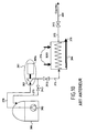
- the state of the technique is, so far, as illustrated on the Figure 10 , first use a low pressure pump 302 immersed in the storage tank 301 which feeds a high pressure pump 303 immersed in a buffer capacity 307.
- the liquid is sent to a exchanger-evaporator 304, is fed with water at room temperature and available in abundance (seawater, estuary, ...) when weather conditions allow, or is fed with heated water (which can be obtained by specific combustion or by the recovery of losses of a neighboring thermal machine), and which brings the high-pressure LNG to room temperature before injecting it into the pipeline 400.
- the 305a engines used to drive the high-pressure motor pumps 303 are generally squirrel cage asynchronous motors running at a fixed and limited speed: at most 3000 rpm for three-phase current at 50 Hz and 3600 rpm for 60 Hz current. This technology leads to motor pumps. 303 with a large number of floors and large dimensions. In particular, such a technology will be a handicap for all offshore applications. Furthermore, the high pressure pumps 303 require a large amount of electrical energy which represents the largest financial item in the cost of operating the terminal.
- the Figure 10 presents a schematic diagram of the regasification process on a LNG terminal according to the prior art.
- the high pressure pump functions, as well as reheat / vaporization are grouped geographically on the terminal, and the number of transfer lines 370, 371, 372 is limited to one or two.
- the diagram represents only one piece of equipment per function and, moreover, the equipment of regulation, regulation and control do not appear either for easier comprehension. Only three types of valves are shown in the diagram.
- a 3V1 valve is located at the discharge of an HP 303 pump and a 3V2 valve is located at the inlet of the pipeline 400 acting as a discharger.
- the valves 3V1 and 3V2 participate in the adjustment of the flow rate and the emission pressure to the pipeline 400 on the lines 371, 372.
- valve 3V2 is in series with a stop valve or a check valve. return.
- a 3V3 valve recirculates LNG at low pressure to the tank 301 or a specific circuit via a line 373 to carry out the cold-start before starting the HP 303 pumps.
- the LNG is extracted from the tank 301 by a low-level pump.
- pressure 302 to the inlet of the high-pressure motor pumps 303 passes through an exchanger-evaporator 304 before being injected in gaseous form under pressure into the gas pipeline network 400. Water is introduced into the exchanger-evaporator 304 via a circuit 374 and is evacuated by a discharge circuit 375.
- the US Patent 5,678,411 describes a more precise application with a turbopump used in a device implementing evaporation natural gas in a heat exchanger fed with seawater, the turbine providing the driving power to the pump by the partial expansion of the gas vaporized by the exchanger.
- the enthalpy of the gas is just sufficient to allow an outlet pressure of 3 to 6 MPa. This pressure proves to be insufficient for many pipelines, and in particular for the European network whose supply pressure is close to 8 MPa, and can reach 10 MPa for certain applications.
- the enthalpy difference in an adiabatic expansion between 15 MPa, 273 K and 10 MPa is less than the compression power of the liquid between 0.5 MPa and 15 MPa.
- the US Patent 5,649,425 uses the heating of natural gas upstream of the turbine beyond the ambient temperature by a natural air-gas burner. This heating makes it possible to recover more enthalpy in the turbine and thus to compensate the pumping energy, but in return the burned gas represents an economic loss as well as the electric power used in a high pressure motor pump.
- This US Patent 5,649,425 proposes a second solution: the pump is a two-stage pump (or two groups of stages) the total flow of LNG passing in the first pump stage and a fraction of the main flow then being brought to a higher pressure, then heated and vaporized in the exchanger to operate the turbine.
- the flow of LNG leaving the first stage is used for ancillary functions, such as supplying a thermal power station for example.
- This solution can only be used if the LNG terminal is coupled to a thermal power station or if it can deliver natural gas at two pressure levels.
- the invention aims to remedy the aforementioned drawbacks and to reduce or even cancel the power consumption of the LNG regasification terminal.
- the invention thus aims to provide global and economically profitable solutions to LNG regasification terminals by allowing them to reduce or cancel their power consumption, or even become electricity producers while overcoming the disadvantages of the aforementioned existing systems.
- the invention is also well suited to particular configurations where the terminal is coupled to a power plant using thermal machines, in which the thermal losses of the plant are recovered and transferred to the exchanger-evaporators of the terminal.
- the invention is also applicable to any industrial process involving compression and reheating at room temperature of a liquefied gas.
- a compression-evaporation system for liquefied gas contained in a tank, comprising sampling and pumping means for extracting and discharging the liquefied gas under low pressure out of the tank, high pressure pumping means, evaporation means by heat exchange with a liquid fluid and means for conditioning and transfer to a pipeline, characterized in that it comprises at least one turbomachine constituted by a motor-turbopump comprising a rotating assembly to high bending stiffness on the same shaft line, with at least one high pressure pump comprising an axial suction stage and at least one centrifugal wheel, a turbine and a central electric machine that can be used in engine or generator mode and located between the high pressure pump and the turbine, this motor-turbopump being compactly arranged inside a rigid casing having only static seals with the surrounding medium, the rotating assembly of the motor-turbopump being adapted to have a high rotational speed greater than 12 000 rpm while remaining outside the ranges of excitation critical speeds of rotation, all the internal
- the rotational speed of the rotating assembly of the motor-turbopump is several tens of thousands of revolutions / minute and preferably between 20,000 and 40,000 rpm.
- a motor-turbo pump can be installed either directly on the transmission line of the terminal, or in a bypass between the output of a high-pressure motor pump and a heat exchanger. regasification.
- the system comprises a first exchanger-evaporator interposed between the high pressure pump and the turbine to provide compression / evaporation of the liquefied gas used as working fluid in the motor-turbopump.
- the evaporation means may comprise said first exchanger-evaporator interposed between the high pressure pump and the turbine and a second exchanger-evaporator disposed between the turbine and the pipeline to be supplied.
- the high-pressure pumping means exclusively comprise the high pressure pump of the turbopump that is mounted in series between the tank and the pipeline.
- the system may comprise a buffer capacity disposed at the inlet of the high pressure pump of the motor-turbopump.
- the system further comprises a condenser with a first circuit interposed between the output of the high pressure pump of the motor-turbopump and the first exchanger-evaporator and a second circuit interposed between the output of the turbine of the motor-turbopump and the buffer capacity, the second circuit being in heat exchange with the first circuit to reliquefier the gaseous fluid leaving said turbine.
- the high pressure pumping means comprise a motor pump whose input is connected to said sampling and pumping means, and whose output is connected to a first circuit of a condenser, the output of this first circuit being connected to the inlet of an exchanger-evaporator whose output is connected to said pipeline, said buffer capacity is connected in shunt at the output of said motor pump and the output of the turbine of the motor-turbopump is connected to the input of a second circuit of the condenser, the output of this second circuit being connected to said buffer capacity, the second circuit being in heat exchange with the first circuit to reliquefier the gaseous fluid leaving said turbine.
- the evaporation means by heat exchange with a liquid fluid comprise means for introducing and discharging a liquid fluid consisting of water whose temperature is at least equal to ambient temperature.
- the first exchanger-evaporator interposed between the high pressure pump and the turbine comprises means for introducing and discharging a liquid fluid consisting of water whose temperature is at least equal to room temperature.
- the motor-turbo pump comprises hydrostatic fluid bearings fed from the same fluid in the liquid and compressed state as the fluid available at the outlet of the high-pressure pump of the motor-turbopump.
- the motor-turbo pump may also comprise a hydraulic device for active balancing of the axial forces fed from the same fluid in the liquid and compressed state as the fluid available at the outlet of the high pressure pump of the motor-turbopump.
- the motor-turbo pump comprises an axial fluid stopper fed from the same fluid in the liquid and compressed state as the fluid available at the outlet of the high-pressure pump of the motor-turbopump.
- the motor-turbopump comprises active magnetic bearings and may also comprise a magnetic axial stop.
- the motor-turbo pump comprises high-speed ceramic ball bearings.
- the turbine of the motor-turbopump comprises a high-strength titanium alloy rotor TA6 V ELI type or TA5 E ELI or light alloy aluminum-lithium type.
- the high-pressure pump of the motor-turbo pump comprises one or more high-strength titanium alloy wheels of the TA6 V ELI or TA5 E ELI type or aluminum-lithium light alloy.
- the central electric machine of the motor-turbo pump comprises a rotor with permanent magnets, the power electronic circuits providing synchronous frequency power supply of the rotation speed and variable voltage in motor mode and converting the voltage variable created in fixed voltage rectified in generator mode.
- the central electric machine of the motor-turbo pump comprises a monoblock rotor with excitation coil fed by a rotating transformer and a bridge of rectifying diodes to regulate the excitation of the electric machine and to provide a constant voltage in generator mode and torque controlled in motor mode.
- the central electric machine of the motor-turbo pump comprises a squirrel-cage rotor, the power electronic circuits providing power at variable frequency and variable voltage in motor mode and converting the variable voltage created into fixed voltage rectified in generator mode.
- the invention which applies in particular to a regasification LNG terminal, aims at reducing or even canceling the power consumption of such a terminal and uses a specific turbine engine called a motor-turbopump (or MTP) which can apply to different cycles of energy recovery.
- MTP motor-turbopump
- the invention relates to a compression-evaporation system for liquefied gas, which further comprises conventional means used to ensure the compression / heating / evaporation of the liquefied gas, namely centrifugal withdrawal and pumping means for discharging the gas.
- the compression-evaporation system comprises complementary means which comprise at least one specific turbomachine, associated with one or more heat exchangers and with fluid and control equipment intended to ensure the recovery of energy in thermal or electrical form.
- the additional turbomachine may be installed either directly on the emission line of the terminal from the liquefied gas reservoir and leading to the gas pipeline, or in a bypass between the outlet of a high pressure pump and a regasification exchanger.
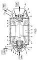
- the additional turbomachine or motor-turbopump integrates on the same line of trees a pump 26, an electric machine 11 that can be used in engine mode or in generator mode and that can be qualified alternately alternator, and a turbine 29, the machine 11 being arranged centrally between the pump 26 and the turbine 29 ( Figure 5 ).
- the motor-turbo pump is designed to run at a speed much higher than the speed of conventional high-pressure pumps.
- the rotational speed of a motor-turbopump is thus greater than 12,000 rpm and can advantageously go up to a few tens of thousands of revolutions per minute, typically between 20,000 and 40,000 rpm, this speed simply being to be outside the excitation ranges of the critical speeds of the motor-turbopump.
- the motor-turbo pump with its central electric machine 11 comprises a rotating assembly with high bending stiffness on the same shaft line and is compactly arranged inside a rigid housing 25 having only static seals with the surrounding environment ( Figure 5 ).
- All internal parts of the motor-turbopump are bathed by a common cryogenic fluid, in liquid or gaseous form, which is from the liquefied gas tank to evaporate or is of the same nature.
- the pump portion 26 comprises an axial suction stage 41 connected to a first centrifugal wheel 42.
- One or more centrifugal wheels may optionally be added to the first centrifugal wheel 42.
- An exhausted diffuser 43a and a volute 43b or an exhausted diffuser and a return channel provide the kinetic energy recovery of the fluid at the outlet of each centrifugal wheel. The successive centrifugal wheels are thus fed by the return channels.
- the pump 26 compresses the liquid gas introduced into the axial suction stage.
- the turbine 29 comprises a nozzle 46 for supplying pressurized gas, a bent distributor 47 ensuring the speed of the gas and a rotor 48 ensuring the conversion of the kinetic energy of the gases into mechanical energy.
- the turbine 29 may be for example of the axial type with total admission, in a single-stage or two-stage, supersonic, transonic or subsonic application.
- the turbine 29 may also be of the one-stage centripetal type.
- the central electric machine 11 which can still be called alternator, can operate in motor mode to provide the additional energy necessary for the proper operation of the pump 26.
- the electric machine 11 can still operate in generator mode to restore in the form of excess energy electricity in the turbine-pump balance.
- the electrical machine 11 is connected to electronic power circuits 12 which are connected to an electrical network 13 to drive the electric machine 11 in motor or generator mode ( Figures 1 to 4 and 9 ).
- the electric machine 11 comprises a stator magnetic circuit 22 and stator coils 23 ( Figures 5 and 6 ).
- the electric machine 11 comprises a rotor 20 whose peripheral speed is high, typically of the order of 250m / s.
- the rotor 20 must be made according to a technology compatible with such a rotational speed.
- the rotor 20 may for example be constituted by a squirrel cage laminated rotor.
- the electronic circuits 12 provide the power supply at variable frequency and voltage in motor mode and convert the variable voltage output of the machine into generator mode into fixed rectified voltage.
- the rotor 20 integral with a shaft 38 can advantageously be made, as shown in FIG. Figure 6 in the form of a one-piece high-strength steel rotor with an excitation coil 21 supplied via a rotating transformer 37 associated with rectifying diodes 30 so as to regulate the excitation of the machine and to provide a constant voltage in generator mode and a controlled torque in motor mode.
- the rotor 20 may also be permanent magnets for synchronous frequency supply of the rotational speed and variable voltage in motor mode and convert into generator mode the variable voltage from the machine in fixed voltage rectified.
- the rotor 48 of the turbine 29 and the impellers 41, 42 of the pump 26 are made of high-strength titanium alloy, for example of the TA6 V ELI or TA5 E ELI type, or of a light alloy, for example of the aluminum type. lithium.
- high-strength titanium alloy for example of the TA6 V ELI or TA5 E ELI type
- a light alloy for example of the aluminum type. lithium.
- the rotating assembly of the motor-turbopump can be supported by two hydrostatic fluid bearings 31 ( Figure 5 ).
- dynamic seals 28 can be arranged between the pump 26, the fluid bearing 31 located next to the pump 26, between this fluid bearing 31 located next to the pump 26 and the electric machine 11, between the electric machine 11 and the fluid bearing 31 located next to the turbine 29, and between the latter fluid bearing 31 located next to the turbine 29 and the turbine 29.
- the casing 25 of the motor-turbopump is compact, of high rigidity and has only static seals with the surrounding environment.
- This housing 25 is designed to minimize thermal leakage between the turbine 28 and the pump 26 while maintaining the alignment of the bearings.
- a rolling bearing 44 may be optionally provided to act as an emergency bearing as an axial rotary stop acting during the appearance of transients of the motor-turbopump, so as to ensure the recovery of efforts, especially when the speed rotation is too low for the pressures available in the motor-turbopump to balance the efforts, or in case of failure.
- the dynamic sealing barriers 28 may be composed of labyrinth or single floating ring joints, or of labyrinth or floating ring and leak recovery joint pairs to ensure the confinement of the fluids in each of the internal cavities of the motor-turbopump. .
- the fluid bearings 31 are fed with high pressure liquid fluid taken downstream of the last centrifugal wheel of the pump 26.
- the geometry of the last centrifugal wheel 42 of the pump 26 and the stator part vis-à-vis are designed to form one or two restrictions 49 to the passage of the fluid, these restrictions being of variable section according to the relative position between the rotor and the stator of the pump 26 and constituting an axial balancing device which makes it possible to modify the local pressure field and to cancel the resultant of the axial forces on the rotating assembly.
- the architecture and the internal ducts of the motor-turbopump are defined in such a way as to optimize the recirculations necessary for supplying the fluid bearings 31, as well as the axial balancing device. 49, while ensuring a cooling of the electric machine 11 and the fluid evacuations towards the pump inlet or the downstream circuit of the turbine 29.
- the active axial balancing device 49 can be replaced, if necessary, by a fluid abutment fed from the high pressure of the pump 26.
- the feed of the fluid bearings 31 and, if appropriate, of the fluid stop, can be made from an additional external source of the same fluid in the liquid and compressed state as the liquefied fluid from a main reservoir and intended for supply a pipeline.
- the additional external source may be, for example, a regasification LNG terminal which has pressurized liquid natural gas.
- the supply of the fluid bearings 31 from the additional external source can be carried out either permanently or during the only transient operating phases of the motor-turbopump.
- the electric machine 11 may be cooled for example by circulation of gas taken at the inlet of the turbine 29 and expanded to a pressure slightly greater than the pressure of the evacuation circuit, so as to maintain the fluid in a thermodynamic state gas or slightly diphasic. This choice is intended to minimize the losses by viscous friction in the air gap.
- the hydraulic balancing device 49 and the fluid bearings 31 are directly supplied with liquid natural gas taken from the high pressure portion of the pump 26 through internal recirculation.
- the fluid bearings 31 may also be permanently supplied with high pressure gaseous or liquid sources available on the terminal or simply before and during the transient conditions as long as the pressure delivered by the pump 26 is not sufficient.
- the architecture proposed for the motor-turbopump makes it possible to condition all its internal volumes with natural gas in liquid or vapor form and to present only static seals vis-à-vis the external environment.
- the pump 26, the fluid bearings 31 and possibly the electric machine 11 are in a liquid environment, the other internal volumes being in a gaseous environment.
- the confinement of each cavity presenting a pressure and a quality of fluid different from adjacent cavities is provided by dynamic seals 28 made by labyrinth type joints or floating rings, to minimize leakage and ensuring the machine the absence of wear by rubbing contact.
- the dynamic seals 28 are mounted as needed alone or in pairs, and in this second case, the low pressure leaks are collected between each pair of seals, and evacuated when possible downstream of the turbine 29, or reincorporated at the inlet of the pump 26.
- the electric machine 11 can be cooled by fluid circulation in the liquid phase.
- the electric machine operating in a thermal environment to less than 150 K sees its improved performance.
- the stator of the electric machine 11 is in this case jacketed so as to minimize friction losses of the liquid in the air gap.
- the hydrostatic fluid bearings 31 may be replaced by active magnetic bearings. Such bearings are completely insensitive to wear and thus give the motor-turbopump a very long life.
- the hydraulic device 49 balancing the axial forces exerted on the rotating assembly of the motor-turbopump can also be replaced by an active axial magnetic stop.
- the set of active magnetic bearings and the electric machine 11 is conditioned in natural gas in the liquid or gaseous state, and the seals 28 are reduced to two located on the one hand between the pump 26 and the bearing located next to the pump 26 and on the other hand between the turbine 29 and the bearing located next to the turbine 29.
- the pump 26 is used to compress a liquid fluid at low temperature, such as liquefied natural gas, and the turbine 29 ensures the supply of mechanical energy to the pump 26 by expansion of the same fluid in the gaseous state.
- a liquid fluid at low temperature such as liquefied natural gas
- the electric machine 11 provides the additional mechanical energy to the pump 26 if the turbine 29 is not sufficient or on the contrary discharges the excess energy from the turbine 29 in the form of electric power generation.
- the electric machine 11 is driven in motor or generator mode by electronic power circuits 12 connected to an electrical network 13 of frequency f and rated voltage U determined.
- the electronic power circuits 12 may comprise a current rectifier 51, a voltage converter 52 and an inverter 53 interposed between the electric machine 11 and the power supply network 13.
- the set of circuits 12 makes it possible to manage the transfer of current in both directions, from the motor-turbopump to the network 13 in the generator mode and from the network 13 to the motor-turbopump in the engine mode.
- Circulation circuits 55 for controlling the torque and the speed of rotation of the electrical machine 11 are connected to the latter, to the rectifier 51 and to the voltage converter 52.
- the power electronic circuits 12 also comprise control circuits 54 of various types. valves associated with the motor-turbopump.
- the steering of the motor-turbopump can be provided judiciously in speed regardless of the energy balance between the pump 26 and the turbine 29: when this balance is in favor of the turbine 29, the electronic circuits retransmit the excess current to the local network 13 by adapting its characteristics of voltage and frequency, and conversely they provide the good frequency characteristics, voltage to the motor 11 in case of power deficit between the need of the pump 26 and the performance of the turbine 29.
- the device allows to perfectly regulate the starting or stopping transients of the motor-turbopump and to ensure the proper functioning of the system.
- the electronic circuits are adapted to the particular technology adopted for the electric machine 11.
- the electronic circuits can be very simple. Voltage constant delivered at the output of the electrical machine 11 makes it possible to eliminate the voltage conversion module 52.
- the voltage conversion module 52 is necessary and a rotor position sensor is required to control the phasing in the motor or generator mode.
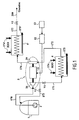
- the only high pressure pump used is constituted by the high pressure pump 26 of the motor-turbopump 5 as described above.
- the pump 26 is designed to deliver a pressure greater than the need necessary to supply the pipeline 200.
- the gas from the tank 1 can thus, after vaporization and reheating at room temperature, in a first exchanger-evaporator 4 , being expanded in the turbine 29 to the inlet pressure in the pipeline 200, thereby producing mechanical energy that reduces the energy that must provide the electric motor 11 to drive the pump 26, the variation of enthalpy per unit of pressure being in the gaseous state greater than that of the liquid state.
- the gas leaving the turbine 29 being at a temperature below ambient, it must undergo additional heating by crossing a second heat exchanger 4 'operating with water at room temperature (sea water or river ), introduced by a circuit 174 'and discharged by a circuit 175'.
- a valve V3 is located on a cooling line 173 disposed in shunt at the outlet of the high pressure pump 26 and leading back to the tank 1.
- the motor-turbopump 5 is systematically associated with a first exchanger-evaporator 4 located upstream of the turbine 29 and downstream of the pump 26, and where appropriate also with a second exchanger-evaporator 4 'located downstream of the turbine 29.
- the embodiment of the Figure 1 avoids the introduction of a complex system of flow distribution to each turbine 29 of a motor-turbopump 5. It is not necessary to provide additional equipment for cold or recycling for the pump high pressure 26 other than existing ones. On the contrary, the presence of the electronic power control circuits 12 makes it possible to regulate the speed of the motor-turbo pump 5, so that, if appropriate, the control valve V1 situated at the discharge of the high-pressure pump 26 on the line 171 could to be deleted.
- the Figure 7 shows the arrangement of the various components and the routing of the flows inside a motor-turbopump 5 implemented as part of the application illustrated on the Figure 1 .
- reference numeral 60 denotes a feed line of the fluid bearings 31 from natural gas in the liquid state taken at the outlet of the last centrifugal wheel of the pump 26 or, if appropriate, directly taken from a high pressure liquid line of the terminal where the reservoir 1 is located.
- the feed rate of the fluid bearings 31 is determined by calibrated orifices 64.
- the liquid natural gas is collected at low pressure at the outlet of the fluid bearings 31 and reincorporated at the inlet of the pump. 26 by line 61.
- the cooling rate of the electrical machine 11 is taken at the inlet of the turbine 29, expanded through a calibrated orifice 64 'and undergoes a complementary expansion through a second calibrated orifice 64 "located at the outlet of the electric machine 11 before being reincorporated by the line 62a at the inlet of the pump 26.
- the supply of the fluid bearings 31 and the cooling of the electric machine 11 can be made from circulation ducts drilled in the crankcases of the motor-turbopump or by external pipes.
- this device When a hydraulic device 49 for balancing the axial forces exerted on the rotating assembly of the motor-turbopump 5 is used, this device is equipped with devices that serve as a calibration for the flow circulating on the back of the plate. balancing and to adapt the pressure field to cancel the resultant efforts.
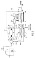
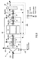
- the Figure 2 shows another example of energy recovery cycle in which, as in the cycle of the Figure 1 , a conventional high pressure motor pump 303 of a terminal (like that of the Figure 10 ) is replaced by a motor-turbopump 5.
- the outlet pressure of the pump high pressure 26 of the motor-turbopump 5 is not increased, however.
- a fraction of the flow of fluid passing through the pump 26 is taken at the outlet of the exchanger-evaporator 4 and derived by a line 172 equipped with an isolation valve V4, to the turbine 29 to be relaxed at low pressure in this turbine 29 before being discharged through a line 176 to pass through another heat exchanger 6 acting as a condenser.
- the reliqued fluid coming from the circuit 6b of the exchanger-condenser 6 is reinjected in liquid form, by a line 182 equipped with an isolation valve V5, in a capacity 7 intended to eliminate the bubbles that can remain in the condensate, and located at the inlet of the high pressure pump 26.
- the output stream of the circuit 6a of the condenser 6 is applied via a line 178 equipped with an isolation valve V6 at the inlet of the heat exchanger 4 to water at ambient temperature (introduced by the circuit 174 and discharged by the circuit 175).
- the flow of liquid flowing in the circuit 6a of the condenser 6 acts as a cold source and supplies the circuit 6b the frigories necessary for the condensation of the fluid flowing in the line 176 at the outlet of the turbine 29.
- a line 177 equipped with a cooling valve V3b supplies a cooling circuit.
- the outlet of the exchanger-evaporator 4 is connected by a line 179 equipped with an isolation valve V2 to a pipeline 200.
- valves V4, V5 ensure the isolation of the turbine circuit 29-condenser 6.
- the valve V4 located on the line 172 further allows to regulate the flow of fluid derived to the turbine 29.
- the cold fluid side of the condenser 6 must be previously cooled to the temperature of the liquid natural gas.
- the cooling of the HP pump portion 26 is completed by a liquid flow established by the opening of the valve V3b, the valve V6 then being closed to isolate the evaporator 4 (cf. Figure 2 ).
- the start of the motor-turbo pump 5 is provided by the alternator 11 operating in engine mode and controlled by the electronic circuit 12, which ensures a gradual increase in pressure.
- the valves V4 and V5 are progressively opened to drive the turbine 29.
- the regulation of the flow derived to the turbine 29 is provided by the valve V4 which also serves as a control valve. During a shutdown, the valve V4 can be closed to stop the supply of the turbine 29 and the motor 11 can then be stopped.
- the motor-turbopump 5 / condenser 6 unit can advantageously be grouped together on the same platform so as to minimize the liquid transfer lines and simplify the insulation of the cold zones (thermal insulators or cold boxes).
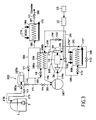
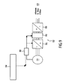
- the Figure 3 illustrates another example of a cycle using a motor-turbopump 105 according to the invention.
- a conventional high pressure pump 103 similar to the motor pump 303 of the Figure 10 , with a high pressure pump 103a driven by a motor 103b can be a conventional electric motor.
- a line 185 also equipped with a control valve V8 is connected to a circuit 106a of a condenser 106, the output of the circuit 106a being connected at the inlet line 186 of the exchanger-evaporator 104.
- Valves V7 and V8 serve to regulate the flow of liquefied gas derivative to the circuit 106a of the condenser 106.
- the valve V8 also isolates the condenser 106 of the transmission circuit of the terminal and is used to start the energy recovery loop. If the terminal does not accept additional pressure drop on the transmission line 171, it is possible to replace the valve V7 by a circulation pump installed on the branch line 185 to the condenser 106, the flow control derived being ensured in this case by controlling the valve V8 and / or the bypass pump.
- the energy recovery loop comprises a motor-turbopump 105 of the type described above, an exchanger-evaporator 108 using water at room temperature or reheated, the circuit 106b or "hot" compartment of the condenser 106 as well as a buffer capacity 107 located upstream of the pump 26, the fluid transfer pipes and the various valves intended to ensure the proper operation of the loop.
- the recovery loop operates in a closed cycle.
- the fluid introduced into the energy recovery loop is derived from the transmission line of the terminal, downstream of the high-pressure pump 103a, via a line 183 equipped with a valve V9 which supplies the capacity 107.
- the exchanger-evaporator 108 has a water supply circuit 174 "at room temperature or slightly heated and provided by a co-generation source available nearby, the water being discharged by a circuit 175".
- the fluid supplied by the capacitor 107 through the line 170b is admitted to the liquid at the inlet of the pump 26 of the motor-turbopump 105, is pressurized by this pump 26, then vaporized and reheated in the water heat exchanger 108 until at room temperature or at a higher temperature when using heated water
- the fluid flowing through the lines 192, 193 is then expanded in the turbine 29 where it transfers a mechanical energy greater than the energy required for the pumping.
- 29 through lines 176, 195 is then liquefied at low pressure in the circuit 106b of the condenser 106, and recycled by a line 196 in the capacity 107 placed at the inlet of the pump 26.
- the excess of mechanical energy is converted into electricity by the electric machine 11 which then operates in generator mode and can be supplied to the terminal or the local electrical network.
- the next step is to fill the energy recovery loop by opening for natural gas the valve V9, the valve V11 located on the line 189 at the inlet of the exchanger 108 being closed and the valve V10 located on the line 191 being open.
- the evaporations resulting from the cooling are discharged to the cold collection circuit of the terminal, the valve V9 being closed if the pressure in the capacity becomes too great.
- the motor-turbo pump 105 can be activated in motor / pumping at a very low speed so as to establish a circulation of liquid in the pump. During this period, the leaks of the fluid bearings 31 are collected and discharged through a three-way valve V15 (cf.
- the third step consists in starting the motor-turbo pump 105 in engine mode thanks to the electronic circuits 12, the valve V11 being open and the valve V10 closed to supply the turbine 29 which progressively takes over the engine, and then supplies excess energy. to the needs of the pump 26 and allows to switch to generator mode.
- the energy recovery loop has on a line 190 a bypass valve V12 of the exchanger-evaporator 108 which makes it possible to adjust the temperature at the inlet of the turbine 29 and consequently the temperature at the outlet of the condenser 106, and a bypass valve V13 of the turbine 29 which, by drifting on a line 194 all or part of the flow, can ensure the emergency stop of the motor-turbopump 105 in case of failure of the generator or its electronics, and if necessary the speed regulation of the motor-turbopump 105.
- the electronic power circuits can also provide speed regulation of the motor-turbopump 105, without prejudice to the performance because in this case all the pumped flow passes through the turbine 29.
- Stopping the loop is effected by closing the valve V11 and opening the valve V10, the turbine 29 of the motor-turbopump 105 being fed only by the gas volume contained in the exchanger-evaporator 108 and the upstream line stops gradually. If an emergency stop is required, it is activated by opening the valve V13.
- the part 26 of the motor-turbopump 105, as well as the buffer capacity 107, the condenser 106 and the liquid lines are packaged in a cold box or insulated to avoid heat losses and allow the recovery loop to have phases of waiting filled with fluid, but without operation.
- the capacity 107, the motor-turbopump 105, the condenser 106 and the winnowing equipment can be integrated on a common platform.
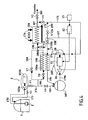
- the Figure 4 illustrates yet another example of a cycle using a motor-turbopump 105 according to the invention.
- part of the liquefied gas emitted by the terminal from a tank 1 is taken at the outlet of a traditional high pressure pump 103a and upstream of a conventional evaporator 104 to be diverted to a condenser 106 to act as a cold source of an open energy recovery cycle, using the same natural gas as that of the terminal.
- a fraction of the natural gas is taken at the outlet of the conventional exchanger-evaporator 104 of a terminal to be expanded in the turbine 29 of the motor-turbopump 105 where the expanded gas then passes through the circuit 106b of the condenser 106 to be liquefied then, after being reintroduced in the capacity 107, to circulate in the line 170b, be pressurized in liquid form by the pump 26 of the motor-turbopump 105 and then be reinjected by the line 200 and the isolation valve V14, either in the main flow of the terminal at the inlet of the exchanger-evaporator 104, or possibly in the flow derived from the pump 103a supplying as a cold source the circuit 106a of the condenser 106.
- the pump 26 of the motor-turbopump 105 must provide the same overpressure as the high-pressure pumps 103a of the terminal.
- the solution presented on the Figure 4 differs from that of Figure 3 by the use of the exchangers-evaporators 104 of the terminal for the energy recovery loop. It can be easily applied to an existing terminal by creating in addition to previous modifications on the high pressure line (bypass, valves V7, V8) two additional interfaces, the first upstream of the exchangers-evaporators 104 to reintroduce the liquid natural gas from the motor-turbopump 105, and the second downstream of the same evaporators 104 to supply the turbine 29 of the motor-turbopump 105.
- the recovery loop then comprises the condenser 106, the motor-turbopump 105 and the upstream capacity 107 and the pipes and valves defined on the Figure 4 , justified by the implementation defined below.
- the first step is to activate the valves V7, V8 for supplying the circuit 106a of the condenser 106 in cold fluid.
- the filling of the buffer capacity circuit 107, the motor-turbopump 105, the pump part 103a, the circuit 106b of the condenser 106 is carried out by opening the valve V9, the valves V4, V14 being closed and the valve V10b on the line 198 being opened.
- the start-up of the alternator 11 at very low speed in motor mode makes it possible to use the pump 26 as a fluid circulator and thus to ensure that the "liquid" portion of the loop is cold.
- the leaks of the fluid bearings 31 are as previously evacuated through the valve V15 to a low-pressure collection circuit of the terminal.
- valves V10b and V9 are closed, the valve V4 on the inlet of the turbine 29 is opened gradually , and the electric machine 11 is activated in engine mode simultaneously to start the pump 26.
- the electric machine 11 goes into generator mode as soon as the power provided by the turbine 29 allows it, and the valve V14 is open when the pressure at the outlet of the pump 26 reaches the existing pressure at the inlet of the evaporators 104 of the terminal.
- the temperature at the inlet of the turbine 29 can be adjusted by adjusting the opening of the valve V12b placed on a line 199.
- the rotational speed of the motor-turbopump 105 is regulated by the electronic control circuits.
- Stopping the recovery loop is obtained by closing the turbine supply valve V4 29 and the valve V14 to prevent the reverse circulation of high pressure liquid in the pump 26 through the line 197. Unlike the solution previous, there is no large gaseous volume trapped upstream of the turbine 29 as soon as the valve V4 is closed and it is not necessary to bypass the turbine 29 during an emergency stop.
- the buffer capacity 107 is equipped with valve systems for draining the loop and evacuating excess gas to the collection circuits of the terminal.
- the exchanger-evaporators may be, for example, water-trickle exchangers, or else of the tube / shell or coil type in a tank of heated water.
- the condenser 106 is typically a plate or tube / shell heat exchanger.
- the invention applies to systems having a larger number of components.
- the regasification terminals are arranged on the basis of a grouping of the different functions with HP motor pump batteries connected by one or two high-pressure lines to exchanger-evaporator batteries.
- the number of pump and evaporator equipment used is a function of the emission rate requested from the terminal, and the control valves located on the discharge of the HP pumps, as well as those which are installed in Downstream of the evaporators ensure the adjustment of the flow and the pressure at the inlet of the pipeline.
- the start-up of an HP motor pump imposes a particular sequence. Firstly, the motor pump must be cooled to the temperature of the liquid gas by circulating liquid natural gas under low pressure, then recovered in a specific collection circuit, to avoid the presence of gaseous bubbles in the liquid and the cavitation of the liquid. pump in operation. It is this cold-start sequence that uses a 3V3 purge valve (cf. Figure 10 ). During the start-up then, and to avoid a sudden rise in pressure of the pumped fluid and the presence of water hammer, a part of the flow is derived at the discharge of the pump and recycled to another compatible collecting circuit of the higher pressure . In the context of the present invention, a purge valve 3V2b, associated with a cooling circuit, is also implemented with a motor-turbopump 5 or 105 as has been mentioned in the various examples of the Figures 1 to 4 .
Landscapes
- Engineering & Computer Science (AREA)
- Mechanical Engineering (AREA)
- General Engineering & Computer Science (AREA)
- Structures Of Non-Positive Displacement Pumps (AREA)
- Filling Or Discharging Of Gas Storage Vessels (AREA)
Applications Claiming Priority (1)
| Application Number | Priority Date | Filing Date | Title |
|---|---|---|---|
| FR0413486A FR2879720B1 (fr) | 2004-12-17 | 2004-12-17 | Systeme de compression-evaporation pour gaz liquefie |
Publications (3)
| Publication Number | Publication Date |
|---|---|
| EP1672270A2 EP1672270A2 (fr) | 2006-06-21 |
| EP1672270A3 EP1672270A3 (fr) | 2006-09-27 |
| EP1672270B1 true EP1672270B1 (fr) | 2008-10-08 |
Family
ID=35395413
Family Applications (1)
| Application Number | Title | Priority Date | Filing Date |
|---|---|---|---|
| EP05292705A Expired - Lifetime EP1672270B1 (fr) | 2004-12-17 | 2005-12-15 | Système de compression-évaporation pour gaz liquéfié |
Country Status (6)
| Country | Link |
|---|---|
| US (1) | US7406830B2 (enExample) |
| EP (1) | EP1672270B1 (enExample) |
| JP (1) | JP2006194440A (enExample) |
| KR (1) | KR20060069346A (enExample) |
| ES (1) | ES2314599T3 (enExample) |
| FR (1) | FR2879720B1 (enExample) |
Families Citing this family (75)
| Publication number | Priority date | Publication date | Assignee | Title |
|---|---|---|---|---|
| DE102005038273A1 (de) * | 2005-08-02 | 2007-02-08 | Linde Ag | Maschine mit einem drehbaren Rotor |
| JP2007211597A (ja) * | 2006-02-07 | 2007-08-23 | Hitachi Ltd | プラント設備 |
| FI122435B (fi) | 2006-10-18 | 2012-01-31 | Savonia Power Oy | Höyryvoimalaitos |
| US8128021B2 (en) | 2008-06-02 | 2012-03-06 | United Technologies Corporation | Engine mount system for a turbofan gas turbine engine |
| US20140174056A1 (en) | 2008-06-02 | 2014-06-26 | United Technologies Corporation | Gas turbine engine with low stage count low pressure turbine |
| US8616323B1 (en) | 2009-03-11 | 2013-12-31 | Echogen Power Systems | Hybrid power systems |
| EP2419621A4 (en) | 2009-04-17 | 2015-03-04 | Echogen Power Systems | SYSTEM AND METHOD FOR MANAGING HEAT PROBLEMS IN GAS TURBINE ENGINES |
| EP2446122B1 (en) | 2009-06-22 | 2017-08-16 | Echogen Power Systems, Inc. | System and method for managing thermal issues in one or more industrial processes |
| WO2011017476A1 (en) | 2009-08-04 | 2011-02-10 | Echogen Power Systems Inc. | Heat pump with integral solar collector |
| WO2011032958A1 (en) * | 2009-09-17 | 2011-03-24 | Shell Internationale Research Maatschappij B.V. | Off-shore structure comprising two power systems and method of powering the same |
| US8869531B2 (en) | 2009-09-17 | 2014-10-28 | Echogen Power Systems, Llc | Heat engines with cascade cycles |
| US8813497B2 (en) | 2009-09-17 | 2014-08-26 | Echogen Power Systems, Llc | Automated mass management control |
| US8613195B2 (en) | 2009-09-17 | 2013-12-24 | Echogen Power Systems, Llc | Heat engine and heat to electricity systems and methods with working fluid mass management control |
| US9115605B2 (en) | 2009-09-17 | 2015-08-25 | Echogen Power Systems, Llc | Thermal energy conversion device |
| KR101121721B1 (ko) * | 2010-01-28 | 2012-02-28 | 에스티엑스조선해양 주식회사 | 부유식 엘엔지 재기화설비 |
| AT509334B1 (de) * | 2010-07-09 | 2011-08-15 | Lo Solutions Gmbh | Verfahren und vorrichtung zur bereitstellung von elektrischer und thermischer energie, insbesondere in einer hafenanlage |
| US8963354B2 (en) * | 2010-09-13 | 2015-02-24 | Ebara International Corporation | Power recovery system using a rankine power cycle incorporating a two-phase liquid-vapor expander with electric generator |
| US8783034B2 (en) | 2011-11-07 | 2014-07-22 | Echogen Power Systems, Llc | Hot day cycle |
| US8616001B2 (en) | 2010-11-29 | 2013-12-31 | Echogen Power Systems, Llc | Driven starter pump and start sequence |
| US8857186B2 (en) | 2010-11-29 | 2014-10-14 | Echogen Power Systems, L.L.C. | Heat engine cycles for high ambient conditions |
| US8542085B2 (en) * | 2011-02-28 | 2013-09-24 | GM Global Technology Operations LLC | High frequency rotary transformer for synchronous electrical machines |
| JP5999874B2 (ja) * | 2011-02-28 | 2016-09-28 | 三菱重工業株式会社 | 液化ガスの再ガス化装置および再ガス化ガス製造方法 |
| US9239012B2 (en) | 2011-06-08 | 2016-01-19 | United Technologies Corporation | Flexible support structure for a geared architecture gas turbine engine |
| US9523422B2 (en) | 2011-06-08 | 2016-12-20 | United Technologies Corporation | Flexible support structure for a geared architecture gas turbine engine |
| US9631558B2 (en) | 2012-01-03 | 2017-04-25 | United Technologies Corporation | Geared architecture for high speed and small volume fan drive turbine |
| WO2013055391A1 (en) | 2011-10-03 | 2013-04-18 | Echogen Power Systems, Llc | Carbon dioxide refrigeration cycle |
| US10287914B2 (en) | 2012-01-31 | 2019-05-14 | United Technologies Corporation | Gas turbine engine with high speed low pressure turbine section and bearing support features |
| JP5645858B2 (ja) * | 2012-02-27 | 2014-12-24 | 株式会社日立製作所 | 永久磁石式ポンプ電動機 |
| US20130219907A1 (en) * | 2012-02-29 | 2013-08-29 | Frederick M. Schwarz | Geared turbofan architecture for improved thrust density |
| US10125693B2 (en) | 2012-04-02 | 2018-11-13 | United Technologies Corporation | Geared turbofan engine with power density range |
| KR101648856B1 (ko) * | 2012-05-16 | 2016-08-17 | 티지이 마린 개스 엔지니어링 게엠베하 | 가스 공급 장치 및 가스 공급 장치를 사용하는 방법 |
| US8572943B1 (en) | 2012-05-31 | 2013-11-05 | United Technologies Corporation | Fundamental gear system architecture |
| US20150308351A1 (en) | 2012-05-31 | 2015-10-29 | United Technologies Corporation | Fundamental gear system architecture |
| US8756908B2 (en) | 2012-05-31 | 2014-06-24 | United Technologies Corporation | Fundamental gear system architecture |
| US8742604B2 (en) * | 2012-06-06 | 2014-06-03 | Energy Recovery, Inc. | Systems and methods for combined flow control and electricity generation |
| CA2882290A1 (en) | 2012-08-20 | 2014-02-27 | Echogen Power Systems, L.L.C. | Supercritical working fluid circuit with a turbo pump and a start pump in series configuration |
| FR2994731B1 (fr) * | 2012-08-22 | 2015-03-20 | Snecma | Procede de mise en froid |
| US9118226B2 (en) | 2012-10-12 | 2015-08-25 | Echogen Power Systems, Llc | Heat engine system with a supercritical working fluid and processes thereof |
| US9341084B2 (en) | 2012-10-12 | 2016-05-17 | Echogen Power Systems, Llc | Supercritical carbon dioxide power cycle for waste heat recovery |
| CN102996469B (zh) * | 2012-12-24 | 2015-09-30 | 成都安迪生测量有限公司 | 一种多头螺旋密封的低温潜液泵 |
| JP2016510376A (ja) | 2012-12-28 | 2016-04-07 | ゼネラル・エレクトリック・カンパニイ | 航空機において燃料を供給するための極低温燃料システム及び方法 |
| DE102013200572A1 (de) * | 2013-01-16 | 2014-07-17 | Siemens Aktiengesellschaft | Vorrichtung zur Regasifizierung von Flüssigerdgas und zugehöriges Verfahren |
| WO2014117068A1 (en) | 2013-01-28 | 2014-07-31 | Echogen Power Systems, L.L.C. | Methods for reducing wear on components of a heat engine system at startup |
| EP2948649B8 (en) | 2013-01-28 | 2021-02-24 | Echogen Power Systems (Delaware), Inc | Process for controlling a power turbine throttle valve during a supercritical carbon dioxide rankine cycle |
| CA2903784C (en) | 2013-03-04 | 2021-03-16 | Echogen Power Systems, L.L.C. | Heat engine systems with high net power supercritical carbon dioxide circuits |
| US20160017759A1 (en) * | 2013-03-14 | 2016-01-21 | Echogen Power Systems, L.L.C. | Controlling turbopump thrust in a heat engine system |
| FR3005687B1 (fr) | 2013-05-20 | 2017-09-15 | Snecma | Turbopompe avec systeme anti-vibrations |
| KR101525679B1 (ko) * | 2013-10-22 | 2015-06-03 | 현대중공업 주식회사 | 액화가스 처리 시스템 |
| WO2016073252A1 (en) * | 2014-11-03 | 2016-05-12 | Echogen Power Systems, L.L.C. | Active thrust management of a turbopump within a supercritical working fluid circuit in a heat engine system |
| RU2676509C1 (ru) * | 2015-01-30 | 2018-12-29 | Дэу Шипбилдинг Энд Марин Инджиниринг Ко., Лтд. | Система и способ подачи топлива к судовому двигателю |
| US10167732B2 (en) * | 2015-04-24 | 2019-01-01 | Hamilton Sundstrand Corporation | Passive overspeed controlled turbo pump assembly |
| CN105240127A (zh) * | 2015-10-26 | 2016-01-13 | 成都华气厚普机电设备股份有限公司 | 一种发动机试车平台燃气供气控制系统 |
| PL3455542T3 (pl) * | 2016-05-10 | 2020-11-30 | Wärtsilä Finland Oy | Układ zbiornika |
| WO2017194819A1 (en) | 2016-05-10 | 2017-11-16 | Wärtsilä Finland Oy | Tank arrangement |
| JP6586533B2 (ja) | 2016-05-10 | 2019-10-02 | ワルトシラ フィンランド オサケユキチュア | バイローブ又はマルチローブタンク |
| JP6845675B2 (ja) * | 2016-12-08 | 2021-03-24 | 川崎重工業株式会社 | 原料ガス液化装置及びその制御方法 |
| US10712235B2 (en) * | 2017-04-24 | 2020-07-14 | Energy Recovery, Inc. | System and method for monitoring operating condition in a hydraulic turbocharger |
| CN108826013A (zh) * | 2018-06-27 | 2018-11-16 | 山东交通学院 | 一种液化气船卸货再气化系统 |
| US10883388B2 (en) | 2018-06-27 | 2021-01-05 | Echogen Power Systems Llc | Systems and methods for generating electricity via a pumped thermal energy storage system |
| KR102095957B1 (ko) * | 2018-09-20 | 2020-05-27 | 한국생산기술연구원 | 복합베어링, 그리고 이를 포함하는 발전기 및 발전 시스템 |
| CN109098809B (zh) * | 2018-10-11 | 2019-09-13 | 上海海事大学 | 一种带回热循环的利用lng冷能和工业废热的orc发电系统 |
| FR3089596B1 (fr) * | 2018-12-11 | 2021-03-19 | Air Liquide | Dispositif de support et conteneur de stockage de gaz liquéfié |
| CN109681777A (zh) * | 2019-01-08 | 2019-04-26 | 武希盛 | 一种低温液化气体无动力泵 |
| CN109723966B (zh) * | 2019-01-25 | 2020-10-23 | 太平洋海洋工程(舟山)有限公司 | 一种用于fsru的液态天然气再气化系统 |
| US11788190B2 (en) * | 2019-07-05 | 2023-10-17 | Asm Ip Holding B.V. | Liquid vaporizer |
| US11435120B2 (en) | 2020-05-05 | 2022-09-06 | Echogen Power Systems (Delaware), Inc. | Split expansion heat pump cycle |
| US11629638B2 (en) | 2020-12-09 | 2023-04-18 | Supercritical Storage Company, Inc. | Three reservoir electric thermal energy storage system |
| FR3120393B1 (fr) * | 2021-03-08 | 2025-10-10 | Safran | Système et procédé de conditionnement de carburant configuré pour alimenter un turbomoteur d’aéronef à partir de carburant issu d’un réservoir cryogénique |
| CN113389764B (zh) * | 2021-06-30 | 2022-11-15 | 四川航天烽火伺服控制技术有限公司 | 一种液压设备及其涡轮泵出口压力控制系统 |
| FR3128738B1 (fr) * | 2021-10-29 | 2024-01-12 | Safran | Système de conditionnement de carburant pour alimenter une turbomachine d’aéronef, procédé d’alimentation d’une turbomachine |
| CN115164104B (zh) * | 2022-05-11 | 2024-08-23 | 无锡恒大电子科技有限公司 | 一种高纯液化气体用集中控制输送装置 |
| CN115370586B (zh) * | 2022-08-19 | 2025-08-01 | 华为数字能源技术有限公司 | 一种压泵一体机及换热系统 |
| AU2024289421A1 (en) | 2023-02-07 | 2025-09-11 | Supercritical Storage Company, Inc. | Waste heat integration into pumped thermal energy storage |
| CN115823482B (zh) * | 2023-02-15 | 2023-05-12 | 济南华信流体控制有限公司 | 一种气体充装的管道系统 |
| CN116951306B (zh) * | 2023-07-26 | 2025-08-19 | 浙江理工大学 | 一种含压差发电的船舶lng供气系统 |
Family Cites Families (21)
| Publication number | Priority date | Publication date | Assignee | Title |
|---|---|---|---|---|
| BE551602A (enExample) | 1955-10-10 | |||
| US3068659A (en) | 1960-08-25 | 1962-12-18 | Conch Int Methane Ltd | Heating cold fluids with production of energy |
| GB1204119A (en) * | 1966-09-22 | 1970-09-03 | Nat Res Dev | Improvements in and relating to power generating systems |
| US3720057A (en) | 1971-04-15 | 1973-03-13 | Black Sivalls & Bryson Inc | Method of continuously vaporizing and superheating liquefied cryogenic fluid |
| CH569865A5 (en) | 1973-07-05 | 1975-11-28 | Sulzer Ag | Liquefied natural gas vaporisation process - uses heat exchange with working medium of closed-cycle gas turbine |
| GB1481682A (en) * | 1973-07-12 | 1977-08-03 | Nat Res Dev | Power systems |
| CH573571A5 (enExample) * | 1974-01-11 | 1976-03-15 | Sulzer Ag | |
| CH594131A5 (enExample) | 1975-07-09 | 1977-12-30 | Sulzer Ag | |
| CH588635A5 (enExample) | 1975-02-07 | 1977-06-15 | Sulzer Ag | |
| FR2318590A1 (fr) | 1975-07-25 | 1977-02-18 | Poilane Lionel | Nouveaux extraits de sons de cereales enrichis, leur procede de fabrication et adjuvants pour animaux a base desdits extraits |
| US4178761A (en) * | 1977-06-17 | 1979-12-18 | Schwartzman Everett H | Heat source and heat sink pumping system and method |
| US4444015A (en) | 1981-01-27 | 1984-04-24 | Chiyoda Chemical Engineering & Construction Co., Ltd. | Method for recovering power according to a cascaded Rankine cycle by gasifying liquefied natural gas and utilizing the cold potential |
| DE4025023A1 (de) * | 1990-08-07 | 1992-02-13 | Linde Ag | Verfahren zum verdampfen von fluessigem erdgas |
| EP0669466B1 (en) | 1994-02-23 | 2000-05-24 | Ebara Corporation | Turboexpander pump unit |
| US5678411A (en) | 1995-04-26 | 1997-10-21 | Ebara Corporation | Liquefied gas supply system |
| IT1283140B1 (it) * | 1996-07-11 | 1998-04-07 | Eniricerche Spa | Procedimento per rigassificare il gas naturale liquefatto |
| FI108067B (fi) * | 2000-09-13 | 2001-11-15 | High Speed Tech Ltd Oy | Turbogeneraattorin läpivientirakenne ja kiinnityslaippa |
| US20020112479A1 (en) * | 2001-01-09 | 2002-08-22 | Keefer Bowie G. | Power plant with energy recovery from fuel storage |
| US20030005698A1 (en) * | 2001-05-30 | 2003-01-09 | Conoco Inc. | LNG regassification process and system |
| US6827104B2 (en) * | 2001-10-24 | 2004-12-07 | Mcfarland Rory S. | Seal and valve systems and methods for use in expanders and compressors of energy conversion systems |
| AU2003260106A1 (en) * | 2002-08-30 | 2004-03-19 | Chart Inc. | Liquid and compressed natural gas dispensing system |
-
2004
- 2004-12-17 FR FR0413486A patent/FR2879720B1/fr not_active Expired - Lifetime
-
2005
- 2005-12-15 ES ES05292705T patent/ES2314599T3/es not_active Expired - Lifetime
- 2005-12-15 EP EP05292705A patent/EP1672270B1/fr not_active Expired - Lifetime
- 2005-12-16 JP JP2005363437A patent/JP2006194440A/ja not_active Ceased
- 2005-12-16 US US11/305,367 patent/US7406830B2/en not_active Expired - Fee Related
- 2005-12-17 KR KR1020050124897A patent/KR20060069346A/ko not_active Withdrawn
Also Published As
| Publication number | Publication date |
|---|---|
| US20060222523A1 (en) | 2006-10-05 |
| FR2879720B1 (fr) | 2007-04-06 |
| KR20060069346A (ko) | 2006-06-21 |
| ES2314599T3 (es) | 2009-03-16 |
| EP1672270A3 (fr) | 2006-09-27 |
| JP2006194440A (ja) | 2006-07-27 |
| FR2879720A1 (fr) | 2006-06-23 |
| EP1672270A2 (fr) | 2006-06-21 |
| US7406830B2 (en) | 2008-08-05 |
Similar Documents
| Publication | Publication Date | Title |
|---|---|---|
| EP1672270B1 (fr) | Système de compression-évaporation pour gaz liquéfié | |
| EP4355986B1 (fr) | Système et procédé de conditionnement de carburant configuré pour alimenter un turbomoteur d'aéronef à partir de carburant issu d'un réservoir cryogénique | |
| EP4158169B1 (fr) | Installation de réchauffement d'un carburant cryogénique | |
| FR3090756A1 (fr) | Dispositif de pompage, installation et procédé de fourniture d’hydrogène liquide | |
| WO2022023648A1 (fr) | Circuit d'alimentation en carburant de turbomachine cryogenique aeronautique et procede associe | |
| EP3510257A1 (fr) | Système mécanique de production d'énergie mécanique à partir d'azote liquide, et procédé correspondant | |
| WO2013057427A1 (fr) | Stockage adiabatique ameliore d'energie sous forme de chaleur et d'air comprime. | |
| FR2640322A1 (fr) | Moteur-fusee ou moteur combine pour vehicule spatial a circuit hydraulique auxiliaire essentiellement ferme | |
| EP3899351B1 (fr) | Poste de détente d'un gaz et de compression d'un fluide | |
| WO2022189154A1 (fr) | Système et procédé de conditionnement de carburant configuré pour alimenter un turbomoteur d'aéronef à partir de carburant issu d'un réservoir cryogénique | |
| EP3698048B1 (fr) | Dispositif et procédé de compression et machine de réfrigération | |
| EP3438422B1 (fr) | Dispositif et procédé de régulation de la charge fluidique en circulation dans un système basé sur un cycle de rankine | |
| WO2019077213A1 (fr) | Dispositif et procédé de compression | |
| EP4453404A1 (fr) | Systeme et procede de conditionnement de carburant pour moteur aerobie a hydrogene | |
| EP4222366A1 (fr) | Système d'alimentation en gaz pour appareils consommateurs de gaz à haute et basse pression | |
| EP4403769A1 (fr) | Dispositif et procédé de génération d'énergie électrique | |
| WO2023208872A1 (fr) | Système de contrôle de la température d'un fluide caloporteur dans une boucle de circulation, procédé de contrôle de la température | |
| FR3117167A1 (fr) | procédé de stockage et de récupération d’énergie avec optimisation thermique à la détente | |
| WO2024179834A1 (fr) | Systeme de stockage et de recuperation d'energie par gaz comprime avec un dispositif de regulation de la pression | |
| WO2018096276A1 (fr) | Installation de production d'energie electrique, d'energie mecanique et/ou de froid | |
| FR3042538A1 (fr) | Ensemble moteur a circuit de refroidissement optimise | |
| OA16683A (fr) | Procédé de liquéfaction de gaz naturel à triple circuit fermé de gaz réfrigérant. |
Legal Events
| Date | Code | Title | Description |
|---|---|---|---|
| PUAI | Public reference made under article 153(3) epc to a published international application that has entered the european phase |
Free format text: ORIGINAL CODE: 0009012 |
|
| AK | Designated contracting states |
Kind code of ref document: A2 Designated state(s): AT BE BG CH CY CZ DE DK EE ES FI FR GB GR HU IE IS IT LI LT LU LV MC NL PL PT RO SE SI SK TR |
|
| AX | Request for extension of the european patent |
Extension state: AL BA HR MK YU |
|
| PUAL | Search report despatched |
Free format text: ORIGINAL CODE: 0009013 |
|
| AK | Designated contracting states |
Kind code of ref document: A3 Designated state(s): AT BE BG CH CY CZ DE DK EE ES FI FR GB GR HU IE IS IT LI LT LU LV MC NL PL PT RO SE SI SK TR |
|
| AX | Request for extension of the european patent |
Extension state: AL BA HR MK YU |
|
| RIC1 | Information provided on ipc code assigned before grant |
Ipc: F17C 9/02 20060101ALI20060822BHEP Ipc: F17C 9/04 20060101AFI20060822BHEP |
|
| 17P | Request for examination filed |
Effective date: 20070309 |
|
| 17Q | First examination report despatched |
Effective date: 20070418 |
|
| AKX | Designation fees paid |
Designated state(s): ES GB IT |
|
| REG | Reference to a national code |
Ref country code: DE Ref legal event code: 8566 |
|
| GRAP | Despatch of communication of intention to grant a patent |
Free format text: ORIGINAL CODE: EPIDOSNIGR1 |
|
| GRAS | Grant fee paid |
Free format text: ORIGINAL CODE: EPIDOSNIGR3 |
|
| GRAA | (expected) grant |
Free format text: ORIGINAL CODE: 0009210 |
|
| AK | Designated contracting states |
Kind code of ref document: B1 Designated state(s): ES GB IT |
|
| REG | Reference to a national code |
Ref country code: GB Ref legal event code: FG4D Free format text: NOT ENGLISH |
|
| REG | Reference to a national code |
Ref country code: ES Ref legal event code: FG2A Ref document number: 2314599 Country of ref document: ES Kind code of ref document: T3 |
|
| PLBE | No opposition filed within time limit |
Free format text: ORIGINAL CODE: 0009261 |
|
| STAA | Information on the status of an ep patent application or granted ep patent |
Free format text: STATUS: NO OPPOSITION FILED WITHIN TIME LIMIT |
|
| 26N | No opposition filed |
Effective date: 20090709 |
|
| PGFP | Annual fee paid to national office [announced via postgrant information from national office to epo] |
Ref country code: ES Payment date: 20091203 Year of fee payment: 5 |
|
| PGFP | Annual fee paid to national office [announced via postgrant information from national office to epo] |
Ref country code: GB Payment date: 20091125 Year of fee payment: 5 Ref country code: IT Payment date: 20091205 Year of fee payment: 5 |
|
| GBPC | Gb: european patent ceased through non-payment of renewal fee |
Effective date: 20101215 |
|
| PG25 | Lapsed in a contracting state [announced via postgrant information from national office to epo] |
Ref country code: GB Free format text: LAPSE BECAUSE OF NON-PAYMENT OF DUE FEES Effective date: 20101215 |
|
| PG25 | Lapsed in a contracting state [announced via postgrant information from national office to epo] |
Ref country code: IT Free format text: LAPSE BECAUSE OF NON-PAYMENT OF DUE FEES Effective date: 20101215 |
|
| REG | Reference to a national code |
Ref country code: ES Ref legal event code: FD2A Effective date: 20120206 |
|
| PG25 | Lapsed in a contracting state [announced via postgrant information from national office to epo] |
Ref country code: ES Free format text: LAPSE BECAUSE OF NON-PAYMENT OF DUE FEES Effective date: 20101216 |