EP1671817A2 - Pneumatic tire having accommodation tool of electronic component - Google Patents
Pneumatic tire having accommodation tool of electronic component Download PDFInfo
- Publication number
- EP1671817A2 EP1671817A2 EP05026846A EP05026846A EP1671817A2 EP 1671817 A2 EP1671817 A2 EP 1671817A2 EP 05026846 A EP05026846 A EP 05026846A EP 05026846 A EP05026846 A EP 05026846A EP 1671817 A2 EP1671817 A2 EP 1671817A2
- Authority
- EP
- European Patent Office
- Prior art keywords
- electronic component
- tire
- accommodation
- accommodation tool
- tool
- Prior art date
- Legal status (The legal status is an assumption and is not a legal conclusion. Google has not performed a legal analysis and makes no representation as to the accuracy of the status listed.)
- Granted
Links
- 230000004308 accommodation Effects 0.000 title claims abstract description 85
- 239000011324 bead Substances 0.000 claims description 23
- 229920001971 elastomer Polymers 0.000 claims description 16
- 239000005060 rubber Substances 0.000 claims description 16
- 230000002093 peripheral effect Effects 0.000 claims description 11
- 238000004073 vulcanization Methods 0.000 description 9
- 238000000034 method Methods 0.000 description 7
- 239000011347 resin Substances 0.000 description 6
- 229920005989 resin Polymers 0.000 description 6
- 239000000853 adhesive Substances 0.000 description 5
- 230000001070 adhesive effect Effects 0.000 description 5
- RKTYLMNFRDHKIL-UHFFFAOYSA-N copper;5,10,15,20-tetraphenylporphyrin-22,24-diide Chemical compound [Cu+2].C1=CC(C(=C2C=CC([N-]2)=C(C=2C=CC=CC=2)C=2C=CC(N=2)=C(C=2C=CC=CC=2)C2=CC=C3[N-]2)C=2C=CC=CC=2)=NC1=C3C1=CC=CC=C1 RKTYLMNFRDHKIL-UHFFFAOYSA-N 0.000 description 5
- 239000000463 material Substances 0.000 description 5
- 238000012545 processing Methods 0.000 description 5
- 230000002411 adverse Effects 0.000 description 3
- 230000006866 deterioration Effects 0.000 description 3
- 238000010586 diagram Methods 0.000 description 3
- 230000003014 reinforcing effect Effects 0.000 description 3
- 229920003048 styrene butadiene rubber Polymers 0.000 description 3
- 244000043261 Hevea brasiliensis Species 0.000 description 2
- 239000004696 Poly ether ether ketone Substances 0.000 description 2
- 239000005062 Polybutadiene Substances 0.000 description 2
- 239000004697 Polyetherimide Substances 0.000 description 2
- 239000004642 Polyimide Substances 0.000 description 2
- 239000002174 Styrene-butadiene Substances 0.000 description 2
- 230000015572 biosynthetic process Effects 0.000 description 2
- 229920005549 butyl rubber Polymers 0.000 description 2
- 239000011248 coating agent Substances 0.000 description 2
- 238000000576 coating method Methods 0.000 description 2
- 230000009191 jumping Effects 0.000 description 2
- 229920003052 natural elastomer Polymers 0.000 description 2
- 229920001194 natural rubber Polymers 0.000 description 2
- 229920002857 polybutadiene Polymers 0.000 description 2
- 229920002530 polyetherether ketone Polymers 0.000 description 2
- 229920001601 polyetherimide Polymers 0.000 description 2
- 229920000139 polyethylene terephthalate Polymers 0.000 description 2
- 229920001721 polyimide Polymers 0.000 description 2
- 238000012360 testing method Methods 0.000 description 2
- VGGSQFUCUMXWEO-UHFFFAOYSA-N Ethene Chemical compound C=C VGGSQFUCUMXWEO-UHFFFAOYSA-N 0.000 description 1
- 239000005977 Ethylene Substances 0.000 description 1
- 239000004809 Teflon Substances 0.000 description 1
- 229920006362 Teflon® Polymers 0.000 description 1
- 230000001133 acceleration Effects 0.000 description 1
- 239000003522 acrylic cement Substances 0.000 description 1
- 238000005452 bending Methods 0.000 description 1
- 125000000484 butyl group Chemical group [H]C([*])([H])C([H])([H])C([H])([H])C([H])([H])[H] 0.000 description 1
- 238000004891 communication Methods 0.000 description 1
- 238000012790 confirmation Methods 0.000 description 1
- 238000013461 design Methods 0.000 description 1
- 230000000694 effects Effects 0.000 description 1
- 230000005674 electromagnetic induction Effects 0.000 description 1
- 239000004744 fabric Substances 0.000 description 1
- 150000002500 ions Chemical class 0.000 description 1
- 239000007788 liquid Substances 0.000 description 1
- 238000012423 maintenance Methods 0.000 description 1
- 230000006386 memory function Effects 0.000 description 1
- 239000006082 mold release agent Substances 0.000 description 1
- 239000011112 polyethylene naphthalate Substances 0.000 description 1
- 229920001195 polyisoprene Polymers 0.000 description 1
- 229920001296 polysiloxane Polymers 0.000 description 1
- 239000012779 reinforcing material Substances 0.000 description 1
- 230000004044 response Effects 0.000 description 1
- 230000000717 retained effect Effects 0.000 description 1
- 239000004065 semiconductor Substances 0.000 description 1
- 239000013464 silicone adhesive Substances 0.000 description 1
- 229920002545 silicone oil Polymers 0.000 description 1
Images




Classifications
-
- B—PERFORMING OPERATIONS; TRANSPORTING
- B60—VEHICLES IN GENERAL
- B60C—VEHICLE TYRES; TYRE INFLATION; TYRE CHANGING; CONNECTING VALVES TO INFLATABLE ELASTIC BODIES IN GENERAL; DEVICES OR ARRANGEMENTS RELATED TO TYRES
- B60C23/00—Devices for measuring, signalling, controlling, or distributing tyre pressure or temperature, specially adapted for mounting on vehicles; Arrangement of tyre inflating devices on vehicles, e.g. of pumps or of tanks; Tyre cooling arrangements
- B60C23/02—Signalling devices actuated by tyre pressure
- B60C23/04—Signalling devices actuated by tyre pressure mounted on the wheel or tyre
- B60C23/0491—Constructional details of means for attaching the control device
- B60C23/0493—Constructional details of means for attaching the control device for attachment on the tyre
Definitions
- the present invention relates to a pneumatic tire having an accommodation tool of an electronic component such as a Radio Frequency Identification (RFID) transponder for example.
- RFID Radio Frequency Identification
- the transponder is a small and light-weighted electronic component provided with a semiconductor, in which a transmit/receive circuit, a control circuit, a memory, and the like are formed into a chip, and an antenna.
- a transmit/receive circuit a control circuit, a memory, and the like are formed into a chip, and an antenna.
- Commonly used transponders work without battery, capable of, when inquiry radio waves are received, transmitting various data in the memory as response radio waves using the received radio wave as electric power.
- One example of a method for mounting such an electronic component ona tire is, as disclosed in Japanese Laid-openUtility ModelApplicationsNo. H2-123404 and No. H2-123404, and the like, is such that the electronic component is embedded in a raw (non-vulcanized) tire to be integrally formed with the tire by vulcanizing adhesion during vulcanization formation.
- Japanese Laid-open Utility Model Application No. H2-123404 discloses a method in which the electronic component is adhered to a surface of the tire after the vulcanization.
- an accommodation tool of an electronic component is bonded to a tire cavity surface only on the side of one end of the accommodation tool, it is an object of the present invention to provide a pneumatic tire capable of preventing deformation, impact and heat of the tire from being transmitted to the electronic component, and capable of effectivelypreventing deterioration of performance and trouble of the electronic component.
- the present invention provides a pneumatic tire having a tire cavity surface to which an accommodation tool for accommodating an electronic component is bonded, wherein the accommodation tool includes an accommodation space for accommodating an electronic component therein, and includes a bonding region which is bonded to the tire cavity surface and which is provided on one end of a back surface directed to the tire cavity surface, only the bonding region is bonded to the tire cavity surface, thereby making it possible to separate a portion of a non-bonding region on the side of the other end of the back surface from the tire cavity surface.
- the present invention has the above-described structure, the other end of the accommodation tool can freely be separated from the tire cavity surface. Thus, it is possible to effectively prevent the deformation, impact and heat of the tire during running from being transmitted to the electronic component, and to effectively prevent the deterioration and trouble of the electronic component. Even if the electronic component is relatively large in size, the above merit can effectively be exhibited without adversely affecting the tire, and flexibility of selection of the electronic component can largely be enhanced.
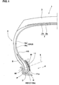
- Fig. 1 is a meridian sectional view showing a pneumatic tire having an accommodation tool of an electronic component of the present invention.
- Fig. 2 is an enlarged sectional view showing an accommodation tool and a bead portion of a first embodiment.
- Fig. 3 is a perspective view showing the accommodation tool.
- a pneumatic tire 1 (simply referred to as the "tire 1" in some cases) provided with an accommodation tool of an electronic component includes a tread portion 2 which comes into contact with a road surface, a pair of sidewall portions 3 extending from opposite ends of the tread portion 2 radially inward, and a bead portion 4 which is located radially inner end of each sidewall portions 3 and which is fitted over the rimR.
- the tire 1 is a radial tire for a passenger vehicle.
- the tire 1 is reinforced by a cord reinforcing layer, and necessary rigidity and strength are secured.
- the cord reinforcing layer includes at least a toroidal carcass 6 extending from a tread portion 2 to a bead core 5 of a bead portion 4 through a sidewall portion 3.
- the cord reinforcing layer includes the carcass 6 and a belt layer 7 existing radially outward of the carcass 6 and inside of the tread portion 2.
- the carcass 6 is formed of one or more (one, in this example) carcass ply 6A in which carcass cords are arranged at an angle of 70° to 90° with respect to the circumferential direction of the tire.
- the carcass ply 6A is continuously provided with a turnup portion 6b which is folded back and retained around the bead core 5 from inside to outside in the axial direction of the tire at opposite sides of a ply main body 6a extending between the bead cores 5 and 5.
- a bead apex rubber 8 is disposed between the ply main body 6a and the turnup portion 6b.
- the bead apex rubber 8 extends radially outward from the bead core 5 to reinforce the tire from the bead portion 4 to the sidewall portions 3, and has a triangular cross section.
- the belt layer 7 includes two or more (two, in this example) belt plies 7A and 7B in which belt cords are arranged at an angle of 10 to 35° with respect to the circumferential direction of the tire.
- the belt cords intersect with each other between the plies. With this, the belt rigidity is enhanced, and the tread portion 2 is strongly reinforced over its substantially entire width with hoop effect.
- a band layer (not shown) in which band cords are arranged at an angle of 5° with respect to the circumferential direction of the tire may be provided radially outward of the belt layer 7 to enhance the steering stability and durability at the time of high speed running.
- the tire 1 has a tire cavity surface HS made of known low air-permeable rubber such as butyl-based rubber for example. Withthis, thetirecavityisair-tightlyheld.
- Anaccommodation tool 11 provided therein with an accommodation space 10 for accommodating an electronic component W is mounted on the tire cavity surface HS.
- the electronic component W is sealed in the accommodation space 10 of the accommodation tool 11.
- the accommodation tool 11 includes a back sheet 13 on the side of the tire cavity surface HS, and a front sheet 14 superposed on the back sheet 13.
- the back sheet 13 and the front sheet 14 have peripheral edges 13E and 14E, respectively, and the entire peripheral edges 13E and 14E are bonded to each other, thereby forming the accommodation space 10 in which the electronic component W is sealed.
- the back sheet 13 and front sheet 14 are made of thin rubber sheets having thicknesses t1 and t2 of 2.0mm or less.
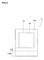
- the back sheet 13 and front sheet 14 have tetragonal shape having substantially the same widths and substantially the same lengths.
- one end of a back surface 11S of the accommodation tool 11 is provided with a bonding region 11Sb which is bonded to the tire cavity surface HS, and only the bonding region 11Sb is bonded to the tire cavity surface HS.
- a portion of the non-bonding region 11Sa on the other end side is free and can be separated from the tire cavity surface HS.
- the accommodation space 10 is formed in a portion of the non-bonding region 11Sa. Therefore, deformation, impact and heat of the tire during running can be restrained from being transmitted to the electronic component by freely separating the non-bonding region 11Sa from the tire cavity surface HS.
- the bonding region 11Sb is separated from the accommodation space 10 by at least 1.0 mm distance L2 (shown in Fig. 4).
- the bonding region 11Sb is bonded to a mounting portion HS1 in the tire cavity surface HS.
- the bead portion 4 is suitable as the mounting portion HS1. This is because that the bead portion 4 is a portion where deformation during running of the tire is the smallest and with this, the adverse influence such as impact applied to the electronic component W can be reduced. This is also preferable for suppressing peeling damage of the accommodation tool 11.
- the bead port ion 4 means a region radially inward of a reference line X which intersects with the play main body 6a of the carcass 6 from a separating point P at which the bead portion 4 is separated from a rim flange Rf.
- the "normal rim” is a rim determined for each tire by a standard including one on which the tire is based, and the normal rim is a standard rim in the case of JATMA, a "Design Rim” in the case of TRA, and a “Measuring Rim” in the case of ETRTO.
- "normal internal pressure” means an air pressure determined for each tire by a standard.
- the "normal internal pressure” is a maximum air pressure in JATMA, a maximum value described in "TIRE LOAD LIMITS AT VARIOUS COLD INFLATION PRESSURES" in the case of TRA, and "INFLATION PRESSURE” in the case of ETRTO.
- the normal internal pressure is 180 kPa.
- the portion of the non-bonding region 11sa may extend toward the sidewall portions 3 beyond the reference line X only if only the bonding region 11Sb is mounted on the bead portion 4. In this case also, the adverse influence on the electronic component W caused by impact or the like can be reduced to small level.
- one side 11a of the four sides forming a periphery of the accommodation tool 11 faces the tire rotation center line and the bonding region 11Sb is formed on the side of this side 11a.
- the bonding region 11Sb is formed on the side of this side 11a at which the accommodation tool 11 faces the tire rotation center line, i.e., on the side of the side 11a at which the accommodation tool 11 faces radially inward of the tire.
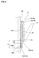
- the accommodation tool 11 may be formed into a bag-like shape in which one end 10a of the accommodation space 10 is provided with an opening 12 for accommodating an electronic component.
- a case in which the electronic component W is sealed by the accommodation tool 11 is called a first embodiment
- a case in which the accommodation tool 11 is formed into the bag-like shape having the opening 12 is called a second embodiment.
- the second embodiment is formed by bonding the peripheral edges 13E and 14E of the back sheet 13 and the front sheet 14 to each other, but there is an unbonded portion among the sides forming the periphery of the accommodation tool 11.
- the back sheet 13 and the front sheet 14 are formed into the tetragonal shapes having substantially the same widths, and three sides of the peripheral edge 13E and three sides of the peripheral edge 14E are bonded to each other except other one sides among four sides forming the periphery of the accommodation tool 11.
- the back sheet 13 is longer than the front sheet 14, and the opening 12 is formed at a location of an end edge 13a on the side of the one side of the back sheet 13 inward by a distance L1 of 3.0 mm or more.
- the accommodation tool 11 is formed such that the entire electronic component W is completely accommodated in the accommodation space 10 so that the electronic component W does not jump out from the opening 12 during running.
- the bonding region 11Sb is formed on the side of the side 11a where the accommodation tool 11 faces the tire rotation center line due to the same reason as that of the first embodiment.
- the opening 12 is opened toward the tire rotation center line.
- the bonding region 11Sb of the accommodation tool 11 and the tire cavity surface HS can be bonded to each other using existing various adhesives including the above-described adhesive.
- both of them are integrally bonded by vulcanization (vulcanization adhesive) at the time of vulcanization formation of the tire.
- the first embodiment includes at least
- the steps KA2 and KA3 are carried out first to previously form a raw accommodation tool 11N and then in step KA1, the raw back sheet 13N is disposed on the tire cavity surface HS in the state of the raw accommodation tool 11N.
- the back sheet 13N is formed into a tetragonal shape made of raw rubber sheet material having thickness t1 of 2.0 mm or less, and the back sheet 13N has the peripheral edge 13E which extends beyond the electronic component W.
- the electronic component W is placed on the back sheet 13N such that the peripheral edge 13E is left around the electronic component W.
- an electronic component W of tetragonal shape of 20 mm (width) ⁇ 30 mm (length) ⁇ 0.3 mm (thickness).
- step KA3 a raw front sheet 14N made of raw rubber sheet material having thickness t2 of 2.0 mm or less is disposed on the superposed body 21. At that time, the entire peripheral edge 14E of the front sheet 14N and the entire peripheral edge 13E of the back sheet 13N are superposed on and adhered to each other, and the raw accommodation tool 11N having the accommodation space 10 in which the electronic component W is sealed can easily be formed.
- step KA1 the back sheet 13N is disposed on and adhered to the tire cavity surface HS of the raw tire 1N and the bead portion 4 in the state of the raw accommodation tool 11N.
- a peeling sheet 23 which is a non-adhering layer is previously pasted on the back surface 11S and the non-bonding region 11Sa such that the non-bonding region 11sa is not vulcanized adhered to the tire cavity surface HS.
- the peeling sheet 23 is pasted such that all regions thereof except the bonding region 11Sb extend beyond the back surface 11S.
- a preferable peeling sheet 23 is a sheet obtained by subjecting a surface of a sheet body made of resin to a peeling processing, and resin material is not melted by heat of 180°C such as polyethylene terephtalate (PET), polyethylene naphthalate (PEN), polyetherimide (PEI), polyphenyether (PPS), polyimide (PI) and polyether ether ketone (PEEK).
- resin material is not melted by heat of 180°C
- PET polyethylene terephtalate
- PEN polyethylene naphthalate
- PEI polyetherimide
- PPS polyphenyether
- PI polyimide
- PEEK polyether ether ketone
- the peeling sheet 23 itself may be formed of only the mold release resin.
- the peeling sheet 23 is adhered to the back surface 11S of the accommodation tool 11 even after the vulcanization step.
- the mold release properties with respect to rubber on the side of the tire may be eliminated so that the peeling sheet 23 is released from the back surface 11S and adhered to the tire cavity surface HS after the vulcanization step.
- the steps may be carried out in the order of KA1 ⁇ KA2 (or KB2) ⁇ KA3 (OR KB3), i.e., the back sheet 13N may first be adhered to the tire cavity surface HS of the raw tire 1N and the electronic component W and the front sheet 14N may be sequentially provided on the back sheet 13N.
- the raw tire 1N is put into a vulcanization mold like the conventional tire and the tire is vulcanized and formed.
- the raw accommodation tool 11N is brought into contact with the raw tire 1N under pressure, and both of them can vulcanized and adhered and integrally bonded to each other.
- the thickness t1 and t2 of the back sheet 13N and the front sheet 14N are set 2.0 mm or less so that the pressure caused by the bladders is dispersed. If the thickness t1 and t2 are less than 0.4 mm, however, the thicknesses are too thin and it is difficult to secure strength for withstanding rotation of the tire. To secure the strength, it is possible to embed a body in which cords are arranged or a cloth reinforcing material such as canvas to reinforce the sheet.
- the back sheet 13N and the front sheet 14N it is possible to employ various rubbers which can be vulcanized and adhered to the inner liner rubber such as natural rubber (NR), polyisoprene rubber (IR), styrene butadiene rubber (SBR), butadiene rubber (BR) and butyl rubber (IIR) .
- natural rubber NR
- polyisoprene rubber IR
- SBR styrene butadiene rubber
- BR butadiene rubber
- IIR butyl rubber
- the invention is not limited to the illustrated embodiments, and the tires 1 can be formed as tires in various categories such as a dealer vehicle tire, a heavy load vehicle tire and a two-wheel vehicle tire in addition to a passenger vehicle tire.
- the accommodation space 10 can employ various shapes in accordance with the electronic component W in addition to the tetragonal shape.
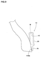
- the accommodation tool 11N may be formed into a non-sheet shape as shown in Fig. 9, instead of being sandwiched between the back sheet 13 and the front sheet 14.
- the accommodation tool 11 is integrally provided with a thick rubber massive main portion 25 in which the electronic component W is accommodated, and a tongue piece-like bonding portion 26 having the bonding region 11Sb which is to be bonded to the tire.
- the present invention can variously be modified and carried out, and for example, the accommodation space 10 may be used for accommodating various electronic components W such as a pressure sensor, a temperature sensor and an acceleration sensor other than the RFID transponder.
- a pneumatic tire (195/65R15) having the accommodation tool 11 of the structure shown in Figs. 2 and 3 was prototyped based the specification shown in Table 1.
- the electronic component is an electromagnetic induction type RFID tag (V720S) produced by Omron Co., Ltd., and communication frequency is 13.56 MHz.
- the prototyped tire in which the electronic component is inserted into the accommodation tool was allowed to run on a drum at speed (80 km/h) for 60 hours under conditions of rim (15 x 6 JJ), internal pressure (190 kPa) and vertical load (6.96 kN), and reception performance of the electronic component after running was confirmed by a reader (HS03 produced by Omron Co. , Ltd.).
- a data reading distance to the electronic component was 130 mm, a data writing distance was 130 mm, and it was confirmed that memory function was normally operated without loss of data.
Landscapes
- Engineering & Computer Science (AREA)
- Mechanical Engineering (AREA)
- Tires In General (AREA)
- Wire Bonding (AREA)
Abstract
Description
- The present invention relates to a pneumatic tire having an accommodation tool of an electronic component such as a Radio Frequency Identification (RFID) transponder for example.
- In recent years, in order to monitor various data such as an internal pressure, a temperature, and the number of revolutions of a tire, and in order to enhance safety and maintenance performance, a technique of mounting an electronic component such as an RFID transponder that records the various data has been proposed. The transponder is a small and light-weighted electronic component provided with a semiconductor, in which a transmit/receive circuit, a control circuit, a memory, and the like are formed into a chip, and an antenna. Commonly used transponders work without battery, capable of, when inquiry radio waves are received, transmitting various data in the memory as response radio waves using the received radio wave as electric power.
- One example of a method for mounting such an electronic component ona tire is, as disclosed in Japanese Laid-openUtility ModelApplicationsNo. H2-123404 and No. H2-123404, and the like, is such that the electronic component is embedded in a raw (non-vulcanized) tire to be integrally formed with the tire by vulcanizing adhesion during vulcanization formation. As another example, Japanese Laid-open Utility Model Application No. H2-123404 discloses a method in which the electronic component is adhered to a surface of the tire after the vulcanization.
- However, in any of the cases, since the electronic component and the tire are integrally fixed to each other, deformation and impact of the tire when a vehicle runs, and heat of the tire are strongly transmitted to the electronic component. Thus, there is a problem that the electronic component is damaged, and performance of the tire is deteriorated and trouble is generated. It is conceived that the electronic component is mounted on a bead portion which has a relatively small deformation amount, but this method is not sufficient, since deformation of certain level is generated.
- Based on an idea that an accommodation tool of an electronic component is bonded to a tire cavity surface only on the side of one end of the accommodation tool, it is an object of the present invention to provide a pneumatic tire capable of preventing deformation, impact and heat of the tire from being transmitted to the electronic component, and capable of effectivelypreventing deterioration of performance and trouble of the electronic component.
- To achieve the above object, the present invention provides a pneumatic tire having a tire cavity surface to which an accommodation tool for accommodating an electronic component is bonded, wherein
the accommodation tool includes an accommodation space for accommodating an electronic component therein, and includes a bonding region which is bonded to the tire cavity surface and which is provided on one end of a back surface directed to the tire cavity surface,
only the bonding region is bonded to the tire cavity surface, thereby making it possible to separate a portion of a non-bonding region on the side of the other end of the back surface from the tire cavity surface. - Since the present invention has the above-described structure, the other end of the accommodation tool can freely be separated from the tire cavity surface. Thus, it is possible to effectively prevent the deformation, impact and heat of the tire during running from being transmitted to the electronic component, and to effectively prevent the deterioration and trouble of the electronic component. Even if the electronic component is relatively large in size, the above merit can effectively be exhibited without adversely affecting the tire, and flexibility of selection of the electronic component can largely be enhanced.
-
- Fig. 1 is a sectional view showing an embodiment of a pneumatic tire of the present invention;
- Fig. 2 is an enlarged sectional view showing an accommodation tool and a bead portion of a first embodiment;
- Fig. 3 is a perspective view showing the accommodation tool;
- Fig. 4 is a rear view showing a back surface of a back sheet;
- Fig. 5 is an enlarged sectional view showing an accommodation tool and a bead portion of a second embodiment;
- Fig. 6 is a perspective view showing the accommodation tool;
- Fig. 7 (A) is a diagram showing a step of forming a superposed body in the accommodation tool of the first embodiment, and Fig. 7(B) is a diagram showing a step of loading a front sheet on the superposed body in the accommodation tool of the first embodiment;
- Fig. 8 is a diagram showing a step of disposing a back sheet on a raw tire; and
- Fig. 9 is a sectional view showing another example of the accommodation tool together with the bead portion.
- Embodiments of the present invention will be explained together with illustrated examples. Fig. 1 is a meridian sectional view showing a pneumatic tire having an accommodation tool of an electronic component of the present invention. Fig. 2 is an enlarged sectional view showing an accommodation tool and a bead portion of a first embodiment. Fig. 3 is a perspective view showing the accommodation tool.
- As shown in Fig. 1, a pneumatic tire 1 (simply referred to as the "tire 1" in some cases) provided with an accommodation tool of an electronic component includes a
tread portion 2 which comes into contact with a road surface, a pair ofsidewall portions 3 extending from opposite ends of thetread portion 2 radially inward, and abead portion 4 which is located radially inner end of eachsidewall portions 3 and which is fitted over the rimR. In this example, the tire 1 is a radial tire for a passenger vehicle. - The tire 1 is reinforced by a cord reinforcing layer, and necessary rigidity and strength are secured. The cord reinforcing layer includes at least a
toroidal carcass 6 extending from atread portion 2 to abead core 5 of abead portion 4 through asidewall portion 3. In this example, the cord reinforcing layer includes thecarcass 6 and abelt layer 7 existing radially outward of thecarcass 6 and inside of thetread portion 2. - The
carcass 6 is formed of one or more (one, in this example)carcass ply 6A in which carcass cords are arranged at an angle of 70° to 90° with respect to the circumferential direction of the tire. Thecarcass ply 6A is continuously provided with aturnup portion 6b which is folded back and retained around thebead core 5 from inside to outside in the axial direction of the tire at opposite sides of a plymain body 6a extending between thebead cores bead apex rubber 8 is disposed between the plymain body 6a and theturnup portion 6b. Thebead apex rubber 8 extends radially outward from thebead core 5 to reinforce the tire from thebead portion 4 to thesidewall portions 3, and has a triangular cross section. - The
belt layer 7 includes two or more (two, in this example)belt plies tread portion 2 is strongly reinforced over its substantially entire width with hoop effect. A band layer (not shown) in which band cords are arranged at an angle of 5° with respect to the circumferential direction of the tire may be provided radially outward of thebelt layer 7 to enhance the steering stability and durability at the time of high speed running. - The tire 1 has a tire cavity surface HS made of known low air-permeable rubber such as butyl-based rubber for example. Withthis, thetirecavityisair-tightlyheld.
Anaccommodation tool 11 provided therein with anaccommodation space 10 for accommodating an electronic component W is mounted on the tire cavity surface HS. - In this example, as shown in Figs. 2 and 3, the electronic component W is sealed in the
accommodation space 10 of theaccommodation tool 11. More specifically, theaccommodation tool 11 includes aback sheet 13 on the side of the tire cavity surface HS, and afront sheet 14 superposed on theback sheet 13. Theback sheet 13 and thefront sheet 14 haveperipheral edges peripheral edges accommodation space 10 in which the electronic component W is sealed. Theback sheet 13 andfront sheet 14 are made of thin rubber sheets having thicknesses t1 and t2 of 2.0mm or less. In this example, theback sheet 13 andfront sheet 14 have tetragonal shape having substantially the same widths and substantially the same lengths. - In this invention, one end of a
back surface 11S of theaccommodation tool 11 is provided with a bonding region 11Sb which is bonded to the tire cavity surface HS, and only the bonding region 11Sb is bonded to the tire cavity surface HS. With this structure, a portion of the non-bonding region 11Sa on the other end side is free and can be separated from the tire cavity surface HS. Theaccommodation space 10 is formed in a portion of the non-bonding region 11Sa. Therefore, deformation, impact and heat of the tire during running can be restrained from being transmitted to the electronic component by freely separating the non-bonding region 11Sa from the tire cavity surface HS. As a result, the electronic component W is prevented from being damaged and it is possible to prevent the deterioration of performance and trouble of the electronic component W. Thus, it is preferable that the bonding region 11Sb is separated from theaccommodation space 10 by at least 1.0 mm distance L2 (shown in Fig. 4). - The bonding region 11Sb is bonded to a mounting portion HS1 in the tire cavity surface HS. The
bead portion 4 is suitable as the mounting portion HS1. This is because that thebead portion 4 is a portion where deformation during running of the tire is the smallest and with this, the adverse influence such as impact applied to the electronic component W can be reduced. This is also preferable for suppressing peeling damage of theaccommodation tool 11. - As shown in Fig . 1, the
bead port ion 4 means a region radially inward of a reference line X which intersects with the playmain body 6a of thecarcass 6 from a separating point P at which thebead portion 4 is separated from a rim flange Rf. The "normal rim" is a rim determined for each tire by a standard including one on which the tire is based, and the normal rim is a standard rim in the case of JATMA, a "Design Rim" in the case of TRA, and a "Measuring Rim" in the case of ETRTO. Further, "normal internal pressure" means an air pressure determined for each tire by a standard. The "normal internal pressure" is a maximum air pressure in JATMA, a maximum value described in "TIRE LOAD LIMITS AT VARIOUS COLD INFLATION PRESSURES" in the case of TRA, and "INFLATION PRESSURE" in the case of ETRTO. When the tire is for a passenger vehicle, the normal internal pressure is 180 kPa. - In the
accommodation tool 11, the portion of the non-bonding region 11sa may extend toward thesidewall portions 3 beyond the reference line X only if only the bonding region 11Sb is mounted on thebead portion 4. In this case also, the adverse influence on the electronic component W caused by impact or the like can be reduced to small level. In this example, oneside 11a of the four sides forming a periphery of theaccommodation tool 11 faces the tire rotation center line and the bonding region 11Sb is formed on the side of thisside 11a. In other words, the bonding region 11Sb is formed on the side of thisside 11a at which theaccommodation tool 11 faces the tire rotation center line, i.e., on the side of theside 11a at which theaccommodation tool 11 faces radially inward of the tire. In this case, a large electronic component W exceeding the reference line X can be mounted, and flexibility of selection of the electronic component W is largely enhanced. Further, in this case, since the centrifugal force during rotation of the tire is applied in a direction pulling theaccommodation tool 11 radially outward, bending fatigue at the boundary position between the bonding region 11sb and the non-bonding region 11Sa can be reduced, and the durability of theaccommodation tool 11 can be enhanced. - As shown in Figs. 5 and 6, the
accommodation tool 11 may be formed into a bag-like shape in which oneend 10a of theaccommodation space 10 is provided with anopening 12 for accommodating an electronic component. For the sake of convenience, a case in which the electronic component W is sealed by theaccommodation tool 11 is called a first embodiment, and a case in which theaccommodation tool 11 is formed into the bag-like shape having theopening 12 is called a second embodiment. - The second embodiment is formed by bonding the
peripheral edges back sheet 13 and thefront sheet 14 to each other, but there is an unbonded portion among the sides forming the periphery of theaccommodation tool 11.
Particularly in this example, theback sheet 13 and thefront sheet 14 are formed into the tetragonal shapes having substantially the same widths, and three sides of theperipheral edge 13E and three sides of theperipheral edge 14E are bonded to each other except other one sides among four sides forming the periphery of theaccommodation tool 11. At that time, it is preferable that theback sheet 13 is longer than thefront sheet 14, and theopening 12 is formed at a location of anend edge 13a on the side of the one side of theback sheet 13 inward by a distance L1 of 3.0 mm or more. With this structure, the electronic component W can be brought into and out from theaccommodation space 10 easily, and the electronic component W can be exchanged in the event of trouble of the electronic component W. Theaccommodation tool 11 is formed such that the entire electronic component W is completely accommodated in theaccommodation space 10 so that the electronic component W does not jump out from theopening 12 during running. - In the second embodiment also, it is preferable that the bonding region 11Sb is formed on the side of the
side 11a where theaccommodation tool 11 faces the tire rotation center line due to the same reason as that of the first embodiment. At that time, it is further preferable that theopening 12 is opened toward the tire rotation center line. With this structure, it is possible to further prevent the electronic component W from jumping out from theopening 12 due to the centrifugal force during running. In order to further prevent the electronic component W from jumping out from theopening 12, it is preferable that theopening 12 closed using adhesive such as acrylic adhesive, rubber adhesive and silicone adhesive. - In the present invention, the bonding region 11Sb of the
accommodation tool 11 and the tire cavity surface HS can be bonded to each other using existing various adhesives including the above-described adhesive. However, in order to secure higher bonding strength, it is preferable that both of them are integrally bonded by vulcanization (vulcanization adhesive) at the time of vulcanization formation of the tire. - Next, a producing method of the pneumatic tire 1 according to the first embodiment in which the bonding region 11Sb and the tire cavity surface HS are bonded by vulcanization will be explained. More specifically, the first embodiment includes at least
- (1) a step KA1 of disposing a
raw back sheet 13N on the tire cavity surface HS of theraw tire 1N and the bead portion 4 (Fig. 8); - (2) a step KA2 of disposing the electronic component W on the
raw back sheet 13N to form a superposed body 21 (Fig. 7(A)); and - (3) a step KA3 of disposing a
raw back sheet 14N on the superposedbody 21 to cover the electronic component W (Fig. 7 (B)) . - In this embodiment, the steps KA2 and KA3 are carried out first to previously form a
raw accommodation tool 11N and then in step KA1, theraw back sheet 13N is disposed on the tire cavity surface HS in the state of theraw accommodation tool 11N. - The
back sheet 13N is formed into a tetragonal shape made of raw rubber sheet material having thickness t1 of 2.0 mm or less, and theback sheet 13N has theperipheral edge 13E which extends beyond the electronic component W. In step KA2, the electronic component W is placed on theback sheet 13N such that theperipheral edge 13E is left around the electronic component W. In this example, there is used an electronic component W of tetragonal shape of 20 mm (width) × 30 mm (length) × 0.3 mm (thickness). - In step KA3, a
raw front sheet 14N made of raw rubber sheet material having thickness t2 of 2.0 mm or less is disposed on the superposedbody 21. At that time, the entireperipheral edge 14E of thefront sheet 14N and the entireperipheral edge 13E of theback sheet 13N are superposed on and adhered to each other, and theraw accommodation tool 11N having theaccommodation space 10 in which the electronic component W is sealed can easily be formed. - Next, in step KA1, as shown in Fig. 8, the
back sheet 13N is disposed on and adhered to the tire cavity surface HS of theraw tire 1N and thebead portion 4 in the state of theraw accommodation tool 11N. At that time, a peelingsheet 23 which is a non-adhering layer is previously pasted on theback surface 11S and the non-bonding region 11Sa such that the non-bonding region 11sa is not vulcanized adhered to the tire cavity surface HS. The peelingsheet 23 is pasted such that all regions thereof except the bonding region 11Sb extend beyond theback surface 11S. Apreferable peeling sheet 23 is a sheet obtained by subjecting a surface of a sheet body made of resin to a peeling processing, and resin material is not melted by heat of 180°C such as polyethylene terephtalate (PET), polyethylene naphthalate (PEN), polyetherimide (PEI), polyphenyether (PPS), polyimide (PI) and polyether ether ketone (PEEK). As the peeling processing, it is possible to employ processing for coating the sheet body with mold release resin such as poly fluor ethylene-based resin and silicone-based resin having mold release properties with respect to rubber. Alternatively, it is possible to employ processing for applying liquid mold release agent including silicone oil or the like to the surface. Alternatively, the peelingsheet 23 itself may be formed of only the mold release resin. In this example, the peelingsheet 23 is adhered to theback surface 11S of theaccommodation tool 11 even after the vulcanization step. However, the mold release properties with respect to rubber on the side of the tire may be eliminated so that the peelingsheet 23 is released from theback surface 11S and adhered to the tire cavity surface HS after the vulcanization step. - In the producing method, the steps may be carried out in the order of KA1 → KA2 (or KB2) → KA3 (OR KB3), i.e., the
back sheet 13N may first be adhered to the tire cavity surface HS of theraw tire 1N and the electronic component W and thefront sheet 14N may be sequentially provided on theback sheet 13N. - Then, the
raw tire 1N is put into a vulcanization mold like the conventional tire and the tire is vulcanized and formed. At that time, since bladders are expanded, theraw accommodation tool 11N is brought into contact with theraw tire 1N under pressure, and both of them can vulcanized and adhered and integrally bonded to each other. - If the
raw accommodation tool 11N is too thick, the pressure caused by the bladders is concentrated, and the tire 1 and theaccommodation tool 11 are deformed. Therefore, it is preferable that the thickness t1 and t2 of theback sheet 13N and thefront sheet 14N are set 2.0 mm or less so that the pressure caused by the bladders is dispersed. If the thickness t1 and t2 are less than 0.4 mm, however, the thicknesses are too thin and it is difficult to secure strength for withstanding rotation of the tire. To secure the strength, it is possible to embed a body in which cords are arranged or a cloth reinforcing material such as canvas to reinforce the sheet. As theback sheet 13N and thefront sheet 14N, it is possible to employ various rubbers which can be vulcanized and adhered to the inner liner rubber such as natural rubber (NR), polyisoprene rubber (IR), styrene butadiene rubber (SBR), butadiene rubber (BR) and butyl rubber (IIR) . - Although the especially preferred embodiments have been described in detail above, the invention is not limited to the illustrated embodiments, and the tires 1 can be formed as tires in various categories such as a dealer vehicle tire, a heavy load vehicle tire and a two-wheel vehicle tire in addition to a passenger vehicle tire. The
accommodation space 10 can employ various shapes in accordance with the electronic component W in addition to the tetragonal shape. Theaccommodation tool 11N may be formed into a non-sheet shape as shown in Fig. 9, instead of being sandwiched between theback sheet 13 and thefront sheet 14. In this case, theaccommodation tool 11 is integrally provided with a thick rubber massivemain portion 25 in which the electronic component W is accommodated, and a tongue piece-like bonding portion 26 having the bonding region 11Sb which is to be bonded to the tire. The present invention can variously be modified and carried out, and for example, theaccommodation space 10 may be used for accommodating various electronic components W such as a pressure sensor, a temperature sensor and an acceleration sensor other than the RFID transponder. - In accordance with the producing method of the first embodiment, a pneumatic tire (195/65R15) having the
accommodation tool 11 of the structure shown in Figs. 2 and 3 was prototyped based the specification shown in Table 1. A reception confirming test in a running state in an electronic component W (RFID transponder) accommodated in theaccommodation tool 11 was carried out. The electronic component is an electromagnetic induction type RFID tag (V720S) produced by Omron Co., Ltd., and communication frequency is 13.56 MHz. - The prototyped tire in which the electronic component is inserted into the accommodation tool was allowed to run on a drum at speed (80 km/h) for 60 hours under conditions of rim (15 x 6 JJ), internal pressure (190 kPa) and vertical load (6.96 kN), and reception performance of the electronic component after running was confirmed by a reader (HS03 produced by Omron Co. , Ltd.). A data reading distance to the electronic component was 130 mm, a data writing distance was 130 mm, and it was confirmed that memory function was normally operated without loss of data.
[Table 1] Raw back sheet Material SBR Size 52mm (width) × 42mm (length) × 0.7mm (thickness) Size of electronic component 20mm (width) × 30mm (length) × 0.3mm (thickness) Raw front sheet Material SBR Size 50mm (width) × 40mm (length) × 0.7mm (thickness) Peeling sheet Size 42mm (width) × 45mm (length) × 0.075mm (thickness) Mode release processing Coating with Teflon (trademark of DuPont) Mounting portion Bead portion Bonding region On a side facing the rotation center line 12mm (width) × 42mm (length) Accommodation space Electronic component is sealed.
Claims (9)
- A pneumatic tire having a tire cavity surface to which an accommodation tool for accommodating an electronic component is bonded, wherein
the accommodation tool includes an accommodation space for accommodating an electronic component therein, and includes a bonding region which is bonded to the tire cavity surface and which is provided on one end of a back surface directed to the tire cavity surface,
only the bonding region is bonded to the tire cavity surface, thereby making it possible to separate a portion of a non-bonding region on the side of the other end of the back surface from the tire cavity surface. - The pneumatic tire having the accommodation tool for accommodating the electronic component according to claim 1, wherein the accommodation space is formed in a portion of the non-bonding region.
- The pneumatic tire having the accommodation tool for accommodating the electronic component according to claim 1 or 2 , wherein the bonding region of the accommodation tool is bonded to a bead portion.
- The pneumatic tire having the accommodation tool for accommodating the electronic component according to any one of claims 1 to 3, wherein the bonding region is formed on the side of a side facing a tire rotation center line.
- The pneumatic tire having the accommodation tool for accommodating the electronic component according to any one of claims 1 to 4, wherein the electronic component is sealed in the accommodation space of the accommodation tool.
- The pneumatic tire having the accommodation tool for accommodating the electronic component according to any one of claims 1 to 4, wherein the accommodation tool is formed into a bag-like shape having an opening through which the electronic component is brought into and out from the accommodation space.
- The pneumatic tire having the accommodation tool for accommodating the electronic component according to claim 6, wherein the opening is opened such as to face the tire rotation center line.
- The pneumatic tire having the accommodation tool for accommodating the electronic component according to any one of claims 1 to 7, wherein the accommodation tool comprises a rubber back sheet directed to the tire cavity surface, and a rubber front sheet superposed on the back sheet, a peripheral edge of the back sheet and a peripheral edge of the front sheet are bonded to each other, thereby forming the accommodation space.
- The pneumatic tire having the accommodation tool for accommodating the electronic component according to any one of claims 1 to 8, wherein the back surface of the accommodation tool or the tire cavity surface is provided with a non-adhering layer for forming the non-bonding region.
Applications Claiming Priority (1)
| Application Number | Priority Date | Filing Date | Title |
|---|---|---|---|
| JP2004361735A JP4599150B2 (en) | 2004-12-14 | 2004-12-14 | Pneumatic tire with electronic parts storage |
Publications (3)
| Publication Number | Publication Date |
|---|---|
| EP1671817A2 true EP1671817A2 (en) | 2006-06-21 |
| EP1671817A3 EP1671817A3 (en) | 2010-04-14 |
| EP1671817B1 EP1671817B1 (en) | 2011-06-15 |
Family
ID=35884030
Family Applications (1)
| Application Number | Title | Priority Date | Filing Date |
|---|---|---|---|
| EP05026846A Expired - Lifetime EP1671817B1 (en) | 2004-12-14 | 2005-12-08 | Pneumatic tire having accommodation tool of electronic component |
Country Status (4)
| Country | Link |
|---|---|
| US (1) | US7430906B2 (en) |
| EP (1) | EP1671817B1 (en) |
| JP (1) | JP4599150B2 (en) |
| CN (1) | CN100471706C (en) |
Cited By (3)
| Publication number | Priority date | Publication date | Assignee | Title |
|---|---|---|---|---|
| JP2007320553A (en) * | 2006-05-30 | 2007-12-13 | Goodyear Tire & Rubber Co:The | Transponder carrier for tire |
| EP2692551A1 (en) * | 2012-07-30 | 2014-02-05 | The Goodyear Tire & Rubber Company | Bonding to a pneumatic tire |
| US9381781B2 (en) | 2012-07-30 | 2016-07-05 | The Goodyear Tire & Rubber Company | Bonding to a pneumatic tire |
Families Citing this family (20)
| Publication number | Priority date | Publication date | Assignee | Title |
|---|---|---|---|---|
| JP4878939B2 (en) * | 2006-07-05 | 2012-02-15 | 株式会社ブリヂストン | Pneumatic tire manufacturing method |
| JP4705560B2 (en) * | 2006-12-05 | 2011-06-22 | 住友ゴム工業株式会社 | IC tag, pneumatic tire to which it is attached, and method for attaching IC tag |
| JP2009298328A (en) * | 2008-06-13 | 2009-12-24 | Bridgestone Corp | Pneumatic tire |
| US8430142B2 (en) * | 2009-02-25 | 2013-04-30 | The Goodyear Tire & Rubber Company | Environmentally resistant assembly containing an electronic device for use in a tire |
| US20120091209A1 (en) * | 2009-06-29 | 2012-04-19 | Elizabeth Hotaling | Flexible middle layer for rfid patch on tires |
| US9016118B2 (en) | 2010-12-22 | 2015-04-28 | Caterpillar Inc. | Mounting structure |
| US8596117B2 (en) | 2011-10-03 | 2013-12-03 | Bridgestone Americas Tire Operations, Llc | Attachment patch for mounting various devices |
| FR2981010B1 (en) * | 2011-10-05 | 2014-06-13 | Michelin Soc Tech | KIT AND METHOD FOR TEMPORARILY FIXING AN ELECTRONIC DEVICE ON A SUPPORT OF A PNEUMATIC ENVELOPE |
| US20130133800A1 (en) * | 2011-11-29 | 2013-05-30 | Jean-Claude Patrice Philippe Griffoin | System for attaching an electronic device or other item to a pneumatic tire |
| KR101435409B1 (en) * | 2012-12-05 | 2014-08-29 | 정보통신산업진흥원 | RFID tag for tire |
| US20140261944A1 (en) * | 2013-03-15 | 2014-09-18 | The Goodyear Tire & Rubber Company | Encasing for releasably containing a device and tire containing such encasing or encased device |
| WO2016099633A1 (en) | 2014-12-19 | 2016-06-23 | Bridgestone Americas Tire Operations, Llc | Attachment patch for mounting devices |
| JP6917232B2 (en) * | 2017-07-24 | 2021-08-11 | 株式会社ブリヂストン | Pneumatic tires |
| DE102018213664A1 (en) * | 2018-08-14 | 2020-02-20 | Continental Reifen Deutschland Gmbh | Technical rubber article comprising at least one transmitting and / or receiving device and use of an adhesive composition for fastening at least one transmitting and / or receiving device on a surface of a technical rubber article |
| JP7192433B2 (en) * | 2018-11-21 | 2022-12-20 | 横浜ゴム株式会社 | pneumatic tire |
| JP6686109B1 (en) * | 2018-11-26 | 2020-04-22 | Toyo Tire株式会社 | tire |
| JP7404629B2 (en) * | 2019-03-20 | 2023-12-26 | 住友ゴム工業株式会社 | tire |
| JP7671136B2 (en) * | 2020-11-20 | 2025-05-01 | Toyo Tire株式会社 | tire |
| JP7603422B2 (en) * | 2020-11-20 | 2024-12-20 | Toyo Tire株式会社 | tire |
| CN117882084A (en) * | 2021-08-30 | 2024-04-12 | 普利司通美国轮胎运营有限责任公司 | RFID package for tire |
Citations (3)
| Publication number | Priority date | Publication date | Assignee | Title |
|---|---|---|---|---|
| JPH02123404A (en) | 1988-11-02 | 1990-05-10 | Komatsu Ltd | Guiding system for unmanned traveling vehicle |
| EP0689950A2 (en) | 1994-06-03 | 1996-01-03 | BRIDGESTONE/FIRESTONE, Inc. | Method of monitoring conditions of vehicle tires and tires containing a monitoring device therein |
| DE10243441A1 (en) | 2002-09-18 | 2004-04-01 | Continental Aktiengesellschaft | Tire transponder |
Family Cites Families (16)
| Publication number | Priority date | Publication date | Assignee | Title |
|---|---|---|---|---|
| US5181975A (en) * | 1991-03-27 | 1993-01-26 | The Goodyear Tire & Rubber Company | Integrated circuit transponder with coil antenna in a pneumatic tire for use in tire identification |
| US7549327B2 (en) * | 2001-02-16 | 2009-06-23 | Automotive Technologies International, Inc. | Tire-mounted energy generator and monitor |
| US6868717B2 (en) * | 1998-10-16 | 2005-03-22 | Bridgestone/Firestone North America Tire, Llc | Method and device to encapsulate tire tag |
| GB9916914D0 (en) | 1999-07-20 | 1999-09-22 | Sumitomo Rubber Ind | Method of attaching an article to the inside of a tyre cavity |
| DE19940086A1 (en) * | 1999-08-24 | 2001-03-15 | Georg Siegel Gmbh Zur Verwertu | Identification of tyre using transponder adhered to inside and retrieving information using reader |
| DE60043263D1 (en) * | 1999-11-24 | 2009-12-17 | Michelin Rech Tech | MONITORED VEHICLE TIRES AND HOLDERS FOR MONITORING DEVICE |
| JP4411501B2 (en) | 2000-10-30 | 2010-02-10 | 横浜ゴム株式会社 | Pneumatic tire provided with a transponder and manufacturing method thereof |
| JP2003165313A (en) * | 2001-11-28 | 2003-06-10 | Pacific Ind Co Ltd | Tire condition monitoring device |
| EP1344658A1 (en) * | 2002-03-12 | 2003-09-17 | Siemens Aktiengesellschaft | Device for obtaining the tyre pressure of a vehicle tyre |
| JP4183032B2 (en) * | 2002-08-30 | 2008-11-19 | 横浜ゴム株式会社 | Pneumatic tire equipped with a film-like electronic device and method for attaching the film-like electronic device |
| DE10255138A1 (en) * | 2002-11-26 | 2004-06-17 | Iq-Mobil Electronics Gmbh | Holding device for fastening an electronic component |
| US7091841B2 (en) * | 2003-02-19 | 2006-08-15 | Michelin Recherche Et Technique, S.A. | Tire electronics assembly having a multi-frequency antenna |
| JP4248893B2 (en) * | 2003-02-24 | 2009-04-02 | 横浜ゴム株式会社 | Mounting structure for tire electronic components |
| JP4066929B2 (en) * | 2003-10-08 | 2008-03-26 | 株式会社日立製作所 | Electronic device and manufacturing method thereof |
| KR100555659B1 (en) * | 2003-12-22 | 2006-03-03 | 삼성전자주식회사 | Self-generated sensing module and tire pressure monitoring system using it |
| US7338914B2 (en) * | 2004-03-31 | 2008-03-04 | Intermec Ip Corp. | RFID tire label |
-
2004
- 2004-12-14 JP JP2004361735A patent/JP4599150B2/en not_active Expired - Fee Related
-
2005
- 2005-12-08 EP EP05026846A patent/EP1671817B1/en not_active Expired - Lifetime
- 2005-12-13 CN CNB2005101346262A patent/CN100471706C/en not_active Expired - Fee Related
- 2005-12-13 US US11/299,892 patent/US7430906B2/en not_active Expired - Fee Related
Patent Citations (3)
| Publication number | Priority date | Publication date | Assignee | Title |
|---|---|---|---|---|
| JPH02123404A (en) | 1988-11-02 | 1990-05-10 | Komatsu Ltd | Guiding system for unmanned traveling vehicle |
| EP0689950A2 (en) | 1994-06-03 | 1996-01-03 | BRIDGESTONE/FIRESTONE, Inc. | Method of monitoring conditions of vehicle tires and tires containing a monitoring device therein |
| DE10243441A1 (en) | 2002-09-18 | 2004-04-01 | Continental Aktiengesellschaft | Tire transponder |
Cited By (5)
| Publication number | Priority date | Publication date | Assignee | Title |
|---|---|---|---|---|
| JP2007320553A (en) * | 2006-05-30 | 2007-12-13 | Goodyear Tire & Rubber Co:The | Transponder carrier for tire |
| EP1870262A2 (en) | 2006-05-30 | 2007-12-26 | The Goodyear Tire & Rubber Company | Transponder carrier for a tire |
| EP1870262A3 (en) * | 2006-05-30 | 2011-05-04 | The Goodyear Tire & Rubber Company | Transponder carrier for a tire |
| EP2692551A1 (en) * | 2012-07-30 | 2014-02-05 | The Goodyear Tire & Rubber Company | Bonding to a pneumatic tire |
| US9381781B2 (en) | 2012-07-30 | 2016-07-05 | The Goodyear Tire & Rubber Company | Bonding to a pneumatic tire |
Also Published As
| Publication number | Publication date |
|---|---|
| EP1671817A3 (en) | 2010-04-14 |
| EP1671817B1 (en) | 2011-06-15 |
| US20060123899A1 (en) | 2006-06-15 |
| JP4599150B2 (en) | 2010-12-15 |
| CN100471706C (en) | 2009-03-25 |
| US7430906B2 (en) | 2008-10-07 |
| CN1789027A (en) | 2006-06-21 |
| JP2006168472A (en) | 2006-06-29 |
Similar Documents
| Publication | Publication Date | Title |
|---|---|---|
| EP1671817B1 (en) | Pneumatic tire having accommodation tool of electronic component | |
| EP3756909B1 (en) | Tire integrated with electronic device and manufacturing method thereof | |
| EP3632666B1 (en) | Tire manufacturing method | |
| CN110978905A (en) | tire | |
| JP2020055456A (en) | Tire and manufacturing method of tire | |
| CN111216494A (en) | Tyre for vehicle wheels | |
| JP7674654B2 (en) | Manufacturing method of pneumatic tire | |
| US20260109181A1 (en) | Pneumatic tire equipped with a transponder | |
| JP7019839B2 (en) | Pneumatic tire with transponder | |
| JP4555673B2 (en) | PNEUMATIC TIRE WITH ELECTRONIC COMPONENT STORAGE AND METHOD | |
| CN110709263A (en) | vehicle tires | |
| JP2020055459A (en) | tire | |
| US12227038B2 (en) | Pneumatic tyre equipped with a transponder | |
| JP4204845B2 (en) | Pneumatic tire provided with electronic chip and manufacturing method thereof | |
| EP4328050B1 (en) | Tire | |
| EP4422854B1 (en) | Method of producing a tyre equipped with an electronic device | |
| CN115066342A (en) | Pneumatic tire | |
| EP4212364B1 (en) | Heavy duty pneumatic tire | |
| EP4364976B1 (en) | TIRES | |
| US12570061B2 (en) | Production method for retreaded tire and retreaded tire | |
| US12441140B2 (en) | Solid tire and method for manufacturing same | |
| JP7703407B2 (en) | Pneumatic tires | |
| WO2025099663A1 (en) | Method of producing a tyre equipped with an electronic device | |
| JP2025120721A (en) | tire | |
| JP2020055520A (en) | Tire and manufacturing method of tire |
Legal Events
| Date | Code | Title | Description |
|---|---|---|---|
| PUAI | Public reference made under article 153(3) epc to a published international application that has entered the european phase |
Free format text: ORIGINAL CODE: 0009012 |
|
| AK | Designated contracting states |
Kind code of ref document: A2 Designated state(s): AT BE BG CH CY CZ DE DK EE ES FI FR GB GR HU IE IS IT LI LT LU LV MC NL PL PT RO SE SI SK TR |
|
| AX | Request for extension of the european patent |
Extension state: AL BA HR MK YU |
|
| PUAL | Search report despatched |
Free format text: ORIGINAL CODE: 0009013 |
|
| AK | Designated contracting states |
Kind code of ref document: A3 Designated state(s): AT BE BG CH CY CZ DE DK EE ES FI FR GB GR HU IE IS IT LI LT LU LV MC NL PL PT RO SE SI SK TR |
|
| AX | Request for extension of the european patent |
Extension state: AL BA HR MK YU |
|
| 17P | Request for examination filed |
Effective date: 20100722 |
|
| 17Q | First examination report despatched |
Effective date: 20100818 |
|
| AKX | Designation fees paid |
Designated state(s): DE FR GB |
|
| RIC1 | Information provided on ipc code assigned before grant |
Ipc: B60C 23/04 20060101AFI20101125BHEP |
|
| GRAP | Despatch of communication of intention to grant a patent |
Free format text: ORIGINAL CODE: EPIDOSNIGR1 |
|
| GRAS | Grant fee paid |
Free format text: ORIGINAL CODE: EPIDOSNIGR3 |
|
| GRAA | (expected) grant |
Free format text: ORIGINAL CODE: 0009210 |
|
| AK | Designated contracting states |
Kind code of ref document: B1 Designated state(s): DE FR GB |
|
| REG | Reference to a national code |
Ref country code: GB Ref legal event code: FG4D |
|
| REG | Reference to a national code |
Ref country code: DE Ref legal event code: R096 Ref document number: 602005028492 Country of ref document: DE Effective date: 20110728 |
|
| PLBE | No opposition filed within time limit |
Free format text: ORIGINAL CODE: 0009261 |
|
| STAA | Information on the status of an ep patent application or granted ep patent |
Free format text: STATUS: NO OPPOSITION FILED WITHIN TIME LIMIT |
|
| 26N | No opposition filed |
Effective date: 20120316 |
|
| REG | Reference to a national code |
Ref country code: DE Ref legal event code: R097 Ref document number: 602005028492 Country of ref document: DE Effective date: 20120316 |
|
| PGFP | Annual fee paid to national office [announced via postgrant information from national office to epo] |
Ref country code: GB Payment date: 20131219 Year of fee payment: 9 |
|
| PGFP | Annual fee paid to national office [announced via postgrant information from national office to epo] |
Ref country code: DE Payment date: 20140227 Year of fee payment: 9 |
|
| PGFP | Annual fee paid to national office [announced via postgrant information from national office to epo] |
Ref country code: FR Payment date: 20131220 Year of fee payment: 9 |
|
| REG | Reference to a national code |
Ref country code: DE Ref legal event code: R119 Ref document number: 602005028492 Country of ref document: DE |
|
| GBPC | Gb: european patent ceased through non-payment of renewal fee |
Effective date: 20141208 |
|
| REG | Reference to a national code |
Ref country code: FR Ref legal event code: ST Effective date: 20150831 |
|
| PG25 | Lapsed in a contracting state [announced via postgrant information from national office to epo] |
Ref country code: GB Free format text: LAPSE BECAUSE OF NON-PAYMENT OF DUE FEES Effective date: 20141208 Ref country code: DE Free format text: LAPSE BECAUSE OF NON-PAYMENT OF DUE FEES Effective date: 20150701 |
|
| PG25 | Lapsed in a contracting state [announced via postgrant information from national office to epo] |
Ref country code: FR Free format text: LAPSE BECAUSE OF NON-PAYMENT OF DUE FEES Effective date: 20141231 |