EP1344658A1 - Device for obtaining the tyre pressure of a vehicle tyre - Google Patents
Device for obtaining the tyre pressure of a vehicle tyre Download PDFInfo
- Publication number
- EP1344658A1 EP1344658A1 EP02005633A EP02005633A EP1344658A1 EP 1344658 A1 EP1344658 A1 EP 1344658A1 EP 02005633 A EP02005633 A EP 02005633A EP 02005633 A EP02005633 A EP 02005633A EP 1344658 A1 EP1344658 A1 EP 1344658A1
- Authority
- EP
- European Patent Office
- Prior art keywords
- tire
- carrier
- antenna
- electronics unit
- approximately
- Prior art date
- Legal status (The legal status is an assumption and is not a legal conclusion. Google has not performed a legal analysis and makes no representation as to the accuracy of the status listed.)
- Withdrawn
Links
Images

Classifications
-
- H—ELECTRICITY
- H01—ELECTRIC ELEMENTS
- H01Q—ANTENNAS, i.e. RADIO AERIALS
- H01Q1/00—Details of, or arrangements associated with, antennas
- H01Q1/12—Supports; Mounting means
- H01Q1/22—Supports; Mounting means by structural association with other equipment or articles
- H01Q1/2208—Supports; Mounting means by structural association with other equipment or articles associated with components used in interrogation type services, i.e. in systems for information exchange between an interrogator/reader and a tag/transponder, e.g. in Radio Frequency Identification [RFID] systems
- H01Q1/2241—Supports; Mounting means by structural association with other equipment or articles associated with components used in interrogation type services, i.e. in systems for information exchange between an interrogator/reader and a tag/transponder, e.g. in Radio Frequency Identification [RFID] systems used in or for vehicle tyres
-
- B—PERFORMING OPERATIONS; TRANSPORTING
- B60—VEHICLES IN GENERAL
- B60C—VEHICLE TYRES; TYRE INFLATION; TYRE CHANGING; CONNECTING VALVES TO INFLATABLE ELASTIC BODIES IN GENERAL; DEVICES OR ARRANGEMENTS RELATED TO TYRES
- B60C23/00—Devices for measuring, signalling, controlling, or distributing tyre pressure or temperature, specially adapted for mounting on vehicles; Arrangement of tyre inflating devices on vehicles, e.g. of pumps or of tanks; Tyre cooling arrangements
- B60C23/02—Signalling devices actuated by tyre pressure
- B60C23/04—Signalling devices actuated by tyre pressure mounted on the wheel or tyre
- B60C23/0491—Constructional details of means for attaching the control device
- B60C23/0493—Constructional details of means for attaching the control device for attachment on the tyre
Definitions
- the invention relates to a device for detecting the tire pressure a motor vehicle tire.
- the tire pressure must be from Motor vehicle tires are checked regularly.
- devices for measuring the tire pressure in each tire have at least one pressure sensor which measures the tire pressure.
- the measured value is then in one Signal with the help of a transmitter via an antenna to one transmitted vehicle-side receiver.
- the transfer can take place intermittently at predetermined time intervals or upon receipt of a prompt signal from a vehicle transmitter is broadcast. Together with the Prompt signal can transmit energy to the device which is then used to return the pressure signal to send to the vehicle.
- an individual can also Identification of the tire are included in the pressure signal.
- the identifier is in the electronics unit of each Tire saved. That of the on-board receivers received pressure signals are a central vehicle-side Evaluation unit supplied, in which then each signal evaluated and the measured pressure with approved reference values is compared. In the event of a deviation from the reference value a display is activated that shows the driver that he takes appropriate measures (changing tires or refilling air) should initiate. For security, several can Measurements made and from it an average or a time-dependent Value can be determined, which then with the reference value, which can also change over time become.
- a known device (EP 0 657 836 B1) has an electronics unit arranged on a tire of the vehicle is.
- a coil is connected to the electronics unit, the circumference of the tire and completely on the inner tire wall or attached to the inner tread of the tire is. With this electronics unit, the pressure in the tire measured.
- the on-board antenna receives a prompt signal transmits, as a result of the reception of the request signal the pressure signal via the antenna wirelessly to the Received antenna on-board.
- the vehicle If the vehicle is moving (i.e. the wheels are turning), deform it tire on the one hand due to the load of the vehicle (Walking in the Latsch area) and on the other hand due to the prevailing centrifugal force. Since in the known device the antenna is attached directly to the inside of the tire wall the antenna is subject to a large mechanical Stress, especially with additional, larger vibrations of the tire, if, for example, over a curb or a threshold is driven. Because the well-known antenna is firmly connected to the elastic tire. It exists hence the risk of the antenna breaking because it is in the Contrary to the rubber tire is not so elastic.
- the device shows an electronics unit with an antenna connected is. Both the electronics unit and the antenna are on an approximately elastic, ring-shaped Carrier arranged along its inner circumference is attached to the tire, while the outer peripheral side is free protrudes into the interior of the tire.
- the antenna is around Rim around and arranged approximately coaxially to the wheel axis.
- Fastening the carrier to the tire can be done in the manufacturing process of the tire can be integrated.
- the carrier and therefore the electronics unit are then permanently assigned to the tire.
- Such a carrier can also be retrofitted or for every tire interchangeable if a tire change or a repair of the Tire takes place.
- the antenna can be used as a coil with a or several turns can be arranged on the circumference of the carrier and be largely surrounded by the carrier material. Thereby the antenna itself is protected from environmental influences. If the carrier is made of a flexible material, so vibrations are dampened by mechanical action transferred to the wearer on the tire. At the Turning the wheels does not result in crushing the ring. Even when the tire is subjected to extreme loads (such as cornering) or extreme crushing of the tire (moving the tire over a sharp edge) and the resulting contact of the tire with the carrier, this can be due to its flexibility or elasticity the mechanical load largely field so that the antenna and electronics unit are largely protected.
- the carrier is preferably with its antenna on the inner, the wall of the tire facing the vehicle in the area attached to the tire bead. So the antenna is as possible close to an antenna arranged on the vehicle, the usually arranged in the vicinity of the wheel or the shock absorber is. Minor signals are then sufficient to transmit signals Energys from. For devices with their own energy supply (Battery) this saves energy and lasts longer. For battery-free devices (Transponder method) requires less energy to the device back to be transmitted, then the pressure signal can be sent back.
- the carrier can be manufactured by injection molding, whereby the antenna and the electronics unit during injection molding be injected with and thus of carrier material are surrounded and protected by them. So that the tire pressure measured exactly by a pressure sensor of the electronics unit can be, the carrier material in the area of Electronics unit has a hole that an air duct between represents the air in the tire and the pressure sensor.
- the carrier can also be a flexible, electrically insulating Fabric can be made by appropriate Cut and fold the fabric of the antenna and the Encloses electronics unit. It is also important to ensure that that an air duct to the electronics unit is provided, so that the pressure in the tire is genuine and accurately measured can be.
- the carrier preferably has an approximately rectangular profile cross section. Depending on the number of turns of the coil antenna and the size of the electronics unit and its housing the carrier can also be T-shaped or approximately L-shaped in its shape Profile cross section be formed.
- the carrier when driving and thus when turning the wheels is not too mechanically loaded, it points in the area an approximately annular reinforcing element of the tire bead on. Through this reinforcing element during rotation the wheel of the carrier mechanically stabilized and mechanically relieved by reducing the tensile force on the carrier.
- a device for detecting the tire pressure of a motor vehicle tire has an electronics unit 1 on ( Figure 1), the at least one not shown Pressure sensor and possibly a temperature sensor. It can other sensors, such as an acceleration sensor, Centrifugal force sensor, speed sensor or contain a motion sensor in the electronics unit 1 his. These can serve, for example, that from one predetermined, measured value of a corresponding physical Size of the transmission of the pressure signal is triggered or that an initialization (tire identifier is the evaluation unit communicated) or a localization (recognized Wheel position is assigned to the identifier).
- the tire pressure is measured with the pressure sensor.
- the Temperature sensor measures the temperature in the tire. In order to the measured pressure value can be corrected if necessary.
- the electronics unit 1 has a not shown Transmitter, with the help of which the measured pressure value is transmitted as a pressure signal via an antenna 2.
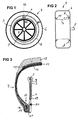
- FIG. 1 shows a section through Wheel 4, which has a tire 6 mounted on a rim 5.
- the carrier 3 is on a side wall 7 of the tire 6 attached near the rim 5.
- the antenna 2 is formed as a coil with one or more turns, wherein the windings approximately coaxial to the wheel axis 8 around the rim 5 run around.
- the antenna 2 is electrical via connecting lines 9 (see FIG. 3) with the electronics unit 1 connected.
- FIG. 2 shows a front view of the wheel 4, the rim 5 and the carrier 3 shown in dashed lines because they are located inside the tire 6. Out This figure clearly shows that the carrier 3 on the inner, the vehicle side facing side wall 7 of Tire 6 is attached. The one on the same page Wheel axis 8 represents the vehicle side.
- the carrier 3 is in the region of the circumference directed towards the rim 5 glued to the tire bead 10.
- the carrier 3 stands at this Embodiment on a foot surface 11 of the tire 6 (a so-called tire toe or toeguard). So there there are also no sealing problems for the tubeless tire 6, since the carrier 3 does not touch the rim 5.
- the tire 6 is an example tubeless radial tire with a conventional. tire structure with a tread 12, one or more belt layers 13 made of steel cord and / or nylon cord, a carcass 14 and an airtight rubber layer 15 for sealing the tire 6.
- the device can of course also with all others Types of tubeless tires 6 are used at which the carrier 3 according to the invention on the tire 6 in the disclosed manner can be attached.
- the carrier 3 is at the lower end of the sidewall 7 of the tire 6 in the area of the bead 10 as far as possible on his attached outer peripheral edge.
- the bead 10 consists of a Bead core 16 with a steel cord 17 for mechanical stabilization of the bead 10.
- the free end (outer support circumference) of the carrier 3 protrudes into the interior of the tire.
- the carrier 3 is such fixed in the tire 6 that the outer carrier circumference all around has a minimum safety distance from the tire 6, so that the carrier 3 only under unfavorable conditions rarely strikes the tire 6 and so due to its elasticity not mechanically impaired or damaged can. Conversely, the carrier 3 can the inner wall of the tire do not damage due to its elasticity.
- the antenna 2 is a coil with one or arranged several turns.
- the antenna 2 is via connecting lines 9 connected to the electronics unit 1.
- the Electronics unit 1 is near the bead 10 and thus arranged as close as possible to the wheel axle 8 so that the Electronics unit 1 generated additional unbalance when turning of the wheel 4 is as low as possible.
- the carrier 3 has one in the area of the electronics unit 1 Air duct 19 through which an open connection between the pressure sensor of the electronics unit 1 and the air in the tire 6 exists.
- the tire pressure can thus be safe and genuine be measured.
- the profile cross section of the carrier 3 (as shown in Figure 3 is) is approximately T-shaped here.
- the T shape is by the five turns of the antenna shown here 2 conditional. With only one turn, the carrier 3 is on its outer peripheral edge thinner and the profile cross section is then approximately rectangular.
- the profile cross section can also be approximately L-shaped. It is advantageous if the Profile cross-section uniform and over the entire circumference is constant, so that no additional one due to this symmetry Imbalance arises and thus the carrier 3 and the mechanical Connection to the tire 6 (adhesive or vulcanizing surface) less is mechanically loaded.
- the carrier 3 is made of a flexible, elastic material, such as rubber or polyurethane (PUR).
- the elastic material can also be reinforced by fabric material become.
- the carrier 3 can be molded by injection molding be, antenna 2 and electronics unit 1 at Injection molding. Antenna 2 and electronics unit 1 are thus complete (with the exception of the air duct 19) surrounded by carrier material.
- the carrier material may do not be rigid, but must be flexible or compliant be designed so that vibrations are damped by the material and not too much the attachment of the carrier 3 mechanically load the tire 6.
- the carrier 3 must be somewhat can be arranged vibration-stable in the tire 6 and remain in its position even with larger shocks. So it should have some stiffness achieved, for example, by the reinforcing fabric introduced becomes.
- the carrier 3 also from an electrically insulating Material is made, so the turns of the antenna 2 are overmolded as bare wires and are therefore of the other electrically conductive parts.
- the electronics unit 1 then does not need to be housed in a separate housing become. As a result, the electronics unit 1 and also the antenna 2 lighter and make a smaller unbalance represents.
- Another flexible material can also be used as the carrier material be, for example, by a special fabric (e.g. glass fiber) or by another suitable substance is reinforced. This material can then be cut out and folding (the antenna 2 and the electronics unit 1 are hammered in) form the shape of the carrier 3. Antenna 2 and electronics unit 1 are thus from surrounded the material. Only the air duct 19 becomes free left so that a connection between the pressure sensor of the Electronics unit 1 and the tire air is present to the Measure pressure safely.
- a special fabric e.g. glass fiber
- This material can then be cut out and folding (the antenna 2 and the electronics unit 1 are hammered in) form the shape of the carrier 3. Antenna 2 and electronics unit 1 are thus from surrounded the material. Only the air duct 19 becomes free left so that a connection between the pressure sensor of the Electronics unit 1 and the tire air is present to the Measure pressure safely.
- the circumferential, annular reinforcement element 20 can, for example be a steel ring.
- fiber reinforced Fabrics from the nylon family such as aramid (e.g. with the trade names Kevlar®, Twaron® or Nomex®) become.
- Aramid reinforcing fibers have a very high energy absorption (impact resistance), a very high specific strength and very high tensile strength and Vibration damping. The chemical resistance and water resistance is also good.
- the carrier 3 is protruding freely into the tire interior End in the radial direction towards the tread 12 and in lateral direction to the side wall 7 towards with a distance the tire 6 mounted. This will also make it unfavorable mechanical conditions a contact of tire 6 and carrier 3 avoided, which provides protection for the carrier 3.
- the carrier 3 can on the side wall 7 lean on the tire 6, but both damage the tire 6 and the carrier 3 is due to the elasticity of the wearer largely excluded.
- the carrier 3 must be elastic, flexible and resilient to mechanical loads when turning the wheels 4 at least cushioning to catch.
- the carrier 3 with his Components (antenna 2, electronics unit 1, reinforcing element 20) have a low weight.
- the carrier 3 can be glued or vulcanized to the tire bead 10 are attached. Particularly high stability reached when the carrier 3 along the entire inner circumference is fixed in the region of the tire bead 10. Other, Functionally equivalent fastening types are also possible.
- Typical dimensions for the carrier 3, for example one 15 inch tires are about 48 cm for the outer diameter, for the inside diameter about 38 cm and for its thickness about 3 mm. This results in a width of approximately circular Carrier 3 of about 5 cm.
- the electronics unit 1 should be of a weight Minimum be reduced.
- the weight of the electronics unit is currently 1 about 3 to 5 g.
- the carrier 3 is designed approximately like an oversized washer, which, however, is flexible and therefore also collapsible is. This will make warehousing easier.
- the carrier 3 with antenna 2 and electronics unit 1 can also be used as a spare part can be retrofitted in each tire 6.
- identification data can include the date of manufacture, manufacturer parameters, Tire type, maximum speed, maximum axle load and / or a more favorable tire pressure range can be used.
- VR front right
- VL front left
- HR rear right
- HL rear left
- Each carrier 3 is on the inside of the vehicle attached side wall 7 of the respective hoop attached. If now corresponding - not shown - receiving antennas are arranged on the vehicle side near the wheels 4 (for example on the strut 21 or near the wheel axle 8), so the signals can be well and safely from the devices in the wheels on the receivers on the vehicle side and from there are transmitted to a central evaluation unit. There the antennas approximately coaxially around the wheel axis 8 or rim 5 are arranged, the transmission path remains between tire-side antenna 2 and vehicle-side antenna always of equal length. There will be reproducible transmission ratios manufactured.
- the devices are preferably at carrier frequencies operated by about 125 kHz, increasing the range of the signals is already very limited with only a low transmission power (Range usually less than 50 cm).
- these frequencies are special antennas 2 in the form of coils suitable, resulting in an inductive transmission of the signals leads. Therefore, it goes without saying that the antenna 2 used both as a transmitting and receiving antenna can be.
- the antenna 2 can be a closed antenna ring (360 ° antenna), it can also have one or more turns, the last one in the area of the connecting lines Turn is not completely closed. Signals can go from and to the antenna 2 are transmitted using the transformer principle (i.e. with an additional coupling coil). When complete closed turns can also be called a current clamp be used to supply signals to the antenna 2 or which to tap from there.
- Such an antenna 2 also lasts for longer operating times (i.e. over years in which the tire 6 is mounted) the mechanical loads occurring during operation are good because they are protected by the carrier 3 in the tire 6 is.
- the carrier 3 is therefore of its mechanics designed to last at least as long as it does for them Tire life is provided.
Abstract
Description
Die Erfindung betrifft eine Vorrichtung zum Erfassen des Reifendrucks eines Kraftfahrzeugreifens.The invention relates to a device for detecting the tire pressure a motor vehicle tire.
Aus sicherheitstechnischen Gründen muss der Reifendruck von Kraftfahrzeugreifen regelmäßig überprüft werden. Hierzu sind in jedem Reifen Vorrichtungen zum Erfassen des Reifendrucks angeordnet. Diese weisen zumindest einen Drucksensor auf, der den Reifendruck misst. Der gemessene Wert wird dann in einem Signal mit Hilfe eines Senders über eine Antenne zu einem fahrzeugseitigen Empfänger übertragen. Die Übertragung kann dabei intermittierend in vorgegebenen Zeitabständen erfolgen oder nach Empfang eines Aufforderungssignals, das von einem fahrzeugseitigen Sender ausgesendet wird. Zusammen mit dem Aufforderungssignal kann Energie zu der Vorrichtung übertragen werden, die dann dazu benutzt wird, das Drucksignal zurück zum Fahrzeug zu senden.For safety reasons, the tire pressure must be from Motor vehicle tires are checked regularly. For this are devices for measuring the tire pressure in each tire arranged. These have at least one pressure sensor which measures the tire pressure. The measured value is then in one Signal with the help of a transmitter via an antenna to one transmitted vehicle-side receiver. The transfer can take place intermittently at predetermined time intervals or upon receipt of a prompt signal from a vehicle transmitter is broadcast. Together with the Prompt signal can transmit energy to the device which is then used to return the pressure signal to send to the vehicle.
Zusammen mit den Drucksignalen kann auch eine individuelle Kennung des Reifens in dem Drucksignal mitgesendet werden. Die Kennung ist jeweils in der Elektronikeinheit eines jeden Reifens gespeichert. Die von den fahrzeugseitigen Empfängern empfangenen Drucksignale werden einer fahrzeugseitigen, zentralen Auswerteeinheit zugeführt, in der dann jedes Signal ausgewertet und der gemessene Druck mit zugelassenen Referenzwerten verglichen wird. Bei Abweichung von dem Referenzwert wird eine Anzeige aktiviert, die dem Fahrer anzeigt, dass er geeignete Maßnahmen (Reifenwechsel oder Luft nachfüllen) einleiten sollte. Zur Sicherheit können auch mehrere Messungen gemacht und daraus ein Mittelwert oder ein zeitabhängiger Wert ermittelt werden, die dann mit dem Referenzwert, der sich ebenfalls zeitlich ändern kann, verglichen werden.Together with the pressure signals, an individual can also Identification of the tire are included in the pressure signal. The identifier is in the electronics unit of each Tire saved. That of the on-board receivers received pressure signals are a central vehicle-side Evaluation unit supplied, in which then each signal evaluated and the measured pressure with approved reference values is compared. In the event of a deviation from the reference value a display is activated that shows the driver that he takes appropriate measures (changing tires or refilling air) should initiate. For security, several can Measurements made and from it an average or a time-dependent Value can be determined, which then with the reference value, which can also change over time become.
Eine bekannte Vorrichtung (EP 0 657 836 B1) weist eine Elektronikeinheit auf, die an einem Reifen des Fahrzeugs angeordnet ist. Mit der Elektronikeinheit ist eine Spule verbunden, die am Umfang des Reifens und vollständig an der inneren Reifenwand oder an der inneren Lauffläche des Reifens befestigt ist. Mit dieser Elektronikeinheit wird der Druck im Reifen gemessen. Wenn die fahrzeugseitige Antenne ein Aufforderungssignal aussendet, so wird infolge des Empfangs des Aufforderungssignals das Drucksignal über die Antenne drahtlos zu der fahrzeugseitigen Empfangsantenne zurückgesendet.A known device (EP 0 657 836 B1) has an electronics unit arranged on a tire of the vehicle is. A coil is connected to the electronics unit, the circumference of the tire and completely on the inner tire wall or attached to the inner tread of the tire is. With this electronics unit, the pressure in the tire measured. When the on-board antenna receives a prompt signal transmits, as a result of the reception of the request signal the pressure signal via the antenna wirelessly to the Received antenna on-board.
Wenn das Fahrzeug fährt (d.h. die Räder drehen sich), so verformen sich die Reifen einerseits aufgrund der Last des Fahrzeugs (Walken im Latschbereich) und andererseits aufgrund der herrschenden Zentrifugalkraft. Da bei der bekannten Vorrichtung die Antenne unmittelbar innen an der Reifenwand befestigt ist, unterliegt die Antenne einer großen mechanischen Belastung, insbesondere bei zusätzlichen, größeren Erschütterungen des Reifens, wenn beispielsweise über ein Bordstein oder eine Bodenschwelle gefahren wird. Denn die bekannte Antenne ist fest mit dem elastischen Reifen verbunden. Es besteht daher die Gefahr, dass die Antenne bricht, da sie im Gegensatz zu dem Gummireifen nicht so elastisch ist.If the vehicle is moving (i.e. the wheels are turning), deform it tire on the one hand due to the load of the vehicle (Walking in the Latsch area) and on the other hand due to the prevailing centrifugal force. Since in the known device the antenna is attached directly to the inside of the tire wall the antenna is subject to a large mechanical Stress, especially with additional, larger vibrations of the tire, if, for example, over a curb or a threshold is driven. Because the well-known antenna is firmly connected to the elastic tire. It exists hence the risk of the antenna breaking because it is in the Contrary to the rubber tire is not so elastic.
Es ist ein Ziel der Erfindung, eine Vorrichtung zum Erfassen des Reifendrucks eines Kraftfahrzeugreifens zu schaffen, deren Elektronikbauteile auch über längere Betriebsstandzeiten zuverlässig funktionieren.It is an object of the invention to provide a detection device to create the tire pressure of a motor vehicle tire, the Electronic components even over longer service lives work reliably.
Dieses Ziel wird erfindungsgemäß durch eine Vorrichtung zum
Erfassen des Reifendrucks eines Kraftfahrzeugreifens mit den
Merkmalen von Patentanspruch 1 gelöst. Dabei weist die Vorrichtung
eine Elektronikeinheit auf, die mit einer Antenne
verbunden ist. Sowohl die Elektronikeinheit als auch die Antenne
sind dabei auf einem etwa elastischen, ringscheibenförmigen
Träger angeordnet, der entlang seines inneren Umfangs
am Reifen befestigt ist, während die äußere Umfangsseite frei
in den Innenraum des Reifens ragt.This aim is achieved according to the invention by a device for
Detecting the tire pressure of a motor vehicle tire with the
Features of
Durch diese einseitige Einspannung am Reifen und dem elastischen, flexiblen Träger werden Schwingungen und mechanische Belastungen, die auf den Reifen einwirken, nur gedämpft auf den Träger und dessen Elektronikeinheit sowie Antenne übertragen. Diese Elektronikbauteile werden daher im Betrieb des Kraftfahrzeugs nur wenig mechanisch belastet.This one-sided clamping on the tire and the elastic, flexible carriers become vibrations and mechanical Loads that act on the tires are only dampened transmit the carrier and its electronics unit and antenna. These electronic components are therefore in the operation of the Motor vehicle only little mechanical stress.
Bei der erfindungsgemäßen Vorrichtung ist die Antenne um die Felge herum und etwa koaxial zur Radachse angeordnet. Durch diese achssymmetrische Anordnung zusätzliche Unwuchten weitgehend vermieden. Da die Antenne über den Umfang des Reifens angeordnet ist, können Daten zwischen der Antenne und einer fahrzeugseitig angeordneten Antenne gut hin- und her übertragen werden, falls die fahrzeugseitige Antenne in der Nähe des Rades angeordnet ist.In the device according to the invention, the antenna is around Rim around and arranged approximately coaxially to the wheel axis. By this axisymmetric arrangement largely additional unbalance avoided. Because the antenna over the circumference of the tire is arranged, data between the antenna and a transmit the antenna on the vehicle side well back and forth if the vehicle antenna near the Wheel is arranged.
Durch diesen Träger ist die gesamte Masse des Trägers plus Elektronikeinheit und Antenne etwa gleichmäßig über den Umfang verteilt, so dass nur geringe, durch den Träger bedingte Unwuchten auf das Rad und somit die Fahrstabilität wirken.Through this carrier is the entire mass of the carrier plus electronics unit and antenna about evenly over the circumference distributed so that only slight imbalances caused by the carrier affect the bike and thus the driving stability.
Das Befestigen des Trägers am Reifen kann in das Fertigungsverfahren des Reifens integriert werden. Der Träger und damit die Elektronikeinheit sind dann dem Reifen fest zugeordnet. Ein solcher Träger ist auch für jeden Reifen nachrüstbar oder austauschbar, wenn ein Reifenwechsel oder eine Reparatur des Reifens stattfindet.Fastening the carrier to the tire can be done in the manufacturing process of the tire can be integrated. The carrier and therefore the electronics unit are then permanently assigned to the tire. Such a carrier can also be retrofitted or for every tire interchangeable if a tire change or a repair of the Tire takes place.
Vorteilhafte Ausgestaltungen der Erfindung ergeben sich aus den Unteransprüchen. So kann die Antenne als Spule mit einer oder mehreren Windungen am Umfang des Trägers angeordnet sein und weitgehend von dem Trägermaterial umgeben sein. Dadurch ist die Antenne selber geschützt vor Umwelteinflüssen. Wenn der Träger aus einem flexiblen Material hergestellt ist, so werden Schwingungen gedämpft, die durch mechanische Einwirkung auf den Reifen zum Träger hin übertragen werden. Beim Drehen der Räder ergeben sich keine Quetschungen des Rings. Selbst bei extremer Belastung des Reifens (wie Kurvenfahrt) oder extremen Quetschungen des Reifens (Bewegen des Reifens über eine scharfe Kante) und daraus resultierender Berührung des Reifens mit dem Träger, kann dieser durch seine Flexibilität oder Elastizität die mechanische Belastung weitgehend auffangen, so dass die Antenne und die Elektronikeinheit weitgehend geschützt sind.Advantageous refinements of the invention result from the subclaims. So the antenna can be used as a coil with a or several turns can be arranged on the circumference of the carrier and be largely surrounded by the carrier material. Thereby the antenna itself is protected from environmental influences. If the carrier is made of a flexible material, so vibrations are dampened by mechanical action transferred to the wearer on the tire. At the Turning the wheels does not result in crushing the ring. Even when the tire is subjected to extreme loads (such as cornering) or extreme crushing of the tire (moving the tire over a sharp edge) and the resulting contact of the tire with the carrier, this can be due to its flexibility or elasticity the mechanical load largely field so that the antenna and electronics unit are largely protected.
Der Träger ist mit seiner Antenne vorzugsweise an der inneren, der Fahrzeugseite zugewandten Wand des Reifens im Bereich des Reifenwulstes befestigt. Somit ist die Antenne möglichst nahe an einer fahrzeugseitig angeordneten Antenne, die üblicherweise in der Nähe des Rades oder des Federbeines angeordnet ist. Zum Übertragen von Signalen reichen dann geringe Energien aus. Bei Vorrichtungen mit eigener Energieversorgung (Batterie) wird dadurch die Energieversorgung geschont und hält länger an. Bei batterielosen Vorrichtungen (Transponderverfahren) braucht weniger Energie zu der Vorrichtung hin übertragen zu werden, damit dann das Drucksignal zurückgesendet werden kann.The carrier is preferably with its antenna on the inner, the wall of the tire facing the vehicle in the area attached to the tire bead. So the antenna is as possible close to an antenna arranged on the vehicle, the usually arranged in the vicinity of the wheel or the shock absorber is. Minor signals are then sufficient to transmit signals Energies from. For devices with their own energy supply (Battery) this saves energy and lasts longer. For battery-free devices (Transponder method) requires less energy to the device back to be transmitted, then the pressure signal can be sent back.
Da die beiden Antennen nahe beieinander angeordnet sind, können die Daten mit niederfrequente Trägerfrequenzen moduliert übertragen werden. Diese Signale haben ohnehin eine kurze Reichweite. Dies hat jedoch den Vorteil, dass die Drucksignale von Vorrichtungen in den anderen Reifen des Fahrzeugs nicht empfangen werden. Es ist somit eine eindeutige Zuordnung möglich von jeder Vorrichtung in jeweils einem Reifen zu der jeweiligen Radposition.Since the two antennas are arranged close together, modulates the data with low-frequency carrier frequencies be transmitted. These signals have a short one anyway Range. However, this has the advantage that the pressure signals of devices in the other tires of the vehicle not be received. It is therefore a clear assignment possible from each device in one tire at a time the respective wheel position.
Der Träger kann mittels Spritzgießen hergestellt werden, wobei die Antenne und die Elektronikeinheit während des Spritzgießens mit eingespritzt werden und somit von Trägermaterial umgeben sowie durch diese geschützt sind. Damit der Reifendruck durch einen Drucksensor der Elektronikeinheit exakt gemessen werden kann, weist das Trägermaterial im Bereich der Elektronikeinheit ein Loch auf, das einen Luftkanal zwischen der Luft im Reifen und dem Drucksensor darstellt.The carrier can be manufactured by injection molding, whereby the antenna and the electronics unit during injection molding be injected with and thus of carrier material are surrounded and protected by them. So that the tire pressure measured exactly by a pressure sensor of the electronics unit can be, the carrier material in the area of Electronics unit has a hole that an air duct between represents the air in the tire and the pressure sensor.
Der Träger kann auch durch einen flexiblen, elektrisch isolierenden Stoff hergestellt werden, der durch entsprechendes Zurechtschneiden und Falten des Stoffes die Antenne und die Elektronikeinheit umschließt. Auch hierbei ist darauf zu achten, dass ein Luftkanal zur Elektronikeinheit vorgesehen ist, damit der Druck im Reifen unverfälscht und genau gemessen werden kann.The carrier can also be a flexible, electrically insulating Fabric can be made by appropriate Cut and fold the fabric of the antenna and the Encloses electronics unit. It is also important to ensure that that an air duct to the electronics unit is provided, so that the pressure in the tire is genuine and accurately measured can be.
Der Träger hat vorzugsweise eine etwa rechteckförmigen Profilquerschnitt. Je nach Anzahl der Windungen der Spulenantenne und der Größe der Elektronikeinheit und dessen Gehäuse kann der Träger auch T-förmig oder etwa L-förmig in seinem Profilquerschnitt ausgebildet sein.The carrier preferably has an approximately rectangular profile cross section. Depending on the number of turns of the coil antenna and the size of the electronics unit and its housing the carrier can also be T-shaped or approximately L-shaped in its shape Profile cross section be formed.
Damit der Träger beim Fahren und damit beim Drehen der Räder nicht zu sehr mechanisch belastet wird, weist er im Bereich des Reifenwulstes ein etwa ringförmiges Verstärkungselement auf. Durch dieses Verstärkungselement wird bei der Drehung des Rades der Träger mechanisch stabilisiert und mechanisch durch Vermindern der Zugkraft auf den Träger entlastet.So that the carrier when driving and thus when turning the wheels is not too mechanically loaded, it points in the area an approximately annular reinforcing element of the tire bead on. Through this reinforcing element during rotation the wheel of the carrier mechanically stabilized and mechanically relieved by reducing the tensile force on the carrier.
Ein Ausführungsbeispiel der Erfindung wird im Folgenden anhand der schematischen Zeichnungen näher erläutert. Es zeigen:
Figur 1- eine Seitenansicht eines Reifens mit einer erfindungsgemäßen Vorrichtung zum Erfassen des Reifendrucks eines Kraftfahrzeugreifens,
Figur 2- eine Vorderansicht des Reifens nach
Figur 1, Figur 3- einen Schnitt durch den Reifen entlang der Linie III-III in Figur 1 (in Vergrößerung) und
Figur 4- eine schematische Ansicht der vier Räder eines Kraftfahrzeugs,
in die jeweils eine erfindungsgemäße Vorrichtung
gemäß
Figur 1 eingebaut ist.
- Figure 1
- 1 shows a side view of a tire with a device according to the invention for detecting the tire pressure of a motor vehicle tire,
- Figure 2
- 2 shows a front view of the tire according to FIG. 1,
- Figure 3
- a section through the tire along the line III-III in Figure 1 (in enlargement) and
- Figure 4
- is a schematic view of the four wheels of a motor vehicle, in each of which a device according to the invention according to Figure 1 is installed.
Eine erfindungsgemäße Vorrichtung zum Erfassen des Reifendrucks
eines Kraftfahrzeugreifens weist eine Elektronikeinheit
1 auf (Figur 1), die zumindest einen nicht dargestellten
Drucksensor und ggf. einen Temperatursensor aufwetst. Es können
auch noch andere Sensoren, wie beispielsweise ein Beschleunigungssensor,
Fliehkraftsensor, Drehzahlsensor oder
ein Bewegungssensor in der Elektronikeinheit 1 enthalten
sein. Diese können beispielsweise dazu dienen, dass ab einem
vorbestimmten, gemessenen Wert einer entsprechenden physikalischen
Größe das Aussenden des Drucksignals ausgelöst wird
oder dass eine Initialisierung (Reifenkennung wird der Auswerteeinheit
mitgeteilt) oder eine Lokalisierung (erkannte
Radposition wird der Kennung zugeordnet) ausgelöst werden.A device according to the invention for detecting the tire pressure
of a motor vehicle tire has an
Mit dem Drucksensor wird der Reifendruck gemessen. Mit dem
Temperatursensor wird die Temperatur im Reifen gemessen. Damit
kann der gemessene Druckwert ggf. korrigiert werden. Des
Weiteren weist die Elektronikeinheit 1 einen nicht dargestellten
Sender auf, mit dessen Hilfe der gemessene Druckwert
als Drucksignal über eine Antenne 2 ausgesendet wird.The tire pressure is measured with the pressure sensor. With the
Temperature sensor measures the temperature in the tire. In order to
the measured pressure value can be corrected if necessary. Of
Furthermore, the
Bei der erfindungsgemäßen Vorrichtung zum Erfassen des Reifendrucks
eines Kraftfahrzeugreifens ist die Elektronikeinheit
1 und die Antenne 2 auf einem etwa ringscheibenförmigen
Träger 3 angeordnet. Figur 1 zeigt einen Schnitt durch ein
Rad 4, das einen auf eine Felge 5 montierten Reifen 6 aufweist.
Der Träger 3 ist dabei an einer Seitenwand 7 des Reifens
6 in der Nähe der Felge 5 befestigt. Die Antenne 2 ist
als Spule mit einer oder mehreren Windungen ausgebildet, wobei
die Windungen etwa koaxial zur Radachse 8 um die Felge 5
herum verlaufen. Die Antenne 2 ist elektrisch über Verbindungsleitungen
9 (vgl. Figur 3) mit der Elektronikeinheit 1
verbunden.In the device for detecting the tire pressure according to the invention
the electronic unit of a
In Figur 2 ist eine Vorderansicht des Rades 4 dargestellt,
wobei die Felge 5 und der Träger 3 gestrichelt dargestellt
sind, da diese sich innerhalb des Reifens 6 befinden. Aus
dieser Figur ist gut ersichtlich, dass der Träger 3 an der
inneren, der Fahrzeugseite hin zugewandten Seitenwand 7 des
Reifens 6 befestigt ist. Die auf derselben Seite befindliche
Radachse 8 stellt dabei die Fahrzeugseite dar.FIG. 2 shows a front view of the
Im vergrößerten Schnitt durch den Reifen 6, wie er in Figur 3
dargestellt ist, ist die Befestigung des Trägers 3 am Reifen
6 im Bereich des Reifenwulstes 10 gut zu erkennen. Der Träger
3 ist im Bereich des zu der Felge 5 hin gerichteten Umfangs
an den Reifenwulst 10 angeklebt. Der Träger 3 steht bei diesem
Ausführungsbeispiel auf einer Fußfläche 11 des Reifens 6
(einer so genannten Reifenzehe oder Toeguard) auf. Somit gibt
es auch keine Dichtungsprobleme für den schlauchlosen Reifen
6, da der Träger 3 die Felge 5 nicht berührt.In an enlarged section through the tire 6, as shown in FIG. 3
is shown, the attachment of the
Bei dem Reifen 6 handelt es sich beispielhaft um einen
schlauchlosen Radialreifen mit einem herkömmlichen. Reifenaufbau
mit einer Lauffläche 12, ein oder mehreren Gürtellagen 13
aus Stahlcord und/oder aus Nyloncord, einer Karkasse 14 und
einer luftdichten Gummischicht 15 zum Abdichten des Reifens
6. Die Vorrichtung kann selbstverständlich auch bei allen anderen
Typen von schlauchlosen Reifen 6 verwendet werden, bei
denen der erfindungsgemäße Träger 3 an dem Reifen 6 in der
offenbarten Weise befestigt werden kann.The tire 6 is an example
tubeless radial tire with a conventional. tire structure
with a
Der Träger 3 ist am unteren Ende der Seitenwand 7 des Reifens
6 im Bereich des Wulstes 10 möglichst vollflächig an seinem
äußeren Umfangsrand befestigt. Der Wulst 10 besteht aus einem
Wulstkern 16 mit einem Stahlcord 17 zur mechanischen Stabilisierung
des Wulstes 10. Das freie Ende (äußerer Trägerumfang)
des Trägers 3 ragt in das Reifeninnere. Der Träger 3 ist derart
im Reifen 6 befestigt, dass der äußere Trägerumfang rundum
einen Mindest-Sicherheitsabstand zu dem Reifen 6 aufweist,
damit der Träger 3 auch unter ungünstigen Bedingungen nur
selten an den Reifen 6 anschlägt und so aufgrund seiner Elastizität
mechanisch nicht beeinträchtigt oder beschädigt werden
kann. Umgekehrt kann der Träger 3 die Reifeninnenwand
aufgrund seiner Elastizität nicht beschädigen.The
In dem Träger 3 ist die Antenne 2 als Spule mit einer oder
mehreren Windungen angeordnet. Die Antenne 2 ist über Verbindungsleitungen
9 mit der Elektronikeinheit 1 verbunden. Die
Elektronikeinheit 1 ist in der Nähe des Wulstes 10 und damit
möglichst nahe der Radachse 8 angeordnet, damit die durch die
Elektronikeinheit 1 erzeugte zusätzliche Unwucht beim Drehen
des Rades 4 möglichst gering ist.In the
Der Träger 3 weist im Bereich der Elektronikeinheit 1 einen
Luftkanal 19 auf, durch den eine offene Verbindung zwischen
dem Drucksensor der Elektronikeinheit 1 und der Luft im Reifen
6 besteht. Somit kann der Reifendruck sicher und unverfälscht
gemessen werden.The
In der Nähe der Befestigung des Trägers 3 am Reifen 6 ist ein
ringförmiges Verstärkungselement 20 angeordnet, das Zentrifugalkräfte
beim Drehen der Räder 4 weitgehend aufnimmt. Somit
erfährt der Träger 3 keine zusätzliche Belastung durch eine
Zugkraft oder Zentrifugalkraft beim Drehen der Räder 4. Außerdem
dient dieses Verstärkungselement 20 zur mechanischen
Stabilisierung des Trägers 3.In the vicinity of the attachment of the
Der Profilquerschnitt des Trägers 3 (wie er in Figur 3 dargestellt
ist) ist hier etwa T-förmig ausgebildet. Die T-Form
ist dabei durch die hier dargestellten fünf Windungen der Antenne
2 bedingt. Bei nur einer Windung wird der Träger 3 an
seinem äußeren Umfangsrand dünner und der Profilquerschnitt
ist dann etwa rechteckförmig. Der Profilquerschnitt kann auch
etwa L-förmig ausgebildet sein. Vorteilhaft ist es, wenn der
Profilquerschnitt über den gesamten Umfang gleichförmig und
konstant ist, damit durch diese Symmetrie keine zusätzliche
Unwucht entsteht und somit der Träger 3 und die mechanische
Verbindung zum Reifen 6 (Klebe- oder Vulkanisierfläche) weniger
mechanisch belastet wird.The profile cross section of the carrier 3 (as shown in Figure 3
is) is approximately T-shaped here. The T shape
is by the five turns of the antenna shown here
2 conditional. With only one turn, the
Der Träger 3 ist aus einem flexiblen, elastischen Material,
wie beispielsweise Gummi oder Polyurethan (PUR) hergestellt.
Das elastische Material kann auch durch Gewebematerial verstärkt
werden. Der Träger 3 kann dabei durch Spritzgießen geformt
werden, wobei Antenne 2 und Elektronikeinheit 1 beim
Spritzgießen mit eingegossen werden. Antenne 2 und Elektronikeinheit
1 sind somit vollständig (mit Ausnahme des Luftkanals
19) von Trägermaterial umgeben. Das Trägermaterial darf
dabei nicht starr sein, sondern muss flexibel oder nachgiebig
ausgebildet sein, damit Schwingungen durch das Material gedämpft
werden und nicht zu sehr die Befestigung des Trägers 3
am Reifen 6 mechanisch belasten. Zudem muss der Träger 3 einigermaßen
schwingungsstabil in dem Reifen 6 angeordnet sein
und in seiner Lage auch bei größeren Erschütterungen verbleiben.
Es sollte also eine gewisse Steifigkeit aufweisen, die
beispielsweise durch das eingebrachte Verstärkungsgewebe erreicht
wird.The
Falls der Träger 3 zudem aus einem elektrisch isolierenden
Werkstoff hergestellt ist, so können die Windungen der Antenne
2 als blanke Drähte umspritzt werden und sind dadurch von
den anderen elektrisch leitenden Teilen isoliert. Die Elektronikeinheit
1 braucht dann nicht in separates Gehäuse untergebracht
werden. Dadurch wird die Elektronikeinheit 1 und
auch die Antenne 2 leichter und stellen eine kleinere Unwucht
dar.If the
Als Trägermaterial kann auch ein anderer flexibler Stoff verwendet
werden, der beispielsweise durch ein spezielles Gewebe
(z.B. Glasfaser) oder durch einen anderen geeigneten Stoff
verstärkt ist. Dieser Werkstoff kann dann durch Ausschneiden
und Zusammenfalten (die Antenne 2 und die Elektronikeinheit 1
werden dabei mit eingeschlagen) die Form des Trägers 3 bilden.
Somit sind dann Antenne 2 und Elektronikeinheit 1 von
dem Werkstoff umgeben. Lediglich der Luftkanal 19 wird frei
gelassen, damit eine Verbindung zwischen dem Drucksensor der
Elektronikeinheit 1 und der Reifenluft vorhanden ist, um den
Druck sicher zu messen.Another flexible material can also be used as the carrier material
be, for example, by a special fabric
(e.g. glass fiber) or by another suitable substance
is reinforced. This material can then be cut out
and folding (the
Das umlaufende, ringförmige Verstärkungselement 20 kann beispielsweise
ein Stahlring sein. Ebenso können fasergewebeverstärkte
Stoffe aus der Nylonfamilie, wie Aramid (beispielsweise
mit den Handelsnamen Kevlar®, Twaron® oder Nomex®) verwendet
werden. Aramid-Verstärkungsfasern besitzen ein sehr
hohes Energieaufnahmevermögen (Schlagzähigkeit), eine sehr
hohe spezifische Festigkeit sowie sehr hohe Zugfestigkeit und
Schwingungsdämpfung. Die chemische Beständigkeit und Wasserfestigkeit
ist ebenfalls gut.The circumferential,
Der Träger 3 ist an seinem frei in den Reifeninnenraum ragenden
Ende in radialer Richtung zur Lauffläche 12 hin und in
seitlicher Richtung zur Seitenwand 7 hin mit einem Abstand zu
dem Reifen 6 montiert. Dadurch wird auch unter ungünstigen
mechanischen Bedingungen ein Kontakt von Reifen 6 und Träger
3 vermieden, wodurch ein Schutz für den Träger 3 gegeben ist.
Bei extremen Kurvenfahrten kann der Träger 3 zwar an die Seitenwand
7 des Reifens 6 anlehnen, aber eine Beschädigung sowohl
des Reifens 6 als auch des Trägers 3 ist durch die Elastizität
des Trägers weitgehend ausgeschlossen. Hierzu muss
die Steifigkeit des Trägers 3 groß genug sein. Gleichwohl
muss der Träger 3 elastisch, flexibel und nachgiebig sein, um
mechanische Belastungen beim Drehen der Räder 4 zumindest
dämpfend aufzufangen. Außerdem sollte der Träger 3 mit seinen
Bauteilen (Antenne 2, Elektronikeinheit 1, Verstärkungselement
20) nur ein geringes Gewicht aufweisen.The
Der Träger 3 kann durch Kleben oder Vulkanisieren an den Reifenwulst
10 befestigt werden. Besonders hohe Stabilität wird
erreicht, wenn der Träger 3 entlang des gesamten inneren Umfangs
im Bereich des Reifenwulstes 10 befestigt ist. Andere,
funktionell gleichwertige Befestigungsarten sind ebenso möglich.The
Typische Abmessungen für den Träger 3, beispielsweise bei einem
15-Zoll-Reifen sind für den Außendurchmesser etwa 48 cm,
für den Innendurchmesser etwa 38 cm und für seine Dicke etwa
3 mm. Somit ergibt sich ein Breite des etwa kreisringförmigen
Trägers 3 von etwa 5 cm.Typical dimensions for the
Die Elektronikeinheit 1 sollte von ihrem Gewicht her auf ein
Minimum reduziert werden. Derzeit beträgt das Gewicht der Elektronikeinheit
1 etwa 3 bis 5 g. Je schwerer die Elektronikeinheit
1 ist, desto näher sollte sie in Richtung Radachse
8 auf dem Träger 3 angeordnet sein, damit zusätzliche Unwuchten
durch die Elektronikeinheit 1 beim Drehen der Räder 4
nicht zu groß werden.The
Der Träger 3 ist etwa wie eine übergroße Beilagscheibe ausgebildet,
die jedoch flexibel und somit auch zusammenlegbar
ist. Damit wird die Lagerhaltung erleichtert. Der Träger 3
mit Antenne 2 und Elektronikeinheit 1 kann auch als Ersatzteil
nachträglich in jeden Reifen 6 montiert werden. Vorteilhaft
ist es, wenn der Träger 3 beim Fertigungsverfahren des
Reifens 6 oder unmittelbar nach Fertigstellung des Reifens 6
in einer erweiterten Fertigungslinie mit in den Reifen 6 integriert
wird. Somit können Reifen 6 einfach ausgetauscht
werden, ohne dass der Träger 3 separat entfernt werden muss.
Daher darf der Träger 3 nicht auf der Felge 5 befestigt sein,
sondern immer nur am Reifen 6 selber. Dies hat zusätzlich den
Vorteil, dass Identifikationsdaten (Kennung) des Reifens 6,
die in der Elektronikeinheit 1 gespeichert sein können, der
Kombination Reifen 6 und Träger 3 fest zugeordnet sind. Als
Identifikationsdaten können Herstelldatum, Herstellerparameter,
Reifentyp, maximale Geschwindigkeit, maximale Achslast
und/oder günstiger Reifendruckbereich verwendet werden. The
Figur 4 zeigt die Anordnung von erfindungsgemäßen Vorrichtungen in jedem Fahrzeugrad (VR = vorn rechts, VL = vorne links, HR = hinten rechts, HL = hinten links). Somit können in jedem montierten Reifen 6 die herrschenden Reifendrücke gemessen werden.Figure 4 shows the arrangement of devices according to the invention in each vehicle wheel (VR = front right, VL = front left, HR = rear right, HL = rear left). Thus, in everyone mounted tires 6 measured the prevailing tire pressures become.
Jeder Träger 3 ist dabei auf der der Fahrzeuginnenseite hin
gewandte Seitenwand 7 des jeweiligen Reifes befestigt. Wenn
nun entsprechende - nicht dargestellte - Empfangsantennen
fahrzeugseitig in der Nähe der Räder 4 angeordnet sind (beispielsweise
am Federbein 21 oder in der Nähe der Radachse 8),
so können die Signale gut und sicher von den Vorrichtungen in
den Rädern auf die Empfänger auf der Fahrzeugseite und von
dort zu einer zentralen Auswerteeinheit übertragen werden. Da
die Antennen etwa koaxial um die Radachse 8 oder Felge 5 herum
angeordnet sind, bleibt die Übertragungsstrecke zwischen
reifenseitiger Antenne 2 und fahrzeugseitiger Antenne immer
gleich lang. Es werden reproduzierbare Übertragungsverhältnisse
hergestellt.Each
Mit dieser Anordnung der Antennen ist auch eine sichere Zuordnung jeder reifenseitigen Vorrichtung zur jeweiligen Radposition möglich, da nur über die den Radpositionen zugeordneten Empfänger Signale von den dortigen Vorrichtungen empfangen können. Signale von anderen Rädern können - wenn überhaupt - nur stark gedämpft empfangen werden, so dass nur die Empfangsempfindlichkeit entsprechend eingestellt werden muss oder nur die Signale mit der größten Amplitude weiterverarbeitet werden.With this arrangement of the antennas there is also a safe assignment each tire-side device for the respective wheel position possible because only those assigned to the wheel positions Receivers receive signals from the devices there can. Signals from other bikes can - if at all - received only strongly attenuated, so that only the Reception sensitivity must be set accordingly or only processed the signals with the greatest amplitude become.
Vorzugsweise werden die Vorrichtungen bei Trägerfrequenzen
von etwa 125 kHz betrieben, wodurch die Reichweite der Signale
ohnehin stark begrenzt ist bei einer nur geringen Sendeleistung
(Reichweite üblicherweise kleiner als 50 cm). Für
diese Frequenzen sind Antennen 2 in Form von Spulen besonders
geeignet, was zu einer induktiven Übertragung der Signale
führt. Daher ist es auch selbstverständlich, dass die Antenne
2 sowohl als Sende- als auch als Empfangsantenne verwendet
werden kann.The devices are preferably at carrier frequencies
operated by about 125 kHz, increasing the range of the signals
is already very limited with only a low transmission power
(Range usually less than 50 cm). For
these frequencies are
Die Antenne 2 kann ein geschlossener Antennenring (360°-Antenne),
sie kann auch eine oder mehrere Windungen aufweisen,
wobei im Bereich der Verbindungsleitungen die letzte
Windung nicht ganz geschlossen ist. Signale können von und zu
der Antenne 2 mittels Transformatorprinzip übertragen werden
(d.h. mit einer zusätzlichen Koppelspule). Bei vollständig
geschlossenen Windungen kann auch eine so genannte Stromzange
verwendet werden, um Signale der Antenne 2 zuführen oder welche
von dort abzugreifen.The
Eine solche Antenne 2 hält auch über längere Betriebsstandzeiten
(d.h. über Jahre, in denen der Reifen 6 montiert ist)
die im Betrieb auftretenden, mechanischen Belastungen gut
aus, da sie durch den Träger 3 geschützt im Reifen 6 angeordnet
ist. Der Träger 3 ist daher von seiner Mechanik her so
ausgelegt, dass er zumindest genau so lange hält, wie für die
Lebensdauer des Reifens vorgesehen ist.Such an
Claims (10)
Priority Applications (4)
| Application Number | Priority Date | Filing Date | Title |
|---|---|---|---|
| EP02005633A EP1344658A1 (en) | 2002-03-12 | 2002-03-12 | Device for obtaining the tyre pressure of a vehicle tyre |
| BR0204872-8A BR0204872A (en) | 2002-03-12 | 2002-11-28 | Tire pressure sensing device for an automotive vehicle tire |
| JP2003014974A JP2003267006A (en) | 2002-03-12 | 2003-01-23 | Tire pressure detector of motor vehicle tire |
| US10/375,378 US6722192B2 (en) | 2002-03-12 | 2003-02-27 | Device for detecting the tire pressure of a motor vehicle tire |
Applications Claiming Priority (1)
| Application Number | Priority Date | Filing Date | Title |
|---|---|---|---|
| EP02005633A EP1344658A1 (en) | 2002-03-12 | 2002-03-12 | Device for obtaining the tyre pressure of a vehicle tyre |
Publications (1)
| Publication Number | Publication Date |
|---|---|
| EP1344658A1 true EP1344658A1 (en) | 2003-09-17 |
Family
ID=27763371
Family Applications (1)
| Application Number | Title | Priority Date | Filing Date |
|---|---|---|---|
| EP02005633A Withdrawn EP1344658A1 (en) | 2002-03-12 | 2002-03-12 | Device for obtaining the tyre pressure of a vehicle tyre |
Country Status (4)
| Country | Link |
|---|---|
| US (1) | US6722192B2 (en) |
| EP (1) | EP1344658A1 (en) |
| JP (1) | JP2003267006A (en) |
| BR (1) | BR0204872A (en) |
Cited By (3)
| Publication number | Priority date | Publication date | Assignee | Title |
|---|---|---|---|---|
| DE102004008929A1 (en) * | 2004-02-24 | 2005-09-01 | Bayerische Motoren Werke Ag | Vehicle tires with steel belt wires and a arranged in the tread area dipole antenna |
| DE102004011291A1 (en) * | 2004-03-09 | 2005-09-22 | Bayerische Motoren Werke Ag | Vehicle tyre comprises a ring aerial which runs along the inside of the tyre from one sidewall to the other, over the running surface |
| DE102004011237B4 (en) | 2004-03-04 | 2020-06-18 | Bayerische Motoren Werke Aktiengesellschaft | Vehicle tires with antenna |
Families Citing this family (20)
| Publication number | Priority date | Publication date | Assignee | Title |
|---|---|---|---|---|
| US7161476B2 (en) | 2000-07-26 | 2007-01-09 | Bridgestone Firestone North American Tire, Llc | Electronic tire management system |
| US8266465B2 (en) | 2000-07-26 | 2012-09-11 | Bridgestone Americas Tire Operation, LLC | System for conserving battery life in a battery operated device |
| GB0211663D0 (en) * | 2002-05-21 | 2002-07-03 | Transense Technologies Plc | Tyre sensor interrogation |
| WO2004000579A1 (en) * | 2002-06-21 | 2003-12-31 | Bridgestone Corporation | Tired wheel with tire-information sending body, installation instrument and fixing instrument for tire-information sending body, and method of installing tire-information sending body |
| DE10317689A1 (en) * | 2003-04-17 | 2004-10-28 | Robert Bosch Gmbh | Appliance for wireless data transmission between stationary transceiver and rotary body, e.g. car wheel tire, with numerous stationary primary aerials and numerous secondary aerials on wheel tire |
| JP2005047460A (en) * | 2003-07-31 | 2005-02-24 | Aisin Seiki Co Ltd | Tire information detecting device |
| DE10360780A1 (en) * | 2003-12-23 | 2005-07-28 | Robert Bosch Gmbh | Device for detecting and transmitting measurement signals characterizing the condition of a pneumatic tire |
| JP4089673B2 (en) * | 2004-09-24 | 2008-05-28 | アイシン精機株式会社 | Tire information detection device |
| JP4555673B2 (en) * | 2004-12-14 | 2010-10-06 | 住友ゴム工業株式会社 | PNEUMATIC TIRE WITH ELECTRONIC COMPONENT STORAGE AND METHOD |
| JP4599150B2 (en) * | 2004-12-14 | 2010-12-15 | 住友ゴム工業株式会社 | Pneumatic tire with electronic parts storage |
| FR2891770B1 (en) | 2005-10-06 | 2007-12-07 | Michelin Soc Tech | METHOD AND DEVICE FOR INFLATION PRESSURE MEASUREMENT OF A TIRE BY MEANS OF A STRAIN SENSOR |
| US7857222B2 (en) | 2007-08-16 | 2010-12-28 | Hand Held Products, Inc. | Data collection system having EIR terminal interface node |
| JP4797031B2 (en) * | 2008-02-08 | 2011-10-19 | 日立オートモティブシステムズ株式会社 | Pressure measuring device and tire pressure monitoring system |
| US9497092B2 (en) | 2009-12-08 | 2016-11-15 | Hand Held Products, Inc. | Remote device management interface |
| DE102010002702A1 (en) * | 2010-03-09 | 2011-09-15 | Robert Bosch Gmbh | Electrical appliance, in particular electric hand tool |
| KR101217846B1 (en) * | 2010-06-22 | 2013-01-03 | 덕산메카시스 주식회사 | Throw type compact reconnaissance |
| CN103025545B (en) * | 2010-12-02 | 2016-06-22 | 横滨橡胶株式会社 | There is the tire of information acquisition device |
| US8539123B2 (en) | 2011-10-06 | 2013-09-17 | Honeywell International, Inc. | Device management using a dedicated management interface |
| US8621123B2 (en) | 2011-10-06 | 2013-12-31 | Honeywell International Inc. | Device management using virtual interfaces |
| JP6584742B2 (en) * | 2014-03-04 | 2019-10-02 | 大日本印刷株式会社 | Manufacturing method of rubber products |
Citations (1)
| Publication number | Priority date | Publication date | Assignee | Title |
|---|---|---|---|---|
| US5541574A (en) * | 1993-12-22 | 1996-07-30 | Palomar Technologies Corporation | Transponder system for communicating with a vehicle tire |
Family Cites Families (10)
| Publication number | Priority date | Publication date | Assignee | Title |
|---|---|---|---|---|
| FR2212245B1 (en) * | 1972-12-30 | 1976-11-19 | Toyo Tire & Rubber Co | |
| US4160234A (en) * | 1976-03-29 | 1979-07-03 | Gould Inc. | Abnormal tire condition sensing system |
| US4117452A (en) * | 1977-04-06 | 1978-09-26 | Gould Inc. | Tire condition sensing apparatus |
| US4531112A (en) * | 1982-06-17 | 1985-07-23 | Thomas Stephen E | Method and apparatus for transmitting from within a pneumatic wheel assembly |
| US4695823A (en) * | 1984-04-27 | 1987-09-22 | Vernon Roger W | Vehicle tire monitoring apparatus |
| DE3930480A1 (en) * | 1989-09-12 | 1991-03-14 | Rainer Achterholt | A VALVE CAP FOR A TIRE GENERATING A PRESSURE RELEASE SIGNAL |
| US5479171A (en) | 1993-04-27 | 1995-12-26 | Texas Instruments Deutschland Gmbh | Extended range RF-ID transponder |
| US5731516A (en) * | 1995-06-07 | 1998-03-24 | Handfield; Michael | System and method for monitoring a pneumatic tire |
| US5853020A (en) * | 1995-06-23 | 1998-12-29 | Widner; Ronald D. | Miniature combination valve and pressure transducer and system |
| EP0757942B1 (en) * | 1995-08-08 | 2002-01-09 | Compagnie Generale Des Etablissements Michelin-Michelin & Cie | Device for monitoring the pneumatic tyres of a vehicle |
-
2002
- 2002-03-12 EP EP02005633A patent/EP1344658A1/en not_active Withdrawn
- 2002-11-28 BR BR0204872-8A patent/BR0204872A/en not_active IP Right Cessation
-
2003
- 2003-01-23 JP JP2003014974A patent/JP2003267006A/en not_active Withdrawn
- 2003-02-27 US US10/375,378 patent/US6722192B2/en not_active Expired - Fee Related
Patent Citations (1)
| Publication number | Priority date | Publication date | Assignee | Title |
|---|---|---|---|---|
| US5541574A (en) * | 1993-12-22 | 1996-07-30 | Palomar Technologies Corporation | Transponder system for communicating with a vehicle tire |
Cited By (3)
| Publication number | Priority date | Publication date | Assignee | Title |
|---|---|---|---|---|
| DE102004008929A1 (en) * | 2004-02-24 | 2005-09-01 | Bayerische Motoren Werke Ag | Vehicle tires with steel belt wires and a arranged in the tread area dipole antenna |
| DE102004011237B4 (en) | 2004-03-04 | 2020-06-18 | Bayerische Motoren Werke Aktiengesellschaft | Vehicle tires with antenna |
| DE102004011291A1 (en) * | 2004-03-09 | 2005-09-22 | Bayerische Motoren Werke Ag | Vehicle tyre comprises a ring aerial which runs along the inside of the tyre from one sidewall to the other, over the running surface |
Also Published As
| Publication number | Publication date |
|---|---|
| BR0204872A (en) | 2004-06-15 |
| US20030172729A1 (en) | 2003-09-18 |
| US6722192B2 (en) | 2004-04-20 |
| JP2003267006A (en) | 2003-09-25 |
Similar Documents
| Publication | Publication Date | Title |
|---|---|---|
| EP1344658A1 (en) | Device for obtaining the tyre pressure of a vehicle tyre | |
| EP0843623B1 (en) | Device for monitoring the air pressure of pneumatic tyres of vehicles | |
| DE60201119T2 (en) | Apparatus and method for tire condition monitoring | |
| DE102006038059B4 (en) | Automatic detection of a detached remote tire pressure sensor | |
| DE102008032627B4 (en) | Device for detecting the positions of wheels of a vehicle and device for detecting the tire pressure using the same | |
| DE102008006556B4 (en) | Wheel condition monitoring system and wheel condition detection device | |
| DE3104013A1 (en) | System for detecting an abnormal internal tyre pressure | |
| EP1214206A1 (en) | Device for monitoring and wirelessly signalising the pressure in tyres on vehicles | |
| WO2004048132A1 (en) | Holding device for fixing an electronic component | |
| DE102011050636A1 (en) | A method for assigning identifiers of wheel electronics of a tire pressure monitoring system of a vehicle to the positions of the wheels on the vehicle | |
| DE102009045528B4 (en) | Tire air pressure detecting device | |
| DE19532914A1 (en) | Tyre pressure monitoring arrangement for pneumatic-tyred vehicle | |
| DE112019004837T5 (en) | tire | |
| DE102008022107A1 (en) | Wheel recognition device and tire pressure detection device with the function of the wheel recognition | |
| DE69831797T2 (en) | A safety insert that generates a transverse vibration signal, and a device for detecting tire seating on an insert | |
| DE112012000492T5 (en) | Transmission apparatus for transmitting information concerning a condition of the tire, tire assembly and tire condition monitoring system | |
| DE102005060984A1 (en) | Antenna device and this incipient communication method | |
| DE102009008350B4 (en) | Tire monitoring device with a sensor module held in the vehicle tire by means of a soft-elastic body | |
| EP1843905B1 (en) | Device and method for tyre air pressure control | |
| DE10259433A1 (en) | Transmitting, using tire-related data involves tire transponders sending data to transmission/reception units near wheels, units sending data to central unit on vehicle for detecting/processing data | |
| DE102018220978A1 (en) | Vehicle tires | |
| WO2019134766A1 (en) | Tyre component for a green tyre | |
| DE102018131056B4 (en) | Tire with sensor mounting reservoir and method of mounting a sensor | |
| DE102016221267A1 (en) | Solid rubber tires and method for producing a solid rubber tire | |
| DE102004011237B4 (en) | Vehicle tires with antenna |
Legal Events
| Date | Code | Title | Description |
|---|---|---|---|
| PUAI | Public reference made under article 153(3) epc to a published international application that has entered the european phase |
Free format text: ORIGINAL CODE: 0009012 |
|
| AK | Designated contracting states |
Kind code of ref document: A1 Designated state(s): AT BE CH CY DE DK ES FI FR GB GR IE IT LI LU MC NL PT SE TR |
|
| AX | Request for extension of the european patent |
Extension state: AL LT LV MK RO SI |
|
| RAP1 | Party data changed (applicant data changed or rights of an application transferred) |
Owner name: THE GOODYEAR TIRE & RUBBER COMPANY |
|
| 17P | Request for examination filed |
Effective date: 20040317 |
|
| AKX | Designation fees paid |
Designated state(s): DE ES FR GB IT SE |
|
| STAA | Information on the status of an ep patent application or granted ep patent |
Free format text: STATUS: THE APPLICATION HAS BEEN WITHDRAWN |
|
| 18W | Application withdrawn |
Effective date: 20061023 |