EP1671587B1 - System und Verfahren zum Auslesen von in einer Speicherleuchtstoffschicht gespeicherter Röntgeninformation - Google Patents
System und Verfahren zum Auslesen von in einer Speicherleuchtstoffschicht gespeicherter Röntgeninformation Download PDFInfo
- Publication number
- EP1671587B1 EP1671587B1 EP04106745A EP04106745A EP1671587B1 EP 1671587 B1 EP1671587 B1 EP 1671587B1 EP 04106745 A EP04106745 A EP 04106745A EP 04106745 A EP04106745 A EP 04106745A EP 1671587 B1 EP1671587 B1 EP 1671587B1
- Authority
- EP
- European Patent Office
- Prior art keywords
- input unit
- additional information
- information
- read
- ray
- Prior art date
- Legal status (The legal status is an assumption and is not a legal conclusion. Google has not performed a legal analysis and makes no representation as to the accuracy of the status listed.)
- Expired - Lifetime
Links
- OAICVXFJPJFONN-UHFFFAOYSA-N Phosphorus Chemical compound [P] OAICVXFJPJFONN-UHFFFAOYSA-N 0.000 title claims abstract description 25
- 238000000034 method Methods 0.000 title claims abstract description 15
- 238000006243 chemical reaction Methods 0.000 claims description 3
- 238000003745 diagnosis Methods 0.000 description 3
- 230000006870 function Effects 0.000 description 3
- 230000000638 stimulation Effects 0.000 description 2
- 230000001934 delay Effects 0.000 description 1
- 238000011156 evaluation Methods 0.000 description 1
- 230000010354 integration Effects 0.000 description 1
- 230000003287 optical effect Effects 0.000 description 1
- 238000002601 radiography Methods 0.000 description 1
- 230000003595 spectral effect Effects 0.000 description 1
Images

Classifications
-
- A—HUMAN NECESSITIES
- A61—MEDICAL OR VETERINARY SCIENCE; HYGIENE
- A61B—DIAGNOSIS; SURGERY; IDENTIFICATION
- A61B6/00—Apparatus or devices for radiation diagnosis; Apparatus or devices for radiation diagnosis combined with radiation therapy equipment
-
- A—HUMAN NECESSITIES
- A61—MEDICAL OR VETERINARY SCIENCE; HYGIENE
- A61B—DIAGNOSIS; SURGERY; IDENTIFICATION
- A61B6/00—Apparatus or devices for radiation diagnosis; Apparatus or devices for radiation diagnosis combined with radiation therapy equipment
- A61B6/42—Arrangements for detecting radiation specially adapted for radiation diagnosis
- A61B6/4208—Arrangements for detecting radiation specially adapted for radiation diagnosis characterised by using a particular type of detector
- A61B6/4216—Arrangements for detecting radiation specially adapted for radiation diagnosis characterised by using a particular type of detector using storage phosphor screens
-
- A—HUMAN NECESSITIES
- A61—MEDICAL OR VETERINARY SCIENCE; HYGIENE
- A61B—DIAGNOSIS; SURGERY; IDENTIFICATION
- A61B6/00—Apparatus or devices for radiation diagnosis; Apparatus or devices for radiation diagnosis combined with radiation therapy equipment
- A61B6/46—Arrangements for interfacing with the operator or the patient
- A61B6/467—Arrangements for interfacing with the operator or the patient characterised by special input means
- A61B6/468—Arrangements for interfacing with the operator or the patient characterised by special input means allowing annotation or message recording
Definitions
- the invention relates to a system and to a corresponding method for reading out x-ray information stored in a storage phosphor layer according to the preamble of claims 1 and 10, respectively.
- One possibility for recording x-ray images is to store the x-radiation passing through an object, for example a patient, as a latent image in a so-called storage phosphor layer.
- the storage phosphor layer is irradiated with stimulation light and thereby excited to emit emission light.
- the emission light whose intensity corresponds to the image stored in the storage phosphor layer is detected by an optical detector and converted into electrical signals.
- the electrical signals are further processed as needed and finally provided for evaluation, in particular for medical diagnostic purposes, by being connected to a corresponding output device, such. As a monitor or printer.
- a so-called ID station In known systems and methods, before and / or after an X-ray exposure at a data input station, a so-called ID station, additional information on the identity of the patient, the X-ray, for subsequent reading of the latent image and / or processing of the read X-ray information entered.
- EP 1 415 594 A1 It is known to carry out an identification of the respective operator via a so-called personal digital assistant (PDA) and to forward radiographic conditions and instructions to a radiography apparatus.
- PDA personal digital assistant
- the PDA may also receive radiographic job information from an information management device.
- the radiographic job information received from the PDA is associated with a medical image read from a storage phosphor plate in a cassette and stored therewith in a database.
- a graphical input unit for input of additional information, a graphical input unit is provided, in which the additional information can be entered manually by an operator in graphical form.
- an association device for assigning the handwritten input in the graphical input unit additional information to the read X-ray information is provided.
- the system or method according to the invention is therefore of particular advantage in the radiological diagnosis of emergency patients.
- the additional information that can be entered in the form and content is freely configurable and not bound to specific data fields or data formats.
- the retrieved X-ray information can be supplemented with additional information, e.g. Sketches or arbitrarily designed characters are assigned, which can not be taken into account in the data input in known from the prior art systems.
- the input unit is designed for handwritten input of the additional information by the operator, in particular in the form of text, images or symbols.
- the handwritten input represents a particularly simple and direct way to enter the additional information.
- this can also be a handwritten signature by the operator, for example in the form of a full signature or a name abbreviation made.
- the input unit is designed as a touch-sensitive input unit, in which the additional information can be entered by touching the input unit, in particular by writing or drawing movements on the input unit.
- the input can be done either by a finger or the hand of the operator or with the aid of a suitable stylus.
- a display unit which is designed to display the additional information when it is input.
- the display unit can either be arranged separately from the input unit or integrated with it in a combined display and input unit.
- a combined display and input unit is also referred to as touch screen or touch panel. This has the advantage that the operator can directly check the additional information as it is entered.
- the display and input unit can additionally be designed to display pictograms which symbolize different operating modes of the read-out device and / or the input unit and can be selected by touching the input unit in the area of the pictograms shown. The touch is also done by finger and / or stylus. This additionally simplifies the control of the read-out device or the menu navigation in the display and input unit.
- a conversion device for converting the additional information from the graphic form into a character-oriented form is provided, and the allocation device is designed to assign the additional information in the character-oriented form to the X-ray information that has been read out.
- the conversion device converts the handwritten input characters preferably into alphanumeric character strings, which are then assigned to the retrieved X-ray information.
- the read X-ray information is displayed together with the input graphical additional information.
- the representation is made in particular on a screen (monitor) or an expression (hard copy).
- the input additional information is thus available together with the illustrated X-ray information and can be used directly for their interpretation, analysis or other purposes. This is particularly advantageous in the diagnosis of emergency patients, in addition to a quick input of additional information as clear as possible presentation of the available additional information is required.
- the input unit is integrated in the readout device. This ensures that the graphical additional information can be entered by an operator when it is in the area of the read-out device, in particular when entering or removing the cassette in which the storage phosphor layer to be read is located. As a result, a separate passage to a data input station, for example an ID station, becomes superfluous, and the data input can instead take place immediately at the read-out device.
- a data input station for example an ID station
- Fig. 1 shows an embodiment of the system according to the invention, which comprises a read-out device 1 for reading X-ray information from storage phosphor layers.
- a cassette 15, in which a storage phosphor layer is located is entered into a cassette receptacle 12 of the read-out device 1. In this position, the cassette 15 is opened and the storage phosphor layer contained therein is removed and conveyed into the interior of the read-out device 1. There, the storage phosphor layer is read out.
- a so-called line scanner is preferably provided, in which in each case a whole row of the storage phosphor layer is irradiated with stimulation light and the emission light generated in this case is detected with a line-shaped detector array. Details of the structure of such a line scanner, for example, from US 6,373,074 B1 be removed. Alternatively, for this purpose, a so-called flying spot scanner can be used, as he, for example, in the US 6,501,088 B1 is described.
- the storage phosphor layer After the read-out process, remaining information remaining in the storage phosphor layer is irradiated by irradiation of the storage phosphor layer with light appropriate spectral distribution and intensity cleared. After erasing, the storage phosphor layer is again transported back into the cassette 15 and can be removed by the operator and provided for further x-ray exposures.
- the read-out device 1 has a status display 3 for displaying the respective operating state. If, for example, the status display 3 lights up or flashes green, it is signaled that the read-out device 1 is busy or temporarily busy with reading out and erasing a storage phosphor layer. If, on the other hand, the status display 3 lights up or flashes red, the presence of an error or the execution of a start or self-test program is signaled.
- the read-out device 1 has an input unit 2, via which additional information can be entered by the operator.
- the input unit 2 is in this case according to the invention designed as a graphic input unit, so that the additional information can be entered by the operator in graphical form.
- the input of the additional information is preferably carried out immediately before or after the reading or else during the readout of the storage phosphor layer in the read-out device 1.
- the input additional information according to the invention is assigned to the respectively read X-ray information. This is preferably done by transmitting both the X-ray information read and the input additional information via a data line 11 to a computer system 20, in which a memory for storing this information is provided.
- the assignment of the additional information to the respective X-ray information can be done, for example, by storing the additional information and the associated X-ray information in a common data field in the memory of the computer system 20. Alternatively or additionally, both information but also stored in different data fields, wherein an assignment is achieved for example by suitable address pointer.
- the system according to the invention has a screen 25, on which the X-ray information read out in the form of an X-ray image 26 is displayed together with the input additional information 4.
- the additional information 4 is reproduced in a separate display field 30 in the lower left region of the illustrated X-ray image 26.
- the size and arrangement of the field of view 30 for the input additional information 4 in the X-ray image 26 can by the operator by means of suitable controls 28, such. As keyboard and / or computer mouse, can be changed arbitrarily.
- Fig. 2 shows an embodiment of an input unit 2, which is arranged together with the status display 3 on a circuit board 13.
- the input unit 2 is combined in the illustrated example with a display unit and forms together with this a display and input unit, which is also referred to as a touch screen or touch panel.
- This operating mode is also referred to as an emergency case, since it is used in particular in emergencies where there is no time for the input of the above data.
- the input unit 2 is placed in a graphical input mode, in which the operator can enter additional information in graphical form.
- the illustrated symbol 10 in the form of a hook indicates the general operational readiness of the read-out device 1.
- the active display area of the input unit 2 has a lateral dimension which is typically between 50 and 100 mm.
- the number of pixels is typically between 20,000 and 100,000. Typical dimensions of a pixel range between 0.2 and 0.5 mm.
- Each pixel of the display unit is assigned a touch-sensitive area of the input unit 2.
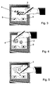
- the Fig. 3 to 5 show examples of the input of graphic information about the input unit 2 while it is in the graphic input mode.
- Fig. 3 the additional information 4 is entered in the form of a handwritten text or a signature.
- the input takes place here - as indicated - with the help of a stylus.
- the input mode is ended.
- the display of the input unit 2 is then returned to the in Fig. 2 displayed state reset.
- the input graphical additional information can now be stored together with the X-ray information read, preferably in a memory of the computer system 20 (see Fig. 1 ).
- the additional graphic information 4 can also take the form of any national characters and / or symbols.
- the display and input unit is preferably provided with a function in which the displayed icons, symbols or text information can be arbitrarily reconfigured and thus adapted to particular applications or the respective national language.
- the fourth icon 9 can be changed to a corresponding Asian character for "delete”.
- the additional information 4 can also be entered in the form of an image and / or in the form of symbols or highlights to a respective displayed image.
- the graphical input unit 2 is operated so that it serves both for easy control of the read-out device 1 and / or the input unit 2 by touching pictograms as well as for simple and quick handwritten input of additional graphic information. As a result, it is particularly suitable for the radiological diagnosis of emergency patients.
Landscapes
- Life Sciences & Earth Sciences (AREA)
- Health & Medical Sciences (AREA)
- Engineering & Computer Science (AREA)
- Medical Informatics (AREA)
- Pathology (AREA)
- Heart & Thoracic Surgery (AREA)
- High Energy & Nuclear Physics (AREA)
- Physics & Mathematics (AREA)
- Nuclear Medicine, Radiotherapy & Molecular Imaging (AREA)
- Optics & Photonics (AREA)
- Veterinary Medicine (AREA)
- Radiology & Medical Imaging (AREA)
- Biomedical Technology (AREA)
- Biophysics (AREA)
- Molecular Biology (AREA)
- Surgery (AREA)
- Animal Behavior & Ethology (AREA)
- General Health & Medical Sciences (AREA)
- Public Health (AREA)
- Human Computer Interaction (AREA)
- Radiography Using Non-Light Waves (AREA)
- Apparatus For Radiation Diagnosis (AREA)
- Medical Treatment And Welfare Office Work (AREA)
Description
- Die Erfindung betrifft ein System sowie ein entsprechendes Verfahren zum Auslesen von in einer Speicherleuchtstoffschicht gespeicherter Röntgeninformation gemäß dem Oberbegriff des Anspruchs 1 bzw. 10.
- Eine Möglichkeit zur Aufzeichnung von Röntgenbildern besteht darin, die durch ein Objekt, beispielsweise einen Patienten, hindurch tretende Röntgenstrahlung als latentes Bild in einer so genannten Speicherleuchtstoffschicht zu speichern. Zum Auslesen des latenten Bildes wird die Speicherleuchtstoffschicht mit Stimulationslicht bestrahlt und dabei zur Aussendung von Emissionslicht angeregt. Das Emissionslicht, dessen Intensität dem in der Speicherleuchtstoffschicht gespeicherten Bild entspricht, wird von einem optischen Detektor erfasst und in elektrische Signale umgewandelt. Die elektrischen Signale werden nach Bedarf weiterverarbeitet und schließlich für eine Auswertung, insbesondere zu medizinisch-diagnostischen Zwecken, bereitgestellt, indem sie an einem entsprechenden Ausgabegerät, wie z. B. einem Monitor oder Drucker, ausgegeben werden.
- In bekannten Systemen und Verfahren werden vor und/oder nach einer Röntgenaufnahme an einer Dateneingabestation, einer so genannten ID-Station, zusätzliche Informationen zur Identität des Patienten, zur Röntgenaufnahme, zum anschließenden Auslesen des latenten Bildes und/oder Verarbeiten der ausgelesenen Röntgeninformationen eingegeben.
- Aus
EP 1 415 594 A1 ist bekannt, über einen sog. persönlichen digitalen Assistenten (PDA) eine Identifizierung des jeweiligen Bedieners vorzunehmen sowie radiographische Bedingungen und Anweisungen an ein Radiographiegerät weiterzugeben. Der PDA kann außerdem radiographische Auftragsinformationen von einer Informationsmanagement-Einrichtung empfangen. Die vom PDA empfangenen radiographischen Auftragsinformationen werden einem medizinischen Bild, das aus einer in einer Kassette befindlichen Speicherleuchtstoffplatte ausgelesen wird, zugeordnet und mit diesem in einer Datenbank gespeichert. - In bestimmten Anwendungsfällen, insbesondere bei Notfällen, sind Zeitverzögerungen bei der Eingabe von zusätzlichen Informationen möglichst zu vermeiden. Die aus dem Stand der Technik bekannten Systeme bzw. Verfahren sind für solche Anwendungsfälle somit nur bedingt geeignet.
- Es ist Aufgabe der Erfindung, ein System sowie ein entsprechendes Verfahren zum Auslesen von in einer Speicherleuchtstoffschicht gespeicherter Röntgeninformation anzugeben, bei welchem eine möglichst einfache und schnelle Eingabe von Zusatzinformationen ermöglicht wird.
- Diese Aufgabe wird gemäß Anspruch 1 bzw. 10 dadurch gelöst, dass zur Eingabe einer Zusatzinformation eine graphische Eingabeeinheit vorgesehen ist, in welcher die Zusatzinformation durch einen Bediener in graphischer Form handschriftlich eingegeben werden kann. Darüber hinaus ist eine Zuordnungseinrichtung zur Zuordnung der in der graphischen Eingabeeinheit handschriftlich eingegebenen Zusatzinformation zur ausgelesenen Röntgeninformation vorgesehen.
- Durch die Verwendung einer graphischen Eingabeeinheit wird eine - im Vergleich zu der üblicherweise per Tastatur erfolgende Dateneingabe - einfachere und schnellere Eingabe von Zusatzinformationen ermöglicht. Das erfindungsgemäße System bzw. Verfahren ist daher gerade bei der radiologischen Diagnose von Notfallpatienten von besonderem Vorteil. Darüber hinaus ist die eingebbare graphische Zusatzinformation in Form und Inhalt frei gestaltbar und nicht an spezielle Datenfelder oder Datenformate gebunden. Auf diese Weise können den ausgelesenen Röntgeninformationen Zusatzinformationen, wie z.B. Skizzen oder beliebig gestaltete Zeichen, zugeordnet werden, die bei der Dateneingabe in aus dem Stand der Technik bekannten Systemen nicht berücksichtigt werden können.
- Erfindungsgemäß ist die Eingabeeinheit zur handschriftlichen Eingabe der Zusatzinformation durch den Bediener, insbesondere in Form von Text, Bildern oder Symbolen ausgebildet. Die handschriftliche Eingabe stellt eine besonders einfache und direkte Möglichkeit zur Eingabe der Zusatzinformation dar. Beispielsweise kann hierdurch auch eine handschriftliche Signatur durch den Bediener, z.B. in Form einer vollständigen Unterschrift oder eines Namenskürzels, vorgenommen werden.
- Vorzugsweise ist die Eingabeeinheit als berührungsempfindliche Eingabeeinheit ausgebildet, in welche die Zusatzinformation durch Berührung der Eingabeeinheit, insbesondere durch Schreib- oder Zeichenbewegungen auf der Eingabeeinheit, eingegeben werden kann. Die Eingabe kann entweder durch einen Finger oder die Hand des Bedieners oder unter Zuhilfenahme eines geeigneten Eingabestiftes erfolgen.
- Vorzugsweise ist eine Anzeigeeinheit vorgesehen, welche zum Anzeigen der Zusatzinformation bei deren Eingabe ausgebildet ist. Die Anzeigeeinheit kann dabei entweder separat von der Eingabeeinheit angeordnet sein oder aber mit dieser zusammen in einer kombinierten Anzeige- und Eingabeeinheit integriert sein. Eine solche kombinierte Anzeige- und Eingabeeinheit wird auch als Touch Screen oder Touch Panel bezeichnet. Dies hat den Vorteil, dass der Bediener die Zusatzinformation bei deren Eingabe unmittelbar überprüfen kann.
- Die Anzeige- und Eingabeeinheit kann zusätzlich zur Darstellung von Piktogrammen ausgebildet sein, welche unterschiedliche Betriebsmodi der Ausleseeinrichtung und/oder der Eingabeeinheit symbolisieren und durch Berührung der Eingabeeinheit im Bereich der dargestellten Piktogramme ausgewählt werden können. Die Berührung erfolgt hierbei ebenfalls per Finger und/oder Eingabestift. Hierdurch wird zusätzlich die Steuerung der Ausleseeinrichtung bzw. die Menüführung in der Anzeige- und Eingabeeinheit vereinfacht.
- In einer Variante der Erfindung ist eine Umwandlungseinrichtung zur Umwandlung der Zusatzinformation von der graphischen Form in eine zeichenorientierte Form vorgesehen und die Zuordnungseinrichtung zur Zuordnung der Zusatzinformation in der zeichenorientierten Form zur ausgelesenen Röntgeninformation ausgebildet. Die Umwandlungseinrichtung wandelt hierbei die handschriftlich eingegebenen Zeichen vorzugsweise in alphanumerische Zeichenfolgen um, welche dann den ausgelesenen Röntgeninformationen zugeordnet werden. Durch die Umwandlung der graphischen Zusatzinformation in eine zeichenorientierte Form wird der Speicherplatzbedarf für die Speicherung der Zusatzinformation reduziert.
- Vorzugsweise wird die ausgelesene Röntgeninformation zusammen mit der eingegebenen graphischen Zusatzinformation dargestellt. Die Darstellung erfolgt insbesondere auf einem Bildschirm (Monitor) oder einem Ausdruck (Hardcopy). Die eingegebene Zusatzinformation steht somit zusammen mit der dargestellten Röntgeninformation zur Verfügung und kann unmittelbar zu deren Interpretation, Analyse oder anderen Zwecken herangezogen werden. Dies ist insbesondere bei der Diagnose von Notfallpatienten von Vorteil, bei der neben einer schnellen Eingabe der Zusatzinformation eine möglichst übersichtliche Darstellung der zur Verfügung stehenden zusätzlichen Informationen gefordert ist.
- Es ist außerdem bevorzugt, dass die Eingabeeinheit in die Ausleseeinrichtung integriert ist. Hierdurch wird erreicht, dass die graphische Zusatzinformation von einem Bediener eingegebenen werden kann, wenn sich dieser im Bereich der Ausleseeinrichtung aufhält, insbesondere bei der Eingabe bzw. Entnahme der Kassette, in welcher sich die auszulesende Speicherleuchtstoffschicht befindet. Dadurch wird ein separater Gang zu einer Dateneingabestation, beispielsweise einer ID-Station, überflüssig, und die Dateneingabe kann vielmehr sofort an der Ausleseeinrichtung erfolgen.
- Weitere Merkmale und Vorteile der Erfindung ergeben sich aus der folgenden Beschreibung bevorzugter Ausführungsformen und Anwendungsbeispiele, wobei Bezug auf die beigefügten Zeichnungen genommen wird.
- Es zeigen:
- Fig. 1
- ein Ausführungsbeispiel des erfindungsgemäßen Systems;
- Fig. 2
- ein Ausführungsbeispiel einer Eingabeeinheit;
- Fig. 3
- ein erstes Beispiel für die Eingabe von graphischer Information;
- Fig. 4
- ein zweites Beispiel für die Eingabe von graphischer Information; und
- Fig. 5
- ein drittes Beispiel für die Eingabe von graphischer Information.
-
Fig. 1 zeigt ein Ausführungsbeispiel des erfindungsgemäßen Systems, das eine Ausleseeinrichtung 1 zum Auslesen von Röntgeninformationen aus Speicherleuchtstoffschichten umfasst. - Vor dem Auslesen wird eine Kassette 15, in welcher sich eine Speicherleuchtstoffschicht befindet, in eine Kassettenaufnahme 12 der Ausleseeinrichtung 1 eingegeben. In dieser Position wird die Kassette 15 geöffnet und die darin befindliche Speicherleuchtstoffschicht entnommen und in das Innere der Ausleseeinrichtung 1 befördert. Dort wird die Speicherleuchtstoffschicht ausgelesen.
- Zum Auslesen ist vorzugsweise ein so genannter Zeilenscanner vorgesehen, bei welchem jeweils eine ganze Zeile der Speicherleuchtstoffschicht mit Stimulationslicht bestrahlt wird und das hierbei erzeugte Emissionslicht mit einem zeilenförmigen Detektorarray erfasst wird. Einzelheiten zum Aufbau eines solchen Zeilenscanners können beispielsweise aus der
US 6,373,074 B1 entnommen werden. Alternativ kann hierfür auch ein so genannter Flying Spot-Scanner eingesetzt werden, wie er beispielsweise in derUS 6,501,088 B1 beschrieben ist. - Nach dem Auslesevorgang werden in der Speicherleuchtstoffschicht verbleibende Restinformationen durch Bestrahlung der Speicherleuchtstoffschicht mit Licht einer geeigneten Spektralverteilung und Intensität gelöscht. Nach dem Löschen wird die Speicherleuchtstoffschicht wieder zurück in die Kassette 15 transportiert und kann von dem Bediener entnommen und für weitere Röntgenaufnahmen bereitgestellt werden.
- Die Ausleseeinrichtung 1 weist eine Statusanzeige 3 zur Anzeige des jeweiligen Betriebszustands auf. Leuchtet oder blinkt die Statusanzeige 3 beispielsweise grün, so wird signalisiert, dass die Ausleseeinrichtung 1 betriebsbereit bzw. vorübergehend mit dem Auslesen und Löschen einer Speicherleuchtstoffschicht beschäftigt ist. Leuchtet oder blinkt dagegen die Statusanzeige 3 rot, so wird das Vorliegen eines Fehlers bzw. die Durchführung eines Start- oder Selbsttestprogramms signalisiert.
- Neben der Statusanzeige 3 weist die Ausleseeinrichtung 1 eine Eingabeeinheit 2 auf, über welche durch den Bediener Zusatzinformationen eingegeben werden können. Die Eingabeeinheit 2 ist hierbei erfindungsgemäß als graphische Eingabeeinheit ausgebildet, so dass die Zusatzinformation durch den Bediener in graphischer Form eingegeben werden kann. Die Eingabe der Zusatzinformation erfolgt dabei vorzugsweise unmittelbar vor oder nach dem Auslesen oder aber auch während des Auslesens der Speicherleuchtstoffschicht in der Ausleseeinrichtung 1.
- Die eingegebene Zusatzinformation wird erfindungsgemäß den jeweils ausgelesenen Röntgeninformationen zugeordnet. Dies erfolgt vorzugsweise durch eine Übertragung sowohl der ausgelesenen Röntgeninformation als auch der eingegebenen Zusatzinformation über eine Datenleitung 11 zu einem Computersystem 20, in welchem ein Speicher zur Speicherung dieser Informationen vorgesehen ist.
- Die Zuordnung der Zusatzinformation zu den jeweiligen Röntgeninformationen kann beispielsweise durch Speichern der Zusatzinformation und der zugehörigen Röntgeninformationen in einem gemeinsamen Datenfeld im Speicher des Computersystems 20 erfolgen. Alternativ oder zusätzlich können beide Informationen aber auch in unterschiedlichen Datenfeldern gespeichert werden, wobei eine Zuordnung beispielsweise durch geeignete Adresszeiger erreicht wird.
- Das erfindungsgemäße System weist darüber hinaus einen Bildschirm 25 auf, auf dem die ausgelesene Röntgeninformation in Form eines Röntgenbildes 26 zusammen mit der eingegebenen Zusatzinformation 4 dargestellt wird. Im gezeigten Beispiel wird die Zusatzinformation 4 in einem gesonderten Darstellungsfeld 30 im linken unteren Bereich des dargestellten Röntgenbildes 26 wiedergegeben. Zur Verbesserung der Anschaulichkeit sind das Darstellungsfeld 30 und die darin dargestellte Zusatzinformation 4 zusätzlich vergrößert dargestellt. Die Größe und Anordnung des Darstellungsfeldes 30 für die eingegebene Zusatzinformation 4 im Röntgenbild 26 kann vom Bediener mittels geeigneter Bedienelemente 28, wie z. B. Tastatur und/oder Computermaus, beliebig verändert werden.
-
Fig. 2 zeigt ein Ausführungsbeispiel einer Eingabeeinheit 2, die zusammen mit der Statusanzeige 3 auf einer Platine 13 angeordnet ist. Durch die Kombination der beiden Komponenten auf einer gemeinsamen Platine 13 wird die Integration sowohl der Eingabeeinheit 2 als auch der Statusanzeige 3 in das Gehäuse der Ausleseeinrichtung 1 sowie die schaltungstechnische Realisierung vereinfacht. - Die Eingabeeinheit 2 ist in dem dargestellten Beispiel mit einer Anzeigeeinheit kombiniert und bildet zusammen mit dieser eine Anzeige- und Eingabeeinheit, welche auch als Touch Screen oder Touch Panel bezeichnet wird.
- Im Bereich der Eingabeeinheit 2 werden in der Anzeigeeinheit unterschiedliche Piktogramme 5, 6 und 7 sowie ein Symbol 10 angezeigt. Durch Berührung der Eingabeeinheit 2 im Bereich eines Piktogramms 5, 6 bzw. 7 wird die dem jeweiligen Piktogramm 5, 6 bzw. 7 zugeordnete Funktion ausgewählt und ausgeführt.
- So wird z. B. durch Berühren der Eingabeeinheit 2 im Bereich des ersten Piktogramms 7 ein Betriebsmodus ausgewählt, in welchem die in der Kassette 15 befindliche Speicherleuchtstoffschicht sofort in die Ausleseeinrichtung 1 eingegeben und ausgelesen werden kann, ohne vorher oder anschließend die Eingabe von Daten zum Patienten, zur Röntgenaufnahme und/oder Weiterverarbeitung der ausgelesenen Röntgeninformation zu erfordern. Dieser Betriebsmodus wird auch als Emergency Case bezeichnet, da er insbesondere bei Notfällen, in denen keine Zeit für die Eingabe der o.g. Daten ist, Verwendung findet.
- Durch Betätigen des zweiten Piktogramms 6 kann eine Übersicht über weitere Funktionen bzw. Betriebsmodi der Eingabeeinrichtung 2 und/oder Ausleseeinrichtung 1 abgerufen werden.
- Durch Anwählen des dritten Piktogramms 5 wird die Eingabeeinheit 2 in einen graphischen Eingabemodus versetzt, in welchem der Bediener Zusatzinformationen in graphischer Form eingeben kann.
- Das dargestellte Symbol 10 in Form eines Hakens zeigt die allgemeine Betriebsbereitschaft der Ausleseeinrichtung 1 an.
- Die aktive Anzeigefläche der Eingabeeinheit 2 weist eine seitliche Abmessung auf, welche typischerweise zwischen 50 und 100 mm liegt. Die Anzahl der Bildpunkte (Pixel) liegt typischerweise zwischen 20.000 und 100.000. Typische Abmessungen eines Bildpunktes liegen im Bereich zwischen 0,2 und 0,5 mm. Im dargestellten Beispiel der
Fig. 2 beträgt die aktive Anzeigefläche 56x56 mm, wobei die einzelnen Bildpunkte eine Fläche von 0,35x0,35 mm abdecken. Insgesamt umfasst die aktive Anzeigefläche somit 160x160=25.600 Pixel. Jedem Bildpunkt der Anzeigeeinheit ist ein berührungsempfindlicher Bereich der Eingabeeinheit 2 zugeordnet. - Die
Fig. 3 bis 5 zeigen Beispiele für die Eingabe von graphischer Information über die Eingabeeinheit 2, während sich diese im graphischen Eingabemodus befindet. - In
Fig. 3 wird die Zusatzinformation 4 in Form eines handschriftlichen Textes oder einer Unterschrift eingegeben. Die Eingabe erfolgt hierbei - wie angedeutet - unter Zuhilfenahme eines Eingabestiftes. - Durch Berühren eines vierten Piktogramms 9 kann die aktuell eingegebene graphische Zusatzinformation wieder gelöscht werden und ggf. erneut eingegeben werden.
- Durch Berühren des fünften Piktogramms 8 wird der Eingabemodus beendet. Die Anzeige der Eingabeeinheit 2 wird dann wieder in den in
Fig. 2 dargestellten Zustand zurückgesetzt. Die eingegebene graphische Zusatzinformation kann nun zusammen mit der ausgelesenen Röntgeninformation gespeichert werden, vorzugsweise in einem Speicher des Computersystems 20 (sieheFig. 1 ). - Wie das in
Fig. 4 dargestellte zweite Beispiel zeigt, kann die graphische Zusatzinformation 4 auch in Form beliebiger nationaler Schriftzeichen und/oder Symbole erfolgen. Die Anzeige- und Eingabeeinheit ist vorzugsweise mit einer Funktion versehen, in welcher die angezeigten Piktogramme, Symbole oder Textinformationen beliebig umgestaltet und somit an besondere Anwendungsfälle oder die jeweilige Landessprache angepasst werden können. So kann beispielsweise das vierte Piktogramm 9 in ein entsprechendes asiatisches Schriftzeichen für "Löschen" geändert werden. - Wie das dritte Beispiel in
Fig. 5 zeigt, kann die Zusatzinformation 4 auch in Form eines Bildes und/oder in Form von Symbolen oder Hervorhebungen zu einem jeweils angezeigten Bild eingegeben werden. - Bei den dargestellten Ausführungsbeispielen wird die graphische Eingabeeinheit 2 so betrieben, dass sie sowohl zur einfachen Steuerung der Ausleseeinrichtung 1 und/oder der Eingabeeinheit 2 durch Berühren von Piktogrammen als auch zur einfachen und schnellen handschriftlichen Eingabe einer graphischen Zusatzinformation dient. Hierdurch ist sie für die radiologische Diagnose von Notfallpatienten besonders geeignet.
Claims (16)
- System zum Auslesen von in einer Speicherleuchtstoffschicht gespeicherter Röntgeninformation mit- einer Ausleseeinrichtung (1) zum Auslesen der in der Speicherleuchtstoffschicht gespeicherten Röntgeninformation und- einer Eingabeeinheit (2) zur Eingabe einer Zusatzinformation durch einen Bediener, wobei die Eingabeeinheit (2) als graphische Eingabeeinheit ausgebildet ist,- einem Computersystem (20) mit einem Speicher- einer Zuordnungseinrichtung zur Zuordnung der durch den Bediener in der Eingabeeinheit (2) in graphischer Form handschriftlich eingegebenen Zusatzinformation (4) zur ausgelesenen Röntgeninformation,dadurch gekennzeichnet, dass
die Zuordnung dadurch erfolgt, dass die ausgelesene Röntgeninformation und die handschriftlich eingegebene Zusatzinformation (4) in graphischer Form im Speicher des Computersystems (20) gespeichert werden. - System nach Anspruch 1, wobei die Eingabeeinheit (2) zur handschriftlichen Eingabe der Zusatzinformation (4) in Form von Text, Bildern, Symbolen oder einer Signatur ausgebildet ist.
- System nach Anspruch 1 oder 2, wobei die Eingabeeinheit (2) als berührungsempfindliche Eingabeeinheit ausgebildet ist, in welche die Zusatzinformation durch Berührung der Eingabeeinheit (2), insbesondere durch Schreib- oder Zeichenbewegungen auf der Eingabeeinheit (2), eingegeben werden kann.
- System nach einem der vorangehenden Ansprüche, wobei eine Anzeigeeinheit zum Anzeigen der Zusatzinformation (4) bei deren Eingabe vorgesehen ist.
- System nach Anspruch 3 und 4, wobei die Anzeigeeinheit und die Eingabeeinheit (2) in einer Anzeige- und Eingabeeinheit integriert sind, welche insbesondere als Touch Screen ausgebildet ist.
- System nach Anspruch 5, wobei die Anzeige- und Eingabeeinheit zur Darstellung von Piktogrammen (5 bis 9) ausgebildet ist, welche unterschiedliche Betriebsmodi der Ausleseeinrichtung (1) und/oder der Eingabeeinheit (2) symbolisieren und durch Berührung der Eingabeeinheit (2) ausgewählt werden können.
- System nach einem der vorangehenden Ansprüche, wobei eine Umwandlungseinrichtung zur Umwandlung der Zusatzinformation (4) von der graphischen Form in eine zeichenorientierte Form vorgesehen ist und die Zuordnungseinrichtung zur Zuordnung der Zusatzinformation in der zeichenorientierten Form zur Röntgeninformation ausgebildet ist.
- System nach einem der vorangehenden Ansprüche, wobei eine Darstellungseinrichtung, insbesondere ein Bildschirm (25) oder ein Drucker, zu einer Darstellung (26, 30) der ausgelesenen Röntgeninformation zusammen mit der eingegebenen Zusatzinformation (4) vorgesehen ist.
- System nach einem der vorangehenden Ansprüche, wobei die Eingabeeinheit (2) in die Ausleseeinrichtung (1) integriert ist.
- Verfahren zum Auslesen von in einer Speicherleuchtstoffschicht gespeicherter Röntgeninformation mit folgenden Schritten:- Eingabe einer Zusatzinformation in eine Eingabeeinheit (2) durch einen Bediener und- Auslesen der in der Speicherleuchtstoffschicht gespeicherten Röntgeninformation,wobei:- die Zusatzinformation (4) durch den Bediener in graphischer Form in die Eingabeeinheit (2) handschriftlich eingegeben wird und- die in der Eingabeeinheit (2) in graphischer Form handschriftlich eingegebene Zusatzinformation der ausgelesenen Röntgeninformation zugeordnet wird,dadurch gekennzeichnet, dass
die ausgelesene Röntgeninformation und die handschriftlich eingegebene Zusatzinformation (4) in graphischer Form in einem Speicher eines Computersystems (20) gespeichert werden. - Verfahren nach Anspruch 10, wobei die handschriftliche Eingabe der Zusatzinformation (4) in die Eingabeeinheit (2) in Form von Text, Bildern, Symbolen oder einer Signatur erfolgt.
- Verfahren nach Anspruch 10 oder 11, wobei die Zusatzinformation (4) durch Berührung der Eingabeeinheit (2), insbesondere durch Schreib- oder Zeichenbewegungen auf der Eingabeeinheit (2), eingegeben wird.
- Verfahren nach einem der Ansprüche 10 bis 12, wobei die Zusatzinformation (4) bei deren Eingabe angezeigt wird.
- Verfahren nach Anspruch 13, wobei Piktogramme (5 bis 9), welche unterschiedliche Betriebsmodi der Ausleseeinrichtung (1) und/oder der Eingabeeinheit (2) symbolisieren, angezeigt und durch Berührung der Eingabeeinheit (2) ausgewählt werden.
- Verfahren nach einem der Ansprüche 10 bis 14, wobei die Zusatzinformation von der graphischen Form in eine zeichenorientierte Form umgewandelt wird, in welcher sie der Röntgeninformation zugeordnet wird.
- Verfahren nach einem der Ansprüche 10 bis 15, wobei die ausgelesene Röntgeninformation (26) zusammen mit der eingegebenen Zusatzinformation (4, 30), insbesondere auf einem Bildschirm (25) oder einem Ausdruck, dargestellt wird.
Priority Applications (4)
| Application Number | Priority Date | Filing Date | Title |
|---|---|---|---|
| DE502004010009T DE502004010009D1 (de) | 2004-12-20 | 2004-12-20 | System und Verfahren zum Auslesen von in einer Speicherleuchtstoffschicht gespeicherter Röntgeninformation |
| AT04106745T ATE441357T1 (de) | 2004-12-20 | 2004-12-20 | System und verfahren zum auslesen von in einer speicherleuchtstoffschicht gespeicherter ríntgeninformation |
| EP04106745A EP1671587B1 (de) | 2004-12-20 | 2004-12-20 | System und Verfahren zum Auslesen von in einer Speicherleuchtstoffschicht gespeicherter Röntgeninformation |
| US11/299,413 US7227168B2 (en) | 2004-12-20 | 2005-12-12 | System and method for reading out X-ray information stored in a phosphor layer |
Applications Claiming Priority (1)
| Application Number | Priority Date | Filing Date | Title |
|---|---|---|---|
| EP04106745A EP1671587B1 (de) | 2004-12-20 | 2004-12-20 | System und Verfahren zum Auslesen von in einer Speicherleuchtstoffschicht gespeicherter Röntgeninformation |
Publications (2)
| Publication Number | Publication Date |
|---|---|
| EP1671587A1 EP1671587A1 (de) | 2006-06-21 |
| EP1671587B1 true EP1671587B1 (de) | 2009-09-02 |
Family
ID=34930091
Family Applications (1)
| Application Number | Title | Priority Date | Filing Date |
|---|---|---|---|
| EP04106745A Expired - Lifetime EP1671587B1 (de) | 2004-12-20 | 2004-12-20 | System und Verfahren zum Auslesen von in einer Speicherleuchtstoffschicht gespeicherter Röntgeninformation |
Country Status (4)
| Country | Link |
|---|---|
| US (1) | US7227168B2 (de) |
| EP (1) | EP1671587B1 (de) |
| AT (1) | ATE441357T1 (de) |
| DE (1) | DE502004010009D1 (de) |
Family Cites Families (11)
| Publication number | Priority date | Publication date | Assignee | Title |
|---|---|---|---|---|
| EP0077999B1 (de) * | 1981-10-26 | 1989-09-06 | Fuji Photo Film Co., Ltd. | Datenverarbeitungssystem für ein Strahlenbild-Wiedergabegerät |
| JP3851699B2 (ja) * | 1997-02-06 | 2006-11-29 | 富士写真フイルム株式会社 | 画像解析装置 |
| DE19752925C2 (de) * | 1997-11-28 | 2003-11-27 | Agfa Gevaert Ag | Vorrichtung zum Auslesen von einer in einem Phosphorträger abgespeicherten Information und Röntgenkassette |
| JP3619027B2 (ja) * | 1998-09-30 | 2005-02-09 | キヤノン株式会社 | X線撮影装置、x線撮影システム、x線画像処理方法、及びコンピュータ読み取り可能な記録媒体 |
| EP1065523A3 (de) * | 1999-07-02 | 2006-04-05 | Agfa-Gevaert | Verfahren und Vorrichtung zum Auslesen von Strahlungsbildern |
| US7054472B1 (en) * | 1999-10-12 | 2006-05-30 | Fuji Photo Film Co., Ltd. | Image sending apparatus and image transmission information display apparatus |
| JP3893827B2 (ja) * | 1999-11-26 | 2007-03-14 | コニカミノルタホールディングス株式会社 | X線画像撮影システム |
| JP2003220056A (ja) * | 2002-01-29 | 2003-08-05 | Konica Corp | 医用画像表示装置、画像取得表示装置及び該装置における画像表示方法並びに表示形式選択プログラム |
| JP2004147907A (ja) * | 2002-10-31 | 2004-05-27 | Konica Minolta Holdings Inc | 医用画像撮影システム、医用画像撮影装置、医用画像撮影方法及びプログラム |
| DE10255958B4 (de) * | 2002-11-29 | 2006-09-28 | Siemens Ag | Bedieneinrichtung für ein diagnostisches Bildgebungsgerät |
| EP1544672B1 (de) * | 2003-12-17 | 2008-11-19 | Agfa-Gevaert HealthCare GmbH | Bildträger zur Speicherung von Röntgeninformation sowie System und Verfahren zur Bearbeitung eines solchen Bildträgers |
-
2004
- 2004-12-20 DE DE502004010009T patent/DE502004010009D1/de not_active Expired - Lifetime
- 2004-12-20 AT AT04106745T patent/ATE441357T1/de not_active IP Right Cessation
- 2004-12-20 EP EP04106745A patent/EP1671587B1/de not_active Expired - Lifetime
-
2005
- 2005-12-12 US US11/299,413 patent/US7227168B2/en not_active Expired - Fee Related
Also Published As
| Publication number | Publication date |
|---|---|
| ATE441357T1 (de) | 2009-09-15 |
| EP1671587A1 (de) | 2006-06-21 |
| DE502004010009D1 (de) | 2009-10-15 |
| US20060131524A1 (en) | 2006-06-22 |
| US7227168B2 (en) | 2007-06-05 |
Similar Documents
| Publication | Publication Date | Title |
|---|---|---|
| DE69408439T2 (de) | Verfahren zur Identifizierung eines Strahlungsbildes | |
| DE69331623T2 (de) | Automatische Leitwegsuche von digitalen Röntgenbildern zum gewählten Ziel | |
| DE10241400B4 (de) | Verfahren zum Verwalten eines sequentiellen Prozesses unter Verwendung einer graphischen Benutzerschnittstelle | |
| DE69430164T2 (de) | Röntgenstrahlabbildunggerät und Verfahren für Diagnosezwecke | |
| DE60038155T2 (de) | Röntgenbildsystem | |
| DE10108295B4 (de) | Zahnidentifikation auf digitalen Röntgenaufnahmen und Zuordnung von Informationen zu digitalen Röntgenaufnahmen | |
| DE3414518C2 (de) | ||
| DE69419984T2 (de) | Echtzeit-Einstellung von Fensterbreite und Pegel in einer radiographischen Arbeitsstation | |
| EP1304653B9 (de) | System und Verfahren zur Anzeige von Bildern | |
| DE102018212331A1 (de) | Strahlungstransmissions- und Fluoreszenz-Computertomographie (CT) -Bildgebungssystem und -Verfahren | |
| DE10354899B4 (de) | Röntgenvorrichtung und Verfahren zum Herstellen eines Röntgenbilddatensatzes | |
| DE10160611A1 (de) | Bildgebende medizinische Untersuchungseinrichtung | |
| DE19919151A1 (de) | Vorrichtung und Verfahren zur Durchführung einer skalierbaren Mehrschnitt-Computer-Tomographie-Abtastung | |
| DE10119760A1 (de) | Abbildungssystem mit einer Einrichtung zum Erzeugen, Verwalten und Auswählen von Untersuchungsbeschreibungen unter Verwendung einer Liste von Untersuchungsbeschreibungen | |
| DE4340228A1 (de) | Einrichtung und Verfahren zum automatischen Nachführen einer gezoomten Abtastfläche in einem medizinischen Kamerasystem | |
| EP0993239A1 (de) | Röntgeneinrichtung | |
| DE69227008T2 (de) | Verfahren und Vorrichtung zum Herstellen eines Histogramms in der digitalen Bildverarbeitung mittels statistischer Pixelabtastung | |
| DE69409095T2 (de) | System zur Wiedergabe eines individuell gestalteter Strahlungsbildes | |
| EP1544673B1 (de) | Bildträger zur Speicherung von Röntgeninformation sowie System zur Bearbeitung eines solchen Bildträgers | |
| EP1321099B1 (de) | Röntgeneinrichtung mit einer Speicheranordnung für Aufnahmeparameter von Röntgenaufnahmen | |
| DE69523893T2 (de) | Reproduktion oder Anzeige von medizinischen Bildern mit konfigurierbarem Textbereich | |
| DE102014226287B4 (de) | Verfahren zur Bedienung eines medizinischen Geräts und System zur Bedienung eines medizinischen Geräts | |
| JP2003284709A (ja) | 画像取得表示装置及び該装置を用いた撮影条件の編集方法並びに撮影条件配列プログラム | |
| EP1544672B1 (de) | Bildträger zur Speicherung von Röntgeninformation sowie System und Verfahren zur Bearbeitung eines solchen Bildträgers | |
| EP1544674B1 (de) | Verfahren zur Bearbeitung eines Bildträgers zur Speicherung von Röntgeninformation |
Legal Events
| Date | Code | Title | Description |
|---|---|---|---|
| PUAI | Public reference made under article 153(3) epc to a published international application that has entered the european phase |
Free format text: ORIGINAL CODE: 0009012 |
|
| AK | Designated contracting states |
Kind code of ref document: A1 Designated state(s): AT BE BG CH CY CZ DE DK EE ES FI FR GB GR HU IE IS IT LI LT LU MC NL PL PT RO SE SI SK TR |
|
| AX | Request for extension of the european patent |
Extension state: AL BA HR LV MK YU |
|
| 17P | Request for examination filed |
Effective date: 20061221 |
|
| R17P | Request for examination filed (corrected) |
Effective date: 20061221 |
|
| AKX | Designation fees paid |
Designated state(s): AT BE BG CH CY CZ DE DK EE ES FI FR GB GR HU IE IS IT LI LT LU MC NL PL PT RO SE SI SK TR |
|
| 17Q | First examination report despatched |
Effective date: 20071029 |
|
| RAP1 | Party data changed (applicant data changed or rights of an application transferred) |
Owner name: AGFA-GEVAERT HEALTHCARE GMBH |
|
| GRAP | Despatch of communication of intention to grant a patent |
Free format text: ORIGINAL CODE: EPIDOSNIGR1 |
|
| GRAS | Grant fee paid |
Free format text: ORIGINAL CODE: EPIDOSNIGR3 |
|
| GRAA | (expected) grant |
Free format text: ORIGINAL CODE: 0009210 |
|
| AK | Designated contracting states |
Kind code of ref document: B1 Designated state(s): AT BE BG CH CY CZ DE DK EE ES FI FR GB GR HU IE IS IT LI LT LU MC NL PL PT RO SE SI SK TR |
|
| REG | Reference to a national code |
Ref country code: CH Ref legal event code: EP |
|
| REG | Reference to a national code |
Ref country code: IE Ref legal event code: FG4D Free format text: LANGUAGE OF EP DOCUMENT: GERMAN |
|
| REF | Corresponds to: |
Ref document number: 502004010009 Country of ref document: DE Date of ref document: 20091015 Kind code of ref document: P |
|
| PG25 | Lapsed in a contracting state [announced via postgrant information from national office to epo] |
Ref country code: SE Free format text: LAPSE BECAUSE OF FAILURE TO SUBMIT A TRANSLATION OF THE DESCRIPTION OR TO PAY THE FEE WITHIN THE PRESCRIBED TIME-LIMIT Effective date: 20090902 Ref country code: FI Free format text: LAPSE BECAUSE OF FAILURE TO SUBMIT A TRANSLATION OF THE DESCRIPTION OR TO PAY THE FEE WITHIN THE PRESCRIBED TIME-LIMIT Effective date: 20090902 Ref country code: LT Free format text: LAPSE BECAUSE OF FAILURE TO SUBMIT A TRANSLATION OF THE DESCRIPTION OR TO PAY THE FEE WITHIN THE PRESCRIBED TIME-LIMIT Effective date: 20090902 |
|
| NLV1 | Nl: lapsed or annulled due to failure to fulfill the requirements of art. 29p and 29m of the patents act | ||
| LTIE | Lt: invalidation of european patent or patent extension |
Effective date: 20090902 |
|
| PG25 | Lapsed in a contracting state [announced via postgrant information from national office to epo] |
Ref country code: SI Free format text: LAPSE BECAUSE OF FAILURE TO SUBMIT A TRANSLATION OF THE DESCRIPTION OR TO PAY THE FEE WITHIN THE PRESCRIBED TIME-LIMIT Effective date: 20090902 Ref country code: NL Free format text: LAPSE BECAUSE OF FAILURE TO SUBMIT A TRANSLATION OF THE DESCRIPTION OR TO PAY THE FEE WITHIN THE PRESCRIBED TIME-LIMIT Effective date: 20090902 Ref country code: PL Free format text: LAPSE BECAUSE OF FAILURE TO SUBMIT A TRANSLATION OF THE DESCRIPTION OR TO PAY THE FEE WITHIN THE PRESCRIBED TIME-LIMIT Effective date: 20090902 |
|
| PG25 | Lapsed in a contracting state [announced via postgrant information from national office to epo] |
Ref country code: CY Free format text: LAPSE BECAUSE OF FAILURE TO SUBMIT A TRANSLATION OF THE DESCRIPTION OR TO PAY THE FEE WITHIN THE PRESCRIBED TIME-LIMIT Effective date: 20090902 |
|
| REG | Reference to a national code |
Ref country code: IE Ref legal event code: FD4D |
|
| PG25 | Lapsed in a contracting state [announced via postgrant information from national office to epo] |
Ref country code: ES Free format text: LAPSE BECAUSE OF FAILURE TO SUBMIT A TRANSLATION OF THE DESCRIPTION OR TO PAY THE FEE WITHIN THE PRESCRIBED TIME-LIMIT Effective date: 20091213 Ref country code: EE Free format text: LAPSE BECAUSE OF FAILURE TO SUBMIT A TRANSLATION OF THE DESCRIPTION OR TO PAY THE FEE WITHIN THE PRESCRIBED TIME-LIMIT Effective date: 20090902 Ref country code: RO Free format text: LAPSE BECAUSE OF FAILURE TO SUBMIT A TRANSLATION OF THE DESCRIPTION OR TO PAY THE FEE WITHIN THE PRESCRIBED TIME-LIMIT Effective date: 20090902 Ref country code: IS Free format text: LAPSE BECAUSE OF FAILURE TO SUBMIT A TRANSLATION OF THE DESCRIPTION OR TO PAY THE FEE WITHIN THE PRESCRIBED TIME-LIMIT Effective date: 20100102 Ref country code: PT Free format text: LAPSE BECAUSE OF FAILURE TO SUBMIT A TRANSLATION OF THE DESCRIPTION OR TO PAY THE FEE WITHIN THE PRESCRIBED TIME-LIMIT Effective date: 20100104 Ref country code: IE Free format text: LAPSE BECAUSE OF FAILURE TO SUBMIT A TRANSLATION OF THE DESCRIPTION OR TO PAY THE FEE WITHIN THE PRESCRIBED TIME-LIMIT Effective date: 20090902 Ref country code: CZ Free format text: LAPSE BECAUSE OF FAILURE TO SUBMIT A TRANSLATION OF THE DESCRIPTION OR TO PAY THE FEE WITHIN THE PRESCRIBED TIME-LIMIT Effective date: 20090902 |
|
| PGFP | Annual fee paid to national office [announced via postgrant information from national office to epo] |
Ref country code: FR Payment date: 20091209 Year of fee payment: 6 Ref country code: GB Payment date: 20091130 Year of fee payment: 6 |
|
| PG25 | Lapsed in a contracting state [announced via postgrant information from national office to epo] |
Ref country code: SK Free format text: LAPSE BECAUSE OF FAILURE TO SUBMIT A TRANSLATION OF THE DESCRIPTION OR TO PAY THE FEE WITHIN THE PRESCRIBED TIME-LIMIT Effective date: 20090902 |
|
| BERE | Be: lapsed |
Owner name: AGFA-GEVAERT HEALTHCARE G.M.B.H. Effective date: 20091231 |
|
| PLBE | No opposition filed within time limit |
Free format text: ORIGINAL CODE: 0009261 |
|
| STAA | Information on the status of an ep patent application or granted ep patent |
Free format text: STATUS: NO OPPOSITION FILED WITHIN TIME LIMIT |
|
| PG25 | Lapsed in a contracting state [announced via postgrant information from national office to epo] |
Ref country code: DK Free format text: LAPSE BECAUSE OF FAILURE TO SUBMIT A TRANSLATION OF THE DESCRIPTION OR TO PAY THE FEE WITHIN THE PRESCRIBED TIME-LIMIT Effective date: 20090902 Ref country code: MC Free format text: LAPSE BECAUSE OF NON-PAYMENT OF DUE FEES Effective date: 20100701 |
|
| REG | Reference to a national code |
Ref country code: CH Ref legal event code: PL |
|
| 26N | No opposition filed |
Effective date: 20100603 |
|
| PG25 | Lapsed in a contracting state [announced via postgrant information from national office to epo] |
Ref country code: GR Free format text: LAPSE BECAUSE OF FAILURE TO SUBMIT A TRANSLATION OF THE DESCRIPTION OR TO PAY THE FEE WITHIN THE PRESCRIBED TIME-LIMIT Effective date: 20091203 Ref country code: CH Free format text: LAPSE BECAUSE OF NON-PAYMENT OF DUE FEES Effective date: 20091231 Ref country code: BE Free format text: LAPSE BECAUSE OF NON-PAYMENT OF DUE FEES Effective date: 20091231 Ref country code: LI Free format text: LAPSE BECAUSE OF NON-PAYMENT OF DUE FEES Effective date: 20091231 |
|
| PG25 | Lapsed in a contracting state [announced via postgrant information from national office to epo] |
Ref country code: IT Free format text: LAPSE BECAUSE OF FAILURE TO SUBMIT A TRANSLATION OF THE DESCRIPTION OR TO PAY THE FEE WITHIN THE PRESCRIBED TIME-LIMIT Effective date: 20090902 Ref country code: BG Free format text: LAPSE BECAUSE OF FAILURE TO SUBMIT A TRANSLATION OF THE DESCRIPTION OR TO PAY THE FEE WITHIN THE PRESCRIBED TIME-LIMIT Effective date: 20091231 |
|
| PG25 | Lapsed in a contracting state [announced via postgrant information from national office to epo] |
Ref country code: LU Free format text: LAPSE BECAUSE OF NON-PAYMENT OF DUE FEES Effective date: 20091220 |
|
| PG25 | Lapsed in a contracting state [announced via postgrant information from national office to epo] |
Ref country code: AT Free format text: LAPSE BECAUSE OF NON-PAYMENT OF DUE FEES Effective date: 20091220 |
|
| PG25 | Lapsed in a contracting state [announced via postgrant information from national office to epo] |
Ref country code: HU Free format text: LAPSE BECAUSE OF FAILURE TO SUBMIT A TRANSLATION OF THE DESCRIPTION OR TO PAY THE FEE WITHIN THE PRESCRIBED TIME-LIMIT Effective date: 20100303 |
|
| GBPC | Gb: european patent ceased through non-payment of renewal fee |
Effective date: 20101220 |
|
| PG25 | Lapsed in a contracting state [announced via postgrant information from national office to epo] |
Ref country code: TR Free format text: LAPSE BECAUSE OF FAILURE TO SUBMIT A TRANSLATION OF THE DESCRIPTION OR TO PAY THE FEE WITHIN THE PRESCRIBED TIME-LIMIT Effective date: 20090902 |
|
| REG | Reference to a national code |
Ref country code: FR Ref legal event code: ST Effective date: 20110831 |
|
| PG25 | Lapsed in a contracting state [announced via postgrant information from national office to epo] |
Ref country code: FR Free format text: LAPSE BECAUSE OF NON-PAYMENT OF DUE FEES Effective date: 20110103 |
|
| PG25 | Lapsed in a contracting state [announced via postgrant information from national office to epo] |
Ref country code: GB Free format text: LAPSE BECAUSE OF NON-PAYMENT OF DUE FEES Effective date: 20101220 |
|
| REG | Reference to a national code |
Ref country code: DE Ref legal event code: R084 Ref document number: 502004010009 Country of ref document: DE Effective date: 20130212 |
|
| PGFP | Annual fee paid to national office [announced via postgrant information from national office to epo] |
Ref country code: DE Payment date: 20140922 Year of fee payment: 11 |
|
| REG | Reference to a national code |
Ref country code: DE Ref legal event code: R119 Ref document number: 502004010009 Country of ref document: DE |
|
| PG25 | Lapsed in a contracting state [announced via postgrant information from national office to epo] |
Ref country code: DE Free format text: LAPSE BECAUSE OF NON-PAYMENT OF DUE FEES Effective date: 20160701 |