EP1670666B1 - Wiper arm, in particular for a windscreen-wiper device of a motor vehicle - Google Patents
Wiper arm, in particular for a windscreen-wiper device of a motor vehicle Download PDFInfo
- Publication number
- EP1670666B1 EP1670666B1 EP04725603A EP04725603A EP1670666B1 EP 1670666 B1 EP1670666 B1 EP 1670666B1 EP 04725603 A EP04725603 A EP 04725603A EP 04725603 A EP04725603 A EP 04725603A EP 1670666 B1 EP1670666 B1 EP 1670666B1
- Authority
- EP
- European Patent Office
- Prior art keywords
- wiper
- wiper arm
- struts
- fastening part
- wiper blade
- Prior art date
- Legal status (The legal status is an assumption and is not a legal conclusion. Google has not performed a legal analysis and makes no representation as to the accuracy of the status listed.)
- Expired - Fee Related
Links
Images


Classifications
-
- B—PERFORMING OPERATIONS; TRANSPORTING
- B60—VEHICLES IN GENERAL
- B60S—SERVICING, CLEANING, REPAIRING, SUPPORTING, LIFTING, OR MANOEUVRING OF VEHICLES, NOT OTHERWISE PROVIDED FOR
- B60S1/00—Cleaning of vehicles
- B60S1/02—Cleaning windscreens, windows or optical devices
- B60S1/04—Wipers or the like, e.g. scrapers
- B60S1/32—Wipers or the like, e.g. scrapers characterised by constructional features of wiper blade arms or blades
- B60S1/38—Wiper blades
- B60S1/3848—Flat-type wiper blade, i.e. without harness
- B60S1/3872—Flat-type wiper blade, i.e. without harness without connector, e.g. connection to wiper arm via squeegee or vertebra
-
- B—PERFORMING OPERATIONS; TRANSPORTING
- B60—VEHICLES IN GENERAL
- B60S—SERVICING, CLEANING, REPAIRING, SUPPORTING, LIFTING, OR MANOEUVRING OF VEHICLES, NOT OTHERWISE PROVIDED FOR
- B60S1/00—Cleaning of vehicles
- B60S1/02—Cleaning windscreens, windows or optical devices
- B60S1/04—Wipers or the like, e.g. scrapers
- B60S1/32—Wipers or the like, e.g. scrapers characterised by constructional features of wiper blade arms or blades
- B60S1/34—Wiper arms; Mountings therefor
- B60S1/3425—Constructional aspects of the arm
- B60S1/3427—Arm piece, link piece and mounting head formed as one element
-
- B—PERFORMING OPERATIONS; TRANSPORTING
- B60—VEHICLES IN GENERAL
- B60S—SERVICING, CLEANING, REPAIRING, SUPPORTING, LIFTING, OR MANOEUVRING OF VEHICLES, NOT OTHERWISE PROVIDED FOR
- B60S1/00—Cleaning of vehicles
- B60S1/02—Cleaning windscreens, windows or optical devices
- B60S1/04—Wipers or the like, e.g. scrapers
- B60S1/32—Wipers or the like, e.g. scrapers characterised by constructional features of wiper blade arms or blades
- B60S1/34—Wiper arms; Mountings therefor
- B60S1/3425—Constructional aspects of the arm
- B60S1/3436—Mounting heads
-
- B—PERFORMING OPERATIONS; TRANSPORTING
- B60—VEHICLES IN GENERAL
- B60S—SERVICING, CLEANING, REPAIRING, SUPPORTING, LIFTING, OR MANOEUVRING OF VEHICLES, NOT OTHERWISE PROVIDED FOR
- B60S1/00—Cleaning of vehicles
- B60S1/02—Cleaning windscreens, windows or optical devices
- B60S1/04—Wipers or the like, e.g. scrapers
- B60S1/32—Wipers or the like, e.g. scrapers characterised by constructional features of wiper blade arms or blades
- B60S1/38—Wiper blades
-
- B—PERFORMING OPERATIONS; TRANSPORTING
- B60—VEHICLES IN GENERAL
- B60S—SERVICING, CLEANING, REPAIRING, SUPPORTING, LIFTING, OR MANOEUVRING OF VEHICLES, NOT OTHERWISE PROVIDED FOR
- B60S1/00—Cleaning of vehicles
- B60S1/02—Cleaning windscreens, windows or optical devices
- B60S1/04—Wipers or the like, e.g. scrapers
- B60S1/32—Wipers or the like, e.g. scrapers characterised by constructional features of wiper blade arms or blades
- B60S1/34—Wiper arms; Mountings therefor
- B60S1/3425—Constructional aspects of the arm
- B60S1/3445—Joints between elements
- B60S1/345—Joints between elements the elements being a link piece and a mounting head
Definitions
- the invention relates to a wiper arm, in particular for a windscreen wiper device of a motor vehicle according to the preamble of the independent claim.
- wiper arms for windscreen wiper devices of motor vehicles essentially comprise a fastening part, which serves for fastening the wiper arm to a wiper shaft of the windshield wiper device, as well as a joint part, to which a wiper blade can be articulated.
- the wiper arm is able to slide over the window of the motor vehicle in a plane of movement which is perpendicular to the axis of rotation of the wiper shaft.
- the hinge part is formed substantially from a U-shaped bent sheet metal profile, wherein the base of the U-shaped profile are arranged substantially parallel to the plane of movement of the wiper blade and the legs of the U-shaped profile perpendicular to the plane of movement of the wiper blade.
- the hinge part and the fastening part are hinged together and additionally linked by a spring.
- the spring In the working position, when the wiper blade hinged to the free end of the joint part rests on the window of the motor vehicle, the spring is under pretension so that a bearing force is generated which presses the wiper blade onto the window.
- Such wiper arms require many parts, such as springs, hinge pins, suspension bolts, etc., which causes high costs. Furthermore cause such wiper arms by their box-shaped, inverted U-shaped profile a very high air resistance and their robust appearance does not contribute to the pleasing of the motor vehicle.
- the wiper arm according to the invention with the features of the main claim has the advantage that the hinge part is essentially formed by two struts, each having two ends, wherein each one end to the fastening part and the other end is connectable to the wiper blade. In this way, results in a cost wiper arm, which also has only a low air resistance and is very pleasing in appearance. Furthermore, the length of the struts 20 is chosen so that one strut is slightly longer than the other, so that they open into the fastening part 12 along the longitudinal extent of the wiper arm 10 and the fastening part 12 in different places.
- the hinge part can be bent particularly cost-effectively from a single metal or plastic rod.
- the joint part is movable in a flap plane substantially perpendicular to the plane of movement, since in this way a slight change of the wiper blade is possible.
- the hinge part can be folded by overcoming a spring-like force between at least two rest positions. Thereby, the wiper arm can be lifted off the disc and remains, lifted off the disc, in a rest position, so that an even easier change of the wiper blade is ensured.
- the one ends of the struts are bent inwards approximately parallel to the base and engage in openings in the fastening part in the manner of a clip.
- the wiper blade in the relaxed state perpendicular to the plane of movement has a bend.
- FIG. 1 shows a wiper arm 10 according to the invention in a plan view.
- This essentially comprises a fastening part 12 and a hinge part 14.
- the fastening part 12 is of substantially elongated shape and has at one end a hole 16 for attachment to a wiper shaft. In the middle region of its longitudinal extension, it has a taper of the cross section.
- the hole 16 is formed multi-step in the axial direction and includes a conical step, so that a secure hold of the fastening part 12 is ensured on the wiper shaft of the windscreen wiper device.
- the hinge part 14 is articulated.
- the hinge part 14 is formed in its longitudinal extent by a bracket 18 which is of substantially U-shaped configuration.
- the two legs of the U-shaped bracket 18 form struts 20, which are connected by the base 22 of the U-shaped bracket 18 at the, the fastening part 12 opposite end of the hinge part 14.
- a diaphragm 24 is still arranged in the region of the articulation between the fastening part 12 and joint part 14, which is formed of sheet metal or plastic and clipped onto the fastening part 12 or the hinge part 14, glued or stamped.
- the aperture 24 may be attached in a different manner to the fastening part 12 or to the struts 20 of the joint part 14.
- the wiper arm oscillates around the hole 16 in which the wiper shaft is mounted. This oscillating movement defines the plane of movement in which the wiper arm or the wiper blade 30 hinged to the base 22 of the wiper arm moves.
- FIG. 2 is the wiper arm off FIG. 1 shown in a partial sectional view.
- the fastening part 12 is cut open in the region of the articulation of the struts 20, the fastening part 12 has on its sides two openings 26 which through metal bushings 28 (FIGS. FIG. 3 ) are reinforced.
- the struts 20 of the joint part 14, and the bracket 18 are bent at its one, the fastening part end facing approximately parallel to the base inwardly, so that they engage in the openings 26 and in the metal bushings 28 of the fastening part 12 like a clip.
- the struts 20 of the bracket 18 therefore open into the fastening part.
- the panel 24 clamps the ends of the struts 20 such that they can not escape from the holes 26. Furthermore, a Abklappbegrenzung is achieved by the aperture 24, which limits the Abklappwinkel of the bracket 18 relative to the fastening part 12.
- the struts 20, the FIG. 2b shown here only as lines, are here projected into a plane and open along the longitudinal extent of the fastening part 12 in two different positions in the fastening part 12.
- the two partial circular paths B1 and B2 correspond to the respective radii that the respective strut 20 tries to describe.
- the relaxed rest positions RP1, RP2 of the joint part 14 are as in FIG FIG. 2 visible, exactly those in which the two radii of the two struts 20 overlap. In the remaining areas, one of the struts 20 is always elastically compressed or stretched, resulting in a spring-like force in the direction of one or the other rest position RP1, RP2.
- FIG. 3 is the fastener off Figures 1 and 2 shown again in a partial section.
- the attachment member 12 is of substantially elongate shape and connectable at one end to the wiper shaft of the windshield wiper device through the hole 16.
- the other, free end of the fastening part 12 has two openings 26 which are arranged opposite and are designed as bores.
- the two openings 26 are lined with metal bushings 28, which are made of steel or brass and a slight sliding of the ends of the struts 20 (FIG. FIG. 2 ) enable.
- the two openings 26 are arranged offset.
- the openings 26 extend substantially perpendicular to the hole 16 and thus substantially perpendicular to the wiper shaft.
- the openings 26 are axially parallel to the plane of movement of the wiper arm 10th
- FIG. 4 a side view of the fastening part 12 is shown in a partial sectional view.
- the two openings 26 are arranged opposite one another and offset along the longitudinal extent, the central axes of the openings 26 extend perpendicular to the hole 16 of the fastening part 12.
- the hole 16 is here formed in two stages and essentially comprises two bores, which are arranged coaxially and have different radii ,
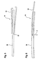
- FIG. 5 the fastening part 14 is shown with the bracket 18 of a wiper arm according to the invention together with a wiper blade 30.
- the wiper blade 30 is in this case designed as a so-called hinge-free wiper blade 30, which has no mounting frame.
- the wiper blade 30 is attached to the base 22 of the U-shaped bracket 18.
- the hinge part 14 is shown with the bracket 18 of the wiper arm and a joint-free wiper blade 30 in a side view.
- this has a reverse keyhole-like opening, so that the wiper blade 30 can be easily clipped into the base 22 of the U-shaped bracket 18.
- the bracket 18 has in this side view beyond a slight bend perpendicular to the plane of movement of the wiper arm 10.
- the joint part 14 is in a working position in which the bracket 18 and thus the struts 20 are biased.
- This working position lies between the first rest position RP1, which in the mounted state is typically located inside the motor vehicle or behind the disc and an axis which results from the extension of the two openings in the fastening part towards the base ( FIG. 2b ).
- the working point AP In the work area AB1 is the working point AP.
- the shorter strut 20 is slightly compressed, or slightly bent, resulting in a bias that pushes the struts 20 in the direction of the rest position RP1. This causes a force on the wiper blade 30 and presses it on the disc.
- the struts 20 and bracket 18 are typically bent from a simple round bar. Of course, other profiles, such as a rectangular steel can be used here. In simpler embodiments, the bracket 18 may also be made of plastic or other material.
- the base 22 of the temple 18 can, as in the Figures 1 and 2 represented, round, ie radius-shaped or level ( FIG. 5 ) be formed. This depends only on the attachment mechanism with which the wiper blade 30 is hinged to the bracket 18.
- the base 22 may be formed as a block in which the struts 20 are individually inserted. The struts 20 are then just not connected to each other as a bracket. Of course, the wiper blade 30 may also be secured elsewhere between the two struts 20. The base 22 is then defined by this attachment point.
- the fastening part 12 is made of plastic or in a metal casting or die casting process.
- the fixing member 12 may also be formed as a stamped and bent part of sheet metal.
Description
Die Erfindung betrifft einen Wischerarm, insbesondere für eine Scheibenwischvorrichtung eines Kraftfahrzeugs nach dem Oberbegriff des unabhängigen Anspruchs.The invention relates to a wiper arm, in particular for a windscreen wiper device of a motor vehicle according to the preamble of the independent claim.
Es sind schon zahlreiche Wischerarme für Scheibenwischvorrichtungen von Kraftfahrzeugen bekannt. Diese umfassen im Wesentlichen ein Befestigungsteil, dass zur Befestigung des Wischerarms an einer Wischerwelle der Scheibenwischvorrichtung dient, sowie ein Gelenkteil, an das ein Wischblatt anlenkbar ist. Im Betrieb der Scheibenwischvorrichtung vermag der Wischerarm in einer Bewegungsebene, die senkrecht zur Drehachse der Wischerwelle angeordnet ist, über die Scheibe des Kraftfahrzeugs zu gleiten. Das Gelenkteil ist im Wesentlichen aus einem u-förmig gebogenen Blechprofil ausgebildet, wobei die Basis des u-förmigen Profils im Wesentlichen parallel zur Bewegungsebene des Wischblatts sowie die Schenkel des u-förmigen Profils senkrecht auf der Bewegungsebene des Wischblattes angeordnet sind. Das Gelenkteil und das Befestigungsteil sind gelenkig miteinander verbunden und zusätzlich durch eine Feder verknüpft. In der Arbeitsposition, wenn das an das freie Ende des Gelenkteils angelenkte Wischblatt auf der Scheibe des Kraftfahrzeugs aufliegt, ist die Feder unter Vorspannung, so dass eine Auflagekraft erzeugt wird, die das Wischblatt auf die Scheibe drückt.There are already numerous wiper arms for windscreen wiper devices of motor vehicles known. These essentially comprise a fastening part, which serves for fastening the wiper arm to a wiper shaft of the windshield wiper device, as well as a joint part, to which a wiper blade can be articulated. During operation of the windscreen wiper device, the wiper arm is able to slide over the window of the motor vehicle in a plane of movement which is perpendicular to the axis of rotation of the wiper shaft. The hinge part is formed substantially from a U-shaped bent sheet metal profile, wherein the base of the U-shaped profile are arranged substantially parallel to the plane of movement of the wiper blade and the legs of the U-shaped profile perpendicular to the plane of movement of the wiper blade. The hinge part and the fastening part are hinged together and additionally linked by a spring. In the working position, when the wiper blade hinged to the free end of the joint part rests on the window of the motor vehicle, the spring is under pretension so that a bearing force is generated which presses the wiper blade onto the window.
Derartige Wischerarme benötigen sehr viele Teile, wie Federn, Gelenkbolzen, Einhängebolzen etc., wodurch hohe Kosten verursacht werden. Darüber hinaus verursachen derartige Wischerarme durch ihr kastenförmiges, umgekehrt u-förmiges Profil einen sehr hohen Luftwiderstand und ihr robustes Aussehen trägt nicht zur Gefälligkeit des Kraftfahrzeugs bei.Such wiper arms require many parts, such as springs, hinge pins, suspension bolts, etc., which causes high costs. Furthermore cause such wiper arms by their box-shaped, inverted U-shaped profile a very high air resistance and their robust appearance does not contribute to the pleasing of the motor vehicle.
Aus der
Der erfindungsgemäße Wischerarm mit den Merkmalen des Hauptanspruchs hat den Vorteil, dass das Gelenkteil im Wesentlichen durch zwei Streben gebildet ist, die jeweils zwei Enden aufweisen, wobei das jeweils eine Ende mit dem Befestigungsteil und das jeweils andere Ende mit dem Wischblatt verbindbar ist. Auf diese Weise ergibt sich ein kostengünstiger Wischerarm, der darüber hinaus nur einen geringen Luftwiderstand aufweist und sehr gefällig im Aussehen ist. Des Weiteren ist die Länge der Streben 20 hierbei so gewählt, dass die eine Streben etwas länger ist als die andere, so dass diese entlang der Längserstreckung des Wischerarms 10 bzw. des Befestigungsteil 12 in unterschiedlichen Stellen in das Befestigungsteil 12 münden. Auf diese Weise entsteht ein Klappmechanismus, da die beiden Streben 20 sich somit auf zwei unterschiedlichen Teilkreisbahnen mit unterschiedlichen Radien bewegen, entstehen dadurch zwei stabile Positionen, in denen sich die Bahnen überschneiden und in denen das Gelenkteil 14 bezüglich dem Befestigungsteil 12 in einer relaxierten Position ist.The wiper arm according to the invention with the features of the main claim has the advantage that the hinge part is essentially formed by two struts, each having two ends, wherein each one end to the fastening part and the other end is connectable to the wiper blade. In this way, results in a cost wiper arm, which also has only a low air resistance and is very pleasing in appearance. Furthermore, the length of the
Durch die in den Unteransprüchen aufgeführten Maßnahmen ergeben sich vorteilhafte Weiterbildungen und Verbesserungen der im Hauptanspruch angegebenen Merkmale.The measures listed in the dependent claims, advantageous refinements and improvements of the main claim features.
Sind die beiden Streben durch Schenkel eines im Wesentlichen u-förmigen Bügels von im Wesentlichen länglicher Gestalt gebildet und das Wischblatt an der Basis des u-förmigen Bügels befestigt, so kann das Gelenkteil besonders kostengünstig aus einer einzigen Metall- oder Kunststoffstange gebogen werden.If the two struts are formed by legs of a substantially U-shaped bracket of substantially elongated shape and the wiper blade attached to the base of the U-shaped bracket, the hinge part can be bent particularly cost-effectively from a single metal or plastic rod.
Besonders vorteilhaft ist, wenn das Gelenkteil in einer zur Bewegungsebene im Wesentlichen senkrechten Klappebene bewegbar ist, da auf diese Weise ein leichter Wechsel des Wischblattes möglich ist.It is particularly advantageous if the joint part is movable in a flap plane substantially perpendicular to the plane of movement, since in this way a slight change of the wiper blade is possible.
Hierbei ist es von besonderem Vorteil, wenn das Gelenkteil durch Übervindung einer federartigen Kraft zwischen mindestens zwei Ruhepositionen klappbar ist. Dadurch kann der Wischerarm von der Scheibe abgehoben werden und verharrt, von der Scheibe abgehoben, in einer Ruheposition, so dass ein noch leichterer Wechsel des Wischblatts gewährleistet ist.It is particularly advantageous if the hinge part can be folded by overcoming a spring-like force between at least two rest positions. Thereby, the wiper arm can be lifted off the disc and remains, lifted off the disc, in a rest position, so that an even easier change of the wiper blade is ensured.
Sind die Streben des Wischerarms derart vorgespannt, dass das Wischblatt in der Arbeitsposition, in der sich der Wischerarm während des Betriebs befindet, auf die Scheibe gedrückt wird, so kann auf separate Federn verzichtet werden.If the struts of the wiper arm are pretensioned such that the wiper blade is pressed onto the window in the working position in which the wiper arm is located during operation, separate springs can be dispensed with.
Besonders einfach kann dies dadurch verwirklicht werden, dass die einen, mit dem Befestigungsteil verbundenen Enden der Streben, bezüglich der Bewegungsebene in verschiedenen Höhen in das Befestigungsteil münden.This can be realized in a particularly simple manner in that the one ends of the struts connected to the fastening part open into the fastening part at different heights with respect to the plane of movement.
Ebenso vorteilhaft ist es, wenn die einen Enden der Streben etwa parallel zur Basis nach Innen gebogen sind und in Öffnungen im Befestigungsteil klammerartig eingreifen.It is equally advantageous if the one ends of the struts are bent inwards approximately parallel to the base and engage in openings in the fastening part in the manner of a clip.
Eine verbesserte Stabilität und Haltbarkeit wird dadurch erzielt, dass die Öffnungen im Befestigungsteil durch Buchsen, insbesondere Stahl- oder Messingbuchsen verstärkt sind.An improved stability and durability is achieved in that the openings in the fastening part are reinforced by bushings, in particular steel or brass bushes.
Insbesondere ist es vorteilhaft wenn das Wischblatt in relaxiertem Zustand senkrecht zur Bewegungsebene eine Biegung aufweist.In particular, it is advantageous if the wiper blade in the relaxed state perpendicular to the plane of movement has a bend.
Ein Ausführungsbeispiel der Erfindung ist in den Zeichnungen dargestellt und in der nachfolgenden Beschreibung näher erläutert. Es zeigen
-
Figur 1 , einen erfindungsgemäßen Wischerarm in einer Draufsicht, -
Figur 2 , einen erfindungsgemäßen Wischerarm in einer Teilschnittdarstellung, -
Figur 2b , eine schematische Zeichnung zur Mechanik eines erfindungsgemäßen Wischerarms, -
Figur 3 , ein Befestigungsteil eines erfindungsgemäßen Wischerarms in einer Teilschnittdarstellung, -
Figur 4 , das Befestigungsteil ausFigur 3 in einer weiteren Teilschnittdarstellung, -
Figur 5 , das Gelenk-teil eines erfindungsgemäßen Wischerarmes mit einem Wischblatt in einer schematischen Draufsicht und -
Figur 6 , ein Gelenkteil eines erfindungsgemäßen Wischerarms mit einem Wischblatt in einer Seitenansicht.
-
FIG. 1 , a wiper arm according to the invention in a plan view, -
FIG. 2 , a wiper arm according to the invention in a partial sectional view, -
FIG. 2b , a schematic drawing of the mechanics of a wiper arm according to the invention, -
FIG. 3 , a fastening part of a wiper arm according to the invention in a partial sectional view, -
FIG. 4 , the mounting partFIG. 3 in a further partial sectional view, -
FIG. 5 , The hinge part of a wiper arm according to the invention with a wiper blade in a schematic plan view and -
FIG. 6 , A hinge part of a wiper arm according to the invention with a wiper blade in a side view.
An dem, dem Loch 16 abgewandten Ende ist das Gelenkteil 14 angelenkt. Das Gelenkteil 14 ist in seiner Längserstreckung durch einen Bügel 18 gebildet, der von im Wesentlichen u-förmiger Gestalt ist. Die beiden Schenkel des u-förmigen Bügels 18 bilden Streben 20, die durch die Basis 22 des u-förmigen Bügels 18 an dem, dem Befestigungsteil 12 abgewandten Ende des Gelenkteils 14 verbunden sind. Zur Verbesserung der Optik und der aerodynamischen Eigenschaften ist im Bereich der Anlenkung zwischen Befestigungsteil 12 und Gelenkteil 14 noch eine Blende 24 angeordnet, die aus Blech oder Kunststoff ausgebildet ist und auf das Befestigungsteil 12 oder das Gelenkteil 14 aufgeklipst, aufgeklebt oder aufgeprägt ist. Selbstverständlich kann die Blende 24 auch in anderer Weise am Befestigungsteil 12 oder an den Streben 20 des Gelenkteils 14 befestigt sein. Im Betrieb pendelt der Wischerarm um das Loch 16 in dem die Wischerwelle befestigt ist. Durch diese Pendelbewegung wird die Bewegungsebene definiert, in der sich der Wischerarm bzw. das an die Basis 22 des Wischerarms angelenkte Wischblatt 30 bewegen.At the end facing away from the
In
In einer Weiterbildung umklammert die Blende 24 die Enden der Streben 20 derart, dass diese aus den Bohrungen 26 nicht entweichen können. Weiterhin wird durch die Blende 24 auch eine Abklappbegrenzung erreicht, die den Abklappwinkel des Bügels 18 gegenüber dem Befestigungsteil 12 begrenzt.In a development, the
Die Streben 20, der
In
In
In
In
Zur Erzeugung einer Auflagekraft F, mit der das Wischblatt 30 auf die Scheibe gedrückt wird, befindet sich das Gelenkteil 14 in einer Arbeitsposition, in der der Bügel 18 und damit die Streben 20 vorgespannt sind. Diese Arbeitsposition liegt zwischen der ersten Ruheposition RP1, die sich im montiertem Zustand typischerweise im Innern des Kraftfahrzeugs, bzw. hinter der Scheibe befindet und einer Achse, die sich aus der Verlängerung der beiden Öffnungen im Befestigungsteil zur Basis hin ergibt (
Die Streben 20 bzw. Bügel 18 sind typischerweise aus einem einfachen Rundstahl gebogen. Selbstverständlich können hier auch andere Profile, wie beispielsweise ein Rechteckstahl verwendet werden. In einfacheren Ausführungsformen kann der Bügel 18 auch aus Kunststoff oder einem anderen Material gefertigt sein. Die Basis 22 des Bügels 18 kann, wie in den
Das Befestigungsteil 12 ist aus Kunststoff oder in einem Metallguss oder Druckgussverfahren hergestellt. Selbstverständlich kann das Befestigungsteil 12 aber auch als Stanzbiegeteil aus Blech ausgebildet sein.The
Claims (9)
- Wiper arm (10), in particular for a windscreen wiper device of a motor vehicle, at least comprising:- a fastening part (12) for fastening to a wiper shaft of the windscreen wiper device,- an articulated part (14) to which a wiper blade (30) can be coupled, said wiper blade being able to slide in a plane of movement over a window of the motor vehicle during the operation of the windscreen wiper device, wherein- the articulated part (14) is substantially formed by two struts (20), both of which have two ends,- one end in each case is connected directly or indirectly to the fastening part (12), and- the other end can be connected directly or indirectly to the wiper blade (30),characterized- in that the length of the struts (20) is selected in such a manner that one strut (20) is somewhat longer than the other, and therefore said struts lead into the fastening part (12) at different points along the longitudinal extent of the wiper arm (10) and of the fastening part (12).
- Wiper arm (10) according to Claim 1, characterized in that the two struts (20) are formed limbs of a substantially U-shaped bow (18) of substantially elongate design, said bow comprising a base (22) and the two limbs, and the wiper blade (30) can be connected directly or indirectly to the base (22).
- Wiper arm (10) according to one of the preceding claims, characterized in that the articulated part (14) can be moved in a folding plane substantially perpendicular to the plane of movement.
- Wiper arm (10) according to Claim 3, characterized in that the articulated part can be folded between at least two inoperative positions (RP1, RP2) by overcoming a spring-like force.
- Wiper arm (10) according to one of the preceding claims, characterized in that, during operation, the wiper arm (10) is in a working position (AP) in which the struts (20) are pre-tensioned in such a manner that the wiper blade (30) is pressed onto the window.
- Wiper arm (10) according to one of Claims 3 to 5, characterized in that the struts (20), at the ends connected to the fastening part (12), lead in particular into the fastening part (12) at different heights with respect to the plane of movement.
- Wiper arm (10) according to one of Claims 3 to 6, characterized in that the struts (20), at one end, are bent inwards approximately parallel to the base (22) and engage in the manner of clips in openings (26) in the fastening part (12).
- Wiper arm (10) according to Claim 7, characterized in that the openings (26) in the fastening part (12) are reinforced by bushes (28).
- Wiper arm (10) according to one of the preceding claims, characterized in that, in the relaxed state, the wiper blade (30) has a bend perpendicular to the plane of movement.
Applications Claiming Priority (2)
| Application Number | Priority Date | Filing Date | Title |
|---|---|---|---|
| DE10345803A DE10345803A1 (en) | 2003-09-30 | 2003-09-30 | Windscreen wiper arm has mounting section with bearing which fits over drive shaft, U-shaped connecting section with two arms fitting on end of this and wiper blade being mounted on its opposite end |
| PCT/DE2004/000700 WO2005042318A1 (en) | 2003-09-30 | 2004-04-03 | Wiper arm, in particular for a windscreen-wiper device of a motor vehicle |
Publications (2)
| Publication Number | Publication Date |
|---|---|
| EP1670666A1 EP1670666A1 (en) | 2006-06-21 |
| EP1670666B1 true EP1670666B1 (en) | 2009-09-23 |
Family
ID=34306202
Family Applications (1)
| Application Number | Title | Priority Date | Filing Date |
|---|---|---|---|
| EP04725603A Expired - Fee Related EP1670666B1 (en) | 2003-09-30 | 2004-04-03 | Wiper arm, in particular for a windscreen-wiper device of a motor vehicle |
Country Status (6)
| Country | Link |
|---|---|
| EP (1) | EP1670666B1 (en) |
| KR (1) | KR101067458B1 (en) |
| CN (1) | CN1816473B (en) |
| DE (2) | DE10345803A1 (en) |
| ES (1) | ES2332786T3 (en) |
| WO (1) | WO2005042318A1 (en) |
Families Citing this family (5)
| Publication number | Priority date | Publication date | Assignee | Title |
|---|---|---|---|---|
| DE102010062992A1 (en) * | 2010-12-14 | 2012-06-14 | Robert Bosch Gmbh | wiper cover |
| DE102014201829A1 (en) * | 2014-02-03 | 2015-08-06 | Robert Bosch Gmbh | Windshield wiper device |
| DE102017208371A1 (en) * | 2017-05-18 | 2018-11-22 | Robert Bosch Gmbh | Wischarmvorrichtung |
| DE102017218126A1 (en) | 2017-10-11 | 2019-04-11 | Robert Bosch Gmbh | Wiper lever, in particular for a disc of a motor vehicle |
| DE102017218128A1 (en) | 2017-10-11 | 2019-04-11 | Robert Bosch Gmbh | Wiper lever, in particular for a disc of a motor vehicle |
Family Cites Families (8)
| Publication number | Priority date | Publication date | Assignee | Title |
|---|---|---|---|---|
| US2043218A (en) * | 1931-11-14 | 1936-06-09 | John W Anderson | Windshield wiper |
| US2094732A (en) * | 1931-11-14 | 1937-10-05 | John W Anderson | Windshield wiper |
| DE2812412A1 (en) * | 1978-03-22 | 1979-09-27 | Rau Swf Autozubehoer | WIPERS, IN PARTICULAR FOR VEHICLES |
| FR2452403A1 (en) * | 1979-03-29 | 1980-10-24 | Morette Jacques | DOUBLE WINDSCREEN WIPER |
| DE10052616A1 (en) * | 2000-10-24 | 2002-05-08 | Bosch Gmbh Robert | wiper arm |
| WO2002040328A1 (en) * | 2000-11-18 | 2002-05-23 | Robert Bosch Gmbh | Device for detachably connecting a wiper blade for cleaning windows of, in particular, motor vehicles to a driven wiper arm |
| DE10227781B4 (en) * | 2002-06-21 | 2013-11-28 | Robert Bosch Gmbh | Windshield wiper device |
| US6813802B2 (en) * | 2002-06-28 | 2004-11-09 | Valeo Electrical Systems, Inc. | Prestressed wiper arm |
-
2003
- 2003-09-30 DE DE10345803A patent/DE10345803A1/en not_active Ceased
-
2004
- 2004-04-03 CN CN2004800186626A patent/CN1816473B/en not_active Expired - Fee Related
- 2004-04-03 KR KR1020057021846A patent/KR101067458B1/en active IP Right Grant
- 2004-04-03 EP EP04725603A patent/EP1670666B1/en not_active Expired - Fee Related
- 2004-04-03 WO PCT/DE2004/000700 patent/WO2005042318A1/en active Application Filing
- 2004-04-03 ES ES04725603T patent/ES2332786T3/en not_active Expired - Lifetime
- 2004-04-03 DE DE502004010127T patent/DE502004010127D1/en not_active Expired - Lifetime
Also Published As
| Publication number | Publication date |
|---|---|
| WO2005042318A1 (en) | 2005-05-12 |
| DE10345803A1 (en) | 2005-04-14 |
| KR20060064563A (en) | 2006-06-13 |
| KR101067458B1 (en) | 2011-09-27 |
| ES2332786T3 (en) | 2010-02-12 |
| DE502004010127D1 (en) | 2009-11-05 |
| EP1670666A1 (en) | 2006-06-21 |
| CN1816473B (en) | 2011-06-15 |
| CN1816473A (en) | 2006-08-09 |
Similar Documents
| Publication | Publication Date | Title |
|---|---|---|
| EP1833707B1 (en) | Windscreen wiper system | |
| EP1098796B1 (en) | Wiper device for motor vehicle windows | |
| EP1332075B1 (en) | Device for detachably and hingedly connecting a wiper blade for cleaning panes to a wiper arm | |
| DE10227781B4 (en) | Windshield wiper device | |
| EP1461235B1 (en) | Windscreen wiper comprising a wiper arm | |
| EP1519862B1 (en) | Wiper blade | |
| EP1501710B1 (en) | Wiper blade | |
| EP1363816B1 (en) | Wiper arm with a pivoting connected wiper blade | |
| DE102005048344A1 (en) | wiper arm | |
| DE102008000933A1 (en) | Device for articulating a wiper blade with a wiper arm | |
| EP0923468B1 (en) | Device for linking a wiper blade to a wiper arm | |
| DE19951440A1 (en) | Wiper arm for a vehicle | |
| EP1670666B1 (en) | Wiper arm, in particular for a windscreen-wiper device of a motor vehicle | |
| EP1720749B1 (en) | Wiper arm for a window wiping device | |
| EP1575813B1 (en) | Wiper crank with a wiper arm and a wiper blade | |
| DE102005046653A1 (en) | Windscreen wiper device, in particular for a motor vehicle | |
| DE10052616A1 (en) | wiper arm | |
| DE102015221910A1 (en) | Wischarmvorrichtung | |
| DE19811859B4 (en) | wiper device | |
| EP1727716B1 (en) | Wiper arm for a windscreen wiping device | |
| DE10118010B4 (en) | Exterior rearview mirror with swivel-mounted mirror head | |
| DE102013226351A1 (en) | Wiper arm and wiper device | |
| EP1462328B1 (en) | Wiper arm articulation device | |
| DE102007061377A1 (en) | Windscreen wiper arm, particularly for motor vehicle, has mounting part connected with wiper shaft and carrier part that is carrier of wiper blade | |
| EP1606150A1 (en) | Articulated arm with a wiper rod |
Legal Events
| Date | Code | Title | Description |
|---|---|---|---|
| PUAI | Public reference made under article 153(3) epc to a published international application that has entered the european phase |
Free format text: ORIGINAL CODE: 0009012 |
|
| 17P | Request for examination filed |
Effective date: 20060502 |
|
| AK | Designated contracting states |
Kind code of ref document: A1 Designated state(s): DE ES FR GB |
|
| DAX | Request for extension of the european patent (deleted) | ||
| RBV | Designated contracting states (corrected) |
Designated state(s): DE ES FR GB |
|
| 17Q | First examination report despatched |
Effective date: 20081120 |
|
| GRAP | Despatch of communication of intention to grant a patent |
Free format text: ORIGINAL CODE: EPIDOSNIGR1 |
|
| GRAS | Grant fee paid |
Free format text: ORIGINAL CODE: EPIDOSNIGR3 |
|
| GRAA | (expected) grant |
Free format text: ORIGINAL CODE: 0009210 |
|
| AK | Designated contracting states |
Kind code of ref document: B1 Designated state(s): DE ES FR GB |
|
| REG | Reference to a national code |
Ref country code: GB Ref legal event code: FG4D Free format text: NOT ENGLISH |
|
| REF | Corresponds to: |
Ref document number: 502004010127 Country of ref document: DE Date of ref document: 20091105 Kind code of ref document: P |
|
| REG | Reference to a national code |
Ref country code: ES Ref legal event code: FG2A Ref document number: 2332786 Country of ref document: ES Kind code of ref document: T3 |
|
| PLBE | No opposition filed within time limit |
Free format text: ORIGINAL CODE: 0009261 |
|
| STAA | Information on the status of an ep patent application or granted ep patent |
Free format text: STATUS: NO OPPOSITION FILED WITHIN TIME LIMIT |
|
| 26N | No opposition filed |
Effective date: 20100624 |
|
| REG | Reference to a national code |
Ref country code: FR Ref legal event code: PLFP Year of fee payment: 13 |
|
| REG | Reference to a national code |
Ref country code: FR Ref legal event code: PLFP Year of fee payment: 14 |
|
| REG | Reference to a national code |
Ref country code: FR Ref legal event code: PLFP Year of fee payment: 15 |
|
| PGFP | Annual fee paid to national office [announced via postgrant information from national office to epo] |
Ref country code: DE Payment date: 20190627 Year of fee payment: 16 |
|
| PGFP | Annual fee paid to national office [announced via postgrant information from national office to epo] |
Ref country code: FR Payment date: 20200421 Year of fee payment: 17 Ref country code: ES Payment date: 20200516 Year of fee payment: 17 |
|
| PGFP | Annual fee paid to national office [announced via postgrant information from national office to epo] |
Ref country code: GB Payment date: 20200423 Year of fee payment: 17 |
|
| REG | Reference to a national code |
Ref country code: DE Ref legal event code: R119 Ref document number: 502004010127 Country of ref document: DE |
|
| PG25 | Lapsed in a contracting state [announced via postgrant information from national office to epo] |
Ref country code: DE Free format text: LAPSE BECAUSE OF NON-PAYMENT OF DUE FEES Effective date: 20201103 |
|
| GBPC | Gb: european patent ceased through non-payment of renewal fee |
Effective date: 20210403 |
|
| PG25 | Lapsed in a contracting state [announced via postgrant information from national office to epo] |
Ref country code: GB Free format text: LAPSE BECAUSE OF NON-PAYMENT OF DUE FEES Effective date: 20210403 Ref country code: FR Free format text: LAPSE BECAUSE OF NON-PAYMENT OF DUE FEES Effective date: 20210430 |
|
| REG | Reference to a national code |
Ref country code: ES Ref legal event code: FD2A Effective date: 20220629 |
|
| PG25 | Lapsed in a contracting state [announced via postgrant information from national office to epo] |
Ref country code: ES Free format text: LAPSE BECAUSE OF NON-PAYMENT OF DUE FEES Effective date: 20210404 |