EP1519862B1 - Wiper blade - Google Patents
Wiper blade Download PDFInfo
- Publication number
- EP1519862B1 EP1519862B1 EP03761402A EP03761402A EP1519862B1 EP 1519862 B1 EP1519862 B1 EP 1519862B1 EP 03761402 A EP03761402 A EP 03761402A EP 03761402 A EP03761402 A EP 03761402A EP 1519862 B1 EP1519862 B1 EP 1519862B1
- Authority
- EP
- European Patent Office
- Prior art keywords
- wiper
- wiper blade
- pivot pin
- cap
- rod
- Prior art date
- Legal status (The legal status is an assumption and is not a legal conclusion. Google has not performed a legal analysis and makes no representation as to the accuracy of the status listed.)
- Expired - Lifetime
Links
- 210000000078 claw Anatomy 0.000 claims description 22
- 239000002184 metal Substances 0.000 claims description 22
- 230000002349 favourable effect Effects 0.000 description 3
- 238000003860 storage Methods 0.000 description 3
- 238000000034 method Methods 0.000 description 2
- 239000004033 plastic Substances 0.000 description 2
- 229910000639 Spring steel Inorganic materials 0.000 description 1
- 238000005452 bending Methods 0.000 description 1
- 238000013016 damping Methods 0.000 description 1
- 238000009826 distribution Methods 0.000 description 1
- 230000000694 effects Effects 0.000 description 1
- 230000005489 elastic deformation Effects 0.000 description 1
- 239000004744 fabric Substances 0.000 description 1
- 238000009434 installation Methods 0.000 description 1
- 238000003825 pressing Methods 0.000 description 1
- 238000011144 upstream manufacturing Methods 0.000 description 1
- 230000000007 visual effect Effects 0.000 description 1
- 238000003466 welding Methods 0.000 description 1
Images


Classifications
-
- B—PERFORMING OPERATIONS; TRANSPORTING
- B60—VEHICLES IN GENERAL
- B60S—SERVICING, CLEANING, REPAIRING, SUPPORTING, LIFTING, OR MANOEUVRING OF VEHICLES, NOT OTHERWISE PROVIDED FOR
- B60S1/00—Cleaning of vehicles
- B60S1/02—Cleaning windscreens, windows or optical devices
- B60S1/04—Wipers or the like, e.g. scrapers
- B60S1/32—Wipers or the like, e.g. scrapers characterised by constructional features of wiper blade arms or blades
- B60S1/40—Connections between blades and arms
- B60S1/4067—Connections between blades and arms for arms provided with a side pin
-
- B—PERFORMING OPERATIONS; TRANSPORTING
- B60—VEHICLES IN GENERAL
- B60S—SERVICING, CLEANING, REPAIRING, SUPPORTING, LIFTING, OR MANOEUVRING OF VEHICLES, NOT OTHERWISE PROVIDED FOR
- B60S1/00—Cleaning of vehicles
- B60S1/02—Cleaning windscreens, windows or optical devices
- B60S1/04—Wipers or the like, e.g. scrapers
- B60S1/32—Wipers or the like, e.g. scrapers characterised by constructional features of wiper blade arms or blades
- B60S1/38—Wiper blades
- B60S1/3848—Flat-type wiper blade, i.e. without harness
- B60S1/3849—Connectors therefor; Connection to wiper arm; Attached to blade
- B60S1/3851—Mounting of connector to blade assembly
- B60S1/3856—Gripping the blade
-
- B—PERFORMING OPERATIONS; TRANSPORTING
- B60—VEHICLES IN GENERAL
- B60S—SERVICING, CLEANING, REPAIRING, SUPPORTING, LIFTING, OR MANOEUVRING OF VEHICLES, NOT OTHERWISE PROVIDED FOR
- B60S1/00—Cleaning of vehicles
- B60S1/02—Cleaning windscreens, windows or optical devices
- B60S1/04—Wipers or the like, e.g. scrapers
- B60S1/32—Wipers or the like, e.g. scrapers characterised by constructional features of wiper blade arms or blades
- B60S1/40—Connections between blades and arms
- B60S1/4083—Connections between blades and arms for arms provided with a flat end
-
- B—PERFORMING OPERATIONS; TRANSPORTING
- B60—VEHICLES IN GENERAL
- B60S—SERVICING, CLEANING, REPAIRING, SUPPORTING, LIFTING, OR MANOEUVRING OF VEHICLES, NOT OTHERWISE PROVIDED FOR
- B60S1/00—Cleaning of vehicles
- B60S1/02—Cleaning windscreens, windows or optical devices
- B60S1/04—Wipers or the like, e.g. scrapers
- B60S1/32—Wipers or the like, e.g. scrapers characterised by constructional features of wiper blade arms or blades
- B60S1/38—Wiper blades
- B60S1/3806—Means, or measures taken, for influencing the aerodynamic quality of the wiper blades
-
- B—PERFORMING OPERATIONS; TRANSPORTING
- B60—VEHICLES IN GENERAL
- B60S—SERVICING, CLEANING, REPAIRING, SUPPORTING, LIFTING, OR MANOEUVRING OF VEHICLES, NOT OTHERWISE PROVIDED FOR
- B60S1/00—Cleaning of vehicles
- B60S1/02—Cleaning windscreens, windows or optical devices
- B60S1/04—Wipers or the like, e.g. scrapers
- B60S1/32—Wipers or the like, e.g. scrapers characterised by constructional features of wiper blade arms or blades
- B60S1/40—Connections between blades and arms
- B60S1/4067—Connections between blades and arms for arms provided with a side pin
- B60S1/4074—Connections between blades and arms for arms provided with a side pin with means provided on the blade for locking the side pin
Definitions
- the invention is based on a wiper blade according to the preamble of claim 1.
- wipers have a wiper arm, which sits on a wiper shaft. This is driven by a wiper motor.
- a wiper blade is hinged to the free end of the wiper arm. It usually has a Hatgliediges mounting bracket system with a center bracket. At this subordinate bracket are hinged, of which at least some hold with claws at their ends a wiper strip.
- jointless wiper blades which have a perpendicular to the vehicle window resilient, elastic support member, which is made of plastic instead of the support bracket system. To improve the spring characteristic, it may have at least one spring rail of spring steel. The support member has a stronger curvature in the unloaded state than the vehicle window, so that the wiper strip under the contact force of the wiper arm with a suitable pressure distribution to the vehicle window applies.
- a windshield wiper with a jointless wiper blade is known, which is hingedly connected to a wiper arm via a so-called "sidelock system".
- a two-part connector whose first part has a block-shaped portion with a bearing bore and which includes integrally formed form-locking elements serving as a support element spring strips laterally and from below.
- the second part is fixed to the free end of the wiper arm, which has a vehicle window towards the open, U-shaped profile.
- a pin is laterally and transversely to the longitudinal direction of the wiper arm and pointing to the wiper blade inserted into the second part and pivotally mounted in the bearing bore of the first part of the connecting piece.
- a bridge is arranged offset in the longitudinal direction of the second part of the connector, which is angled at its free end to the side of the pin out.
- the pin In a mounting position, in which the wiper blade is held transversely to the longitudinal direction of the wiper arm, the pin can be pushed into the bearing bore of the connecting part. If the wiper blade is then rotated parallel to the longitudinal direction of the wiper arm, the bridge engages over the wiper blade and locks it with its angled end, so that lateral guide surfaces of the block-shaped portion of the first part of the connector in the assembled state between the angled Are stirred at the end of the bridge and an opposite surface of the second part.
- the bridge dips in the operating position of the wiper blade in a corresponding groove of the first part and includes approximately flush with the top of it.
- the wiper blade For disassembly, the wiper blade must be swung in the opposite direction until the angled end is disengaged and the wiper blade can be pulled from the pin.
- a wiper device for windows of motor vehicles has a wiper blade to which a pivot pin is firmly connected.
- the pivot pin extends in a plane that is substantially parallel to the vehicle window, and is rotatably mounted in a bearing bore of the wiper arm. So that the pivot pin does not slide out of the bearing bore during a wiping movement, the wiper blade is locked in the axial direction of the pivot pin with respect to the wiper arm by an extension of the wiper arm projecting projection engages in a groove of a projection which is fixedly connected laterally by the wiper blade with this. The outer edge of the groove forms a shoulder against which the projection rests in the operating position and thus locks the wiper blade axially to the pivot pin.
- the joint comprises a cap, which covers the connecting part and is secured thereto.
- the cap secures the wiper blade and the Wiper rod in the mounted position.
- This achieves a very flat connection between a preferably jointless wiper blade and a wiper rod, wherein the connecting parts for left-hand drive vehicles and right-hand drive vehicles are the same. Only the wiper rod is mirror-inverted.
- the design according to the invention allows numerous variants with free spaces for design design, so that the wiper blade can be adapted to numerous vehicle types. Since most functions for adapting the windshield wiper to a motor vehicle are concentrated on the connecting part and the joint axle, the wiper rod can be kept simple.
- the cap has on its side to the wiper rod towards a bag which is open to the vehicle window and in the longitudinal direction of the wiper rod to this and laterally engages over.
- the pocket can be arranged in extension of the wiper rod, so that an extension of the wiper rod beyond the hinge axis engages in the operating position in the pocket of the cap.
- the pocket can also be arranged in front of the hinge axis, as viewed in the longitudinal direction, from the drive side of the wiper rod, wherein it comprises the wiper rod on the drive side to the hinge axis. This can make the cap and the wiper rod shorter.
- the wiper blade is pivoted by about 90 ° to the wiper rod, the extension of the wiper rod or the wiper rod itself leaves the pocket and the wiper blade can be removed from the joint axis attached to the wiper rod.
- the assembly takes place in the reverse direction.
- the cap may have a guide pin which is guided in a fork at the end of the wiper rod.
- a spoiler is usually placed on the support element on both sides of the connecting part.
- the cap connects the two parts of the spoiler harmoniously, by connecting with connecting sections to the parts, so that there is essentially a continuous spoiler with good flow conditions for the wind.
- the wiper rod has a flat, rectangular cross-sectional profile whose long side extends approximately parallel to the vehicle window, it supports the function of the spoiler, if it is arranged on the upstream side.
- the connecting part in the form of a sheet metal claw, can be made of metal or plastic. It has a parallel to the support element extending back, on the longitudinal sides for ease of installation locking lugs are formed so that it can be mecanicklippst across the support element.
- the connecting part has two side cheeks. They have receiving openings for the hinge axis and are interconnected by a bearing tube when the hinge axis is rotatably mounted in the connecting part.
- the side cheeks have for easy mounting of the cap locking recesses or detent holes, engage in the locking lugs of the cap.
- the cap can be held by a clip that includes the bearing tube.
- the cap can be secured by projecting a free end of the hinge axle over the side wall and engaging a recess in the side wall of the cap.
- the wiper rod can extend above the joint axis, in the same plane as the joint axis or below the joint axis.
- the end projecting beyond the hinge axis is angled or bevelled to the rubber profile of the wiper blade, so that the cap can be made lower with its pocket.
- the wiper rod can be straight. It produces particularly favorable inflow conditions, since it extends the lower side of the spoiler profile and has only a small distance to the vehicle window.
- the articulated axle is rotatably mounted in the connecting part, it is firmly connected to the wiper rod at an end protruding from the connecting part. This can be done by fabric closure, z. B. by welding, by form or adhesion, z. B. by riveting, pressing or the like. Take place.
- the hinge axis at its end, which is associated with the wiper rod, a flat head, are provided in the rivet holes for rivets.
- the wiper rod has corresponding rivet holes and is riveted to the hinge axis.
- the hinge axis has a flat head, on which a transversely to the hinge axis projecting polygon, z. B. a three, four or hexagon is formed, which is pressed into a corresponding opening of the wiper rod and secured at its protruding end by wobble rivets.
- Tumbling riveting is a riveting method in which the riveting tool rollovers during riveting. Before assembly, the wiper rods and heads of the joint axles are painted black.
- the hinge axis has a head with a slot for receiving the flat wiper rod, which is secured by a transverse pin or a rivet in the slot.
- the wiper rod in the region of the hinge axis may have a hub, which comprises the hinge axis and is secured by a transverse pin on this.
- the flat wiper rod is twisted at its end by about 90 °, so that a broad side of one end is transverse to the hinge axis.
- the end has a receiving bore for a hinge axis with a collar, which is followed by a knurled seat, on which the receiving bore is pressed and is secured by a caulked disc.
- the projecting beyond the hinge axis end is bevelled towards the rubber profile of the wiper blade and engages in an associated pocket of the cap.
- This version has a short length of the joint axis. Nevertheless, the favorable position of the wiper rod to the spoiler remains in the majority of the wiper rod.
- a hingeless wiper blade 20 has a rubber profile 22 which is secured to a flat support member 24. This usually consists of one or two spring strips, which are embedded in the upper part of the rubber profile 22.
- a joint 30 is provided in the central region of the wiper blade 20. This has as a connecting part a metal claw 32, the back 34 spans the support member 24 and is secured with locking lugs 36 thereto.
- the locking lugs 36 can be pushed over the support element 24 in the longitudinal direction or be formed as a clip connection and be clipped by elastic deformation transverse to the support member 24.
- the locking lugs 36 which are provided laterally at the ends of the sheet metal claw 32, are on the longitudinal sides 66 of the sheet metal claw 32 side walls 38 away from the rubber profile 22 from. They hold a bearing tube 40 which extends transversely to the wiper blade 20 and approximately parallel to a vehicle window, not shown. In the bearing tube 40, a hinge axis 42 is inserted, which protrudes on one side to the wiper rod 28 with a head 44 from the bearing tube 40.
- the wiper rod 28 has a rectangular cross-section, wherein the longer sides extend approximately parallel to the hinge axis 42. In the embodiments according to FIGS. 1 to 3, the wiper rod 28 engages in a slot 46 of the head 44 of the articulation axis 42 and is secured by a transverse pin 48. The wiper rod 28 projects beyond the slot 46 with a finger 52. The finger 52 is narrower than the wiper rod 28 and lies on the wiper blade 20 facing side of the wiper rod 28th
- the sheet metal claw 32 is covered by a cap 54 which connects with connection profiles 64 harmoniously to the parts of the spoiler 26.
- the cap 54 is releasably secured to the sheet metal claw 32.
- it has on the inside of its side walls 60 latching lugs 56 which engage in corresponding openings 104 (FIG. 11) or depressions of the sheet metal claw 32.
- it has in its central region a clip 58 for mounting on the bearing tube 40.
- the hinge axis 42 protrudes with its end facing away from the head 44 (FIG. 2) beyond the side wall 38, said end in a recess of the Side wall 60 of the cap 54 engages (Fig. 3) and thus supports their support on the sheet metal claw 32.
- the cap 54 has on the side of the wiper rod 28 a pocket 62 (FIG. 3) which is open toward the vehicle window and into which the finger 52 of the wiper rod 28 engages in the operating position in which the wiper blade 20 bears against the vehicle window.
- An outer wall 68 of the pocket 62 prevents the wiper rod 28 from moving outwardly with its finger 52, so that the hinge axle 42 is locked in the axial direction.
- the pocket 62 is largely covered by a cover 50 which sits on the hinge axis 42 and harmoniously connects to the contour of the wiper rod 28 and the cap 54.
- the cover 50 is simultaneously an impact protection or
- Damping element It prevents damage to the vehicle window if the wiper arm accidentally strikes the vehicle window when the wiper blade is changed.
- FIGS. 4 to 6 show wiper rods 70, 80, which are connected by welds 74 to one end of the hinge axis 42.
- the wiper rod 70 according to FIG. 4 extends above the articulation axis 42 and projects beyond the articulation axis 42 with an end 72 angled towards the rubber profile 22.
- the angled end 72 engages in the operating position of the wiper blade 20 shown in a pocket 76 of the cap 54, wherein the wiper arm 70 facing edge 78 of the cap 54 extends so that the wiper blade 20 in a direction of arrow rotated by approximately 90 ° position can be easily removed from the hinge axis 42.
- the wiper blade 20 is also mounted by being placed on the hinge axis 42 and then pivoted in the opposite direction.
- the wiper blades 20 according to FIGS. 1, 5 to 7, 10 and 11 are assembled and disassembled.
- the pocket 76 can be made flat, which reduces the wind resistance and improves the visual impression.
- a similar effect is achieved when the wiper rod 80 in the embodiments according to FIGS. 5 and 6 extends below the articulation axis 42 and engages with its straight end 82 extended beyond the articulation axis 42 into a pocket 84 of the cap 54.
- the edge 86 of the pocket 84 is formed so that in the pivoted mounting position assembly or disassembly is easily possible. While in the embodiments of FIGS. 4 and 5, the wiper blade 20 at the assembly must be rotated by about 90 °, the wiper blade 20 can be mounted and dismantled in the embodiment of FIG. 6 already at a smaller tilt angle. This is achieved in that the edge 88 of the pocket 84 extends at a smaller angle to the longitudinal direction of the wiper blade 20.
- the embodiment according to FIG. 7 enables a very narrow joint 30 in that the wiper rod 90 is set at its end 92 in the longitudinal direction by approximately 90 ° so that the longer sides of its rectangular profile run transversely to it in the area of the hinge axis 96.
- the protruding beyond the hinge axis 96 has a bevel end 94 which is inclined towards the rubber profile 22 and engages with the bevel 94 in a pocket 122 of the cap 54.
- the hinge axis 96 (FIG. 9) has a knurled seat 100, onto which the wiper rod 90 is pressed with a receiving opening up to a collar 98 and secured by a disc 102.
- the end of the wiper rods 118 protruding beyond the articulation axis 42 is designed as a fork 112, which in the illustrated operating position comprises a guide pin 116 of the cap 114.
- the fork 112 extends inclined towards the rubber profile 22.
- the wiper rod 118 according to FIG. 16 is inserted in a slot 46 of the head 44 of the articulated axle 42 and secured by a transverse pin 48
- the wiper rod 118 according to FIG. 11 has a hub 120, FIG. which sits on the free end of the hinge axis 42 and is secured by a transverse pin 48.
- the wiper rod 118 can also be welded to the hinge axis 42 like the wiper rods of the previously described embodiments.
- FIGS. 12 to 15 and 18 are similar to the embodiments according to FIGS. 5 and 6.
- the wiper rods 80 and 136 extend underneath the articulation axes 42 and 106 and 138.
- hinge axis 138 of FIGS. 14 and 15 has a flat head 140 with two rivet holes 142 connected by rivets 144 to wiper bar 136 (FIG. 15).
- the hinge axis 106 ( Figure 17) has a flat head 108 on which a square 110 is molded, which is press-fitted into a corresponding opening of the wiper rod 136 and optionally riveted in a tumbling process (Figure 18).
- the caps 54 for the embodiments according to FIGS. 12 to 15 and 18 have on the side to the wiper rod 80, 136 pockets 126, which comprise the wiper rod 80, 136 on their drive side in front of the hinge axis 42, 106, 138, then that the wiper rod 80, 136 does not have to protrude beyond the hinge axis 42, 106, 138.
- very flat wiper blades 20 can be achieved, wherein the cap 54 can be made very flat and closed.
- the hinge axis 178 (Fig. 20, 21) to the wiper rod 28, 90 towards two diametrically arranged wings 180, 182, which extend radially to the hinge axis 28, 90 and in the longitudinal direction of the associated wiper rod 28, 90.
- the hinge axis 178 of Figure 20 like the hinge axis 42 of Figure 1, has a slot 46 in a head 44 into which the wiper rod 28 is inserted and connected by a transverse pin, e.g. a rivet, is secured.
- the propeller shaft 178 according to FIG. 21 has a rivet pin 178 at the end, with which it is fastened to the wiper rod 90, which, like the wiper rod 90 according to FIG. 8, is rotated in the longitudinal direction by 90 °.
- the wings 180, 182 engage in the mounted position of the wiper blade 20 in correspondingly aligned pockets 184, 186 of a pocket 190 (FIG. 19) in the manner of a bayonet closure.
- the bayonet lock for disassembly can be solved or closed during assembly.
- the hinge axis 42, 96, 106, 138 rotatably mounted in the bearing tube 40 of the sheet metal claw 32 and connected to the wiper rod 20, 70, 80, 90, 118, 136
- the hinge axis 146, 164 rotatably with the metal claw 32 and rotatably connected to the wiper rod 150, for example by having a non-circular cross-sectional profile in the form of a polygon or flattened cylinder in corresponding openings of the side walls 38 is held.
- the articulation axis 146 has a semicircular cross-sectional profile with a flattening 148 which points to the rubber profile 22.
- a bearing sleeve 154 which has a cylindrical portion 156 at its outer periphery and the rubber profile 22 through a flattened portion 158 may have.
- a correspondingly bent end 152 of the wiper rod 150 is rotatably mounted (FIG. 23).
- the bent end 152 may also be mounted directly on a round or semi-circular profiled part of the propeller shaft 146, 164.
- the bearing sleeve 154 and the end 152 of the wiper rod 150 are guided in a bearing pocket 162 of a cap 160.
- the cap 160 is fastened by means of latching lugs 56 and a clip 58 on the sheet metal claw 32 and on the hinge axis 146.
- the hinge axis 146 protrudes beyond the bearing sleeve 154 and engages in a recess 176 of the cap 160.
- the wiper blade 20 can be mounted on the wiper rod 150 by turning it with the mounted cap 160 so far that the bent end 152 between the cap 160 and bearing sleeve 154 can be threaded.
- the variant according to FIG. 24 has a hinge axis 164 with a fastening region 166, which has a substantially rectangular cross section and a longitudinal section 168 extending transversely to the longer sides.
- the longer sides of the cross-sectional profile run approximately parallel to the support member 24.
- locking lugs 170 are provided at the ends of the mounting portion, through an opening in the associated side wall 38 protrude and lock with the edge of this opening.
- the hinge axis 164 on a storage area 172 which is bounded by two collars 174 in the axial direction.
- the bent end 152 of the wiper rod 150 is supported and secured by the bearing pocket 152 of the cap 160 in the mounted position.
Landscapes
- Engineering & Computer Science (AREA)
- Mechanical Engineering (AREA)
- Pivots And Pivotal Connections (AREA)
- Cleaning Implements For Floors, Carpets, Furniture, Walls, And The Like (AREA)
Description
Die Erfindung geht von einem Wischblatt nach dem Oberbegriff des Anspruchs 1 aus.The invention is based on a wiper blade according to the preamble of claim 1.
Bekannte Scheibenwischer weisen einen Wischarm auf, der auf einer Wischerwelle sitzt. Diese wird von einem Wischermotor angetrieben. Mit dem freien Ende des Wischarms ist ein Wischblatt gelenkig verbunden. Es besitzt in der Regel ein mehrgliederiges Tragbügelsystem mit einem Mittelbügel. An diesem sind untergeordnete Bügel angelenkt, von denen zumindest einige mit Krallen an ihren Enden eine Wischleiste halten. Es sind auch gelenklose Wischblätter bekannt, die anstelle des Tragbügelsystems ein senkrecht zur Fahrzeugscheibe federndes, elastisches Tragelement besitzen, das aus Kunststoff hergestellt ist. Um die Federeigenschaft zu verbessern, kann es mindestens eine Federschiene aus Federstahl aufweisen. Das Tragelement besitzt im unbelasteten Zustand eine stärkere Krümmung als die Fahrzeugscheibe, so dass sich die Wischleiste unter der Anpresskraft des Wischarms mit einer geeigneten Druckverteilung an die Fahrzeugscheibe anlegt.Known wipers have a wiper arm, which sits on a wiper shaft. This is driven by a wiper motor. A wiper blade is hinged to the free end of the wiper arm. It usually has a mehrgliediges mounting bracket system with a center bracket. At this subordinate bracket are hinged, of which at least some hold with claws at their ends a wiper strip. There are also known jointless wiper blades, which have a perpendicular to the vehicle window resilient, elastic support member, which is made of plastic instead of the support bracket system. To improve the spring characteristic, it may have at least one spring rail of spring steel. The support member has a stronger curvature in the unloaded state than the vehicle window, so that the wiper strip under the contact force of the wiper arm with a suitable pressure distribution to the vehicle window applies.
Gelenklose Wischblätter bauen sehr niedrig, was bezüglich ihres strömungstechnischen Verhaltens und der Geräuschentwicklung im Fahrtwind sehr günstig ist. Aus der DE 199 24 662 A1 ist ein Scheibenwischer mit einem gelenklosen Wischblatt bekannt, das über ein so genanntes "Sidelock-System" mit einem Wischarm gelenkig verbunden ist. Hierzu dient ein zweiteiliges Verbindungsstück, dessen erstes Teil einen blockförmigen Abschnitt mit einer Lagerbohrung aufweist und das mit angeformten Formschlusselementen die als Tragelement dienenden Federleisten seitlich und von unten umfasst. Das zweite Teil ist an dem freien Ende des Wischarms befestigt, der ein zur Fahrzeugscheibe hin offenes, u-förmiges Profil aufweist. Ein Stift ist seitlich und quer zur Längsrichtung des Wischarms und zu dem Wischblatt zeigend in das zweite Teil eingesetzt und in der Lagerbohrung des ersten Teils des Verbindungsstücks schwenkbar gelagert.Artless wiper blades build very low, which is very favorable in terms of their fluidic behavior and the noise in the wind. From DE 199 24 662 A1, a windshield wiper with a jointless wiper blade is known, which is hingedly connected to a wiper arm via a so-called "sidelock system". For this purpose, a two-part connector, whose first part has a block-shaped portion with a bearing bore and which includes integrally formed form-locking elements serving as a support element spring strips laterally and from below. The second part is fixed to the free end of the wiper arm, which has a vehicle window towards the open, U-shaped profile. A pin is laterally and transversely to the longitudinal direction of the wiper arm and pointing to the wiper blade inserted into the second part and pivotally mounted in the bearing bore of the first part of the connecting piece.
Parallel zum Stift ist am zweiten Teil des Verbindungsstücks in Längsrichtung versetzt eine Brücke angeordnet, die an ihrem freien Ende zur Seite des Stifts hin abgewinkelt ist. In einer Montageposition, in der das Wischblatt quer zur Längsrichtung des Wischarms gehalten wird, kann der Stift in die Lagerbohrung des Verbindungsteils geschoben werden. Wird das Wischblatt anschließend parallel zur Längsrichtung des Wischarms gedreht, übergreift die Brücke das Wischblatt und verriegelt es mit ihrem abgewinkelten Ende, so dass seitliche Führungsflächen des blockförmigen Abschnitts des ersten Teils des Verbindungsstücks im montierten Zustand zwischen dem abgewinkelten Ende der Brücke und einer gegenüberliegenden Fläche des zweiten Teils gerührt sind. Die Brücke taucht in der Betriebsstellung des Wischblatts in eine entsprechende Nut des ersten Teils ein und schließt etwa bündig mit dessen Oberseite ab. Zur Demontage muss das Wischblatt in die entgegengesetzte Richtung geschwenkt werden, bis das abgewinkelte Ende außer Eingriff gebracht ist und das Wischblatt vom Stift gezogen werden kann.Parallel to the pin, a bridge is arranged offset in the longitudinal direction of the second part of the connector, which is angled at its free end to the side of the pin out. In a mounting position, in which the wiper blade is held transversely to the longitudinal direction of the wiper arm, the pin can be pushed into the bearing bore of the connecting part. If the wiper blade is then rotated parallel to the longitudinal direction of the wiper arm, the bridge engages over the wiper blade and locks it with its angled end, so that lateral guide surfaces of the block-shaped portion of the first part of the connector in the assembled state between the angled Are stirred at the end of the bridge and an opposite surface of the second part. The bridge dips in the operating position of the wiper blade in a corresponding groove of the first part and includes approximately flush with the top of it. For disassembly, the wiper blade must be swung in the opposite direction until the angled end is disengaged and the wiper blade can be pulled from the pin.
Aus der DE 28 30 508 A 1 ist eine Wischvorrichtung für Scheiben von Kraftfahrzeugen bekannt. Diese besitzt ein Wischblatt, mit dem ein Gelenkzapfen fest verbunden ist. Der Gelenkzapfen erstreckt sich in einer Ebene, die im Wesentlichen parallel zu der Fahrzeugscheibe verläuft, und ist in einer Lagerbohrung des Wischarms drehbar gelagert. Damit der Gelenkzapfen während einer Wischbewegung nicht aus der Lagerbohrung gleitet, ist das Wischblatt in axialer Richtung des Gelenkzapfens gegenüber dem Wischarm verriegelt, indem ein in Verlängerung des Wischarms vorspringender Ansatz in eine Nut eines Vorsprungs eingreift, der seitlich vom Wischblatt mit diesem fest verbunden ist. Die äußere Flanke der Nut bildet eine Schulter, an der der Vorsprung in der Betriebsstellung anliegt und somit das Wischblatt axial zum Gelenkzapfen verriegelt.From DE 28 30 508 A 1 a wiper device for windows of motor vehicles is known. This has a wiper blade to which a pivot pin is firmly connected. The pivot pin extends in a plane that is substantially parallel to the vehicle window, and is rotatably mounted in a bearing bore of the wiper arm. So that the pivot pin does not slide out of the bearing bore during a wiping movement, the wiper blade is locked in the axial direction of the pivot pin with respect to the wiper arm by an extension of the wiper arm projecting projection engages in a groove of a projection which is fixedly connected laterally by the wiper blade with this. The outer edge of the groove forms a shoulder against which the projection rests in the operating position and thus locks the wiper blade axially to the pivot pin.
Weiterhin ist aus der DE-A-4413661 ein Wischblatt mit den Merkmalen des Oberbegriffs des Anspruchs 1 bekannt.Furthermore, from DE-A-4413661 a wiper blade with the features of the preamble of claim 1 is known.
Nach der Erfindung umfasst das Gelenk eine Kappe, die das Verbindungsteil überdeckt und an diesem befestigt ist. Während des Betriebs sichert die Kappe das Wischblatt und die Wischstange in der montierten Position. Man erreicht dadurch eine sehr flach bauende Verbindung zwischen einem vorzugsweise gelenklosen Wischblatt und einer Wischstange, wobei die Verbindungsteile für Linkslenkerfahrzeuge und Rechtslenkerfahrzeuge gleich sind. Nur die Wischstange ist spiegelbildlich ausgebildet. Die erfindungsgemäße Gestaltung ermöglicht zahlreiche Varianten mit Freiräumen für gestalterisches Design, so dass das Wischblatt an zahlreiche Fahrzeugtypen angepasst werden kann. Da die meisten Funktionen zum Anpassen des Scheibenwischers an ein Kraftfahrzeug auf das Verbindungsteil und die Gelenkachse konzentriert sind, kann die Wischstange einfach gehalten werden.According to the invention, the joint comprises a cap, which covers the connecting part and is secured thereto. During operation, the cap secures the wiper blade and the Wiper rod in the mounted position. This achieves a very flat connection between a preferably jointless wiper blade and a wiper rod, wherein the connecting parts for left-hand drive vehicles and right-hand drive vehicles are the same. Only the wiper rod is mirror-inverted. The design according to the invention allows numerous variants with free spaces for design design, so that the wiper blade can be adapted to numerous vehicle types. Since most functions for adapting the windshield wiper to a motor vehicle are concentrated on the connecting part and the joint axle, the wiper rod can be kept simple.
Die Kappe weist an ihrer Seite zur Wischstange hin eine Tasche auf, die zur Fahrzeugscheibe und in Längsrichtung der Wischstange zu dieser hin offen ist und diese seitlich übergreift. Dabei kann die Tasche in Verlängerung der Wischstange angeordnet sein, so dass eine Verlängerung der Wischstange über die Gelenkachse hinaus in der Betriebsstellung in die Tasche der Kappe eingreift. Die Tasche kann auch von der Antriebsseite der Wischstange in Längsrichtung gesehen vor der Gelenkachse angeordnet sein, wobei sie die Wischstange antriebsseitig zur Gelenkachse umfasst. Dadurch kann die Kappe und die Wischstange kürzer ausfallen.The cap has on its side to the wiper rod towards a bag which is open to the vehicle window and in the longitudinal direction of the wiper rod to this and laterally engages over. In this case, the pocket can be arranged in extension of the wiper rod, so that an extension of the wiper rod beyond the hinge axis engages in the operating position in the pocket of the cap. The pocket can also be arranged in front of the hinge axis, as viewed in the longitudinal direction, from the drive side of the wiper rod, wherein it comprises the wiper rod on the drive side to the hinge axis. This can make the cap and the wiper rod shorter.
Wird das Wischblatt um etwa 90° zur Wischstange geschwenkt, verlässt die Verlängerung der Wischstange bzw. die Wischstange selbst die Tasche und das Wischblatt kann von der an der Wischstange befestigten Gelenkachse abgezogen werden. Die Montage erfolgt in umgekehrter Richtung.If the wiper blade is pivoted by about 90 ° to the wiper rod, the extension of the wiper rod or the wiper rod itself leaves the pocket and the wiper blade can be removed from the joint axis attached to the wiper rod. The assembly takes place in the reverse direction.
Anstelle einer Tasche kann die Kappe einen Führungszapfen aufweisen, der in einer Gabel am Ende der Wischstange geführt ist.Instead of a bag, the cap may have a guide pin which is guided in a fork at the end of the wiper rod.
Um die Wischqualität zu verbessern ist in der Regel zu beiden Seiten des Verbindungsteils ein Spoiler auf das Tragelement aufgesetzt. Die Kappe verbindet die beiden Teile des Spoilers harmonisch, indem sie mit Anschlussprofilen an die Teile anschließt, so dass sich im Wesentlichen ein durchgehender Spoiler mit guten Anströmverhältnissen für den Fahrtwind ergibt. Da die Wischstange ein flaches, rechteckiges Querschnittprofil besitzt, dessen lange Seite etwa parallel zur Fahrzeugscheibe verläuft, unterstützt sie die Funktion des Spoilers, wenn sie auf der Anströmseite angeordnet ist. Das Verbindungsteil in Form einer Blechkralle, kann aus Metall oder Kunststoff hergestellt sein. Es hat einen parallel zum Tragelement verlaufenden Rücken, an dessen Längsseiten zur einfachen Montage Rastnasen angeformt sind, so dass es quer zum Tragelement aufgeklippst werden kann. Vom Tragelement abgewandt hat das Verbindungsteil zwei Seitenwangen. Sie haben Aufnahmeöffnungen für die Gelenkachse und sind durch ein Lagerrohr miteinander verbunden, wenn die Gelenkachse drehbar im Verbindungsteil gelagert ist. Die Seitenwangen weisen zur leichten Montage der Kappe Rastvertiefungen oder Rastlöcher auf, in die Rastnasen der Kappe eingreifen. Zusätzlich kann die Kappe durch einen Klipp gehalten werden, der das Lagerrohr umfasst. Die Kappe kann zusätzlich dadurch gesichert werden, dass ein freies Ende der Gelenkachse über die Seitenwange vorsteht und in eine Vertiefung der Seitenwand der Kappe eingreift.In order to improve the wiping quality, a spoiler is usually placed on the support element on both sides of the connecting part. The cap connects the two parts of the spoiler harmoniously, by connecting with connecting sections to the parts, so that there is essentially a continuous spoiler with good flow conditions for the wind. Since the wiper rod has a flat, rectangular cross-sectional profile whose long side extends approximately parallel to the vehicle window, it supports the function of the spoiler, if it is arranged on the upstream side. The connecting part in the form of a sheet metal claw, can be made of metal or plastic. It has a parallel to the support element extending back, on the longitudinal sides for ease of installation locking lugs are formed so that it can be aufgeklippst across the support element. Facing away from the support element, the connecting part has two side cheeks. They have receiving openings for the hinge axis and are interconnected by a bearing tube when the hinge axis is rotatably mounted in the connecting part. The side cheeks have for easy mounting of the cap locking recesses or detent holes, engage in the locking lugs of the cap. In addition, the cap can be held by a clip that includes the bearing tube. In addition, the cap can be secured by projecting a free end of the hinge axle over the side wall and engaging a recess in the side wall of the cap.
Die Wischstange kann oberhalb der Gelenkachse, in gleicher Ebene wie die Gelenkachse oder unterhalb der Gelenkachse verlaufen. Im ersten oder zweiten Fall ist es zweckmäßig, dass das über die Gelenkachse vorstehende Ende zum Gummiprofil des Wischblatts abgewinkelt oder abgeschrägt ist, damit die Kappe mit ihrer Tasche niedriger gestaltet werden kann. Im dritten Fall kann die Wischstange gerade ausgeführt sein. Sie erzeugt besonders günstige Anströmverhältnisse, da sie die untere Seite des Spoilerprofils verlängert und nur einen geringen Abstand zur Fahrzeugscheibe besitzt.The wiper rod can extend above the joint axis, in the same plane as the joint axis or below the joint axis. In the first or second case, it is expedient that the end projecting beyond the hinge axis is angled or bevelled to the rubber profile of the wiper blade, so that the cap can be made lower with its pocket. In the third case, the wiper rod can be straight. It produces particularly favorable inflow conditions, since it extends the lower side of the spoiler profile and has only a small distance to the vehicle window.
Ist die Gelenkachse in dem Verbindungsteil drehbar gelagert, ist sie an einem aus dem Verbindungsteil herausragenden Ende mit der Wischstange fest verbunden. Dies kann durch Stoffschluß, z. B. durch Schweißen, durch Form- oder Kraftschluß, z. B. durch Nieten, Pressen oder dgl. erfolgen.If the articulated axle is rotatably mounted in the connecting part, it is firmly connected to the wiper rod at an end protruding from the connecting part. This can be done by fabric closure, z. B. by welding, by form or adhesion, z. B. by riveting, pressing or the like. Take place.
Nach einer Ausgestaltung der Erfindung besitzt die Gelenkachse an ihrem Ende, das der Wischstange zugeordnet ist, einen flachen Kopf, in dem Nietlöcher für Niete vorgesehen sind. In diesem Fall besitzt die Wischstange entsprechende Nietlöcher und wird mit der Gelenkachse vernietet. Bei einer anderen Ausführung besitzt die Gelenkachse einen flachen Kopf, an dem ein quer zur Gelenkachse vorstehender Vielkant, z. B. ein Drei-, Vier- oder Sechskant angeformt ist, der in eine entsprechende Öffnung der Wischstange eingepresst und an seinem überstehenden Ende durch Taumelnieten gesichert ist. Taumelnieten ist ein Nietverfahren, bei dem während des Nietens das Nietwerkzeug eine Taumelbewegung ausführt. Vor der Montage werden die Wischstangen und Köpfe der Gelenkachsen schwarz lackiert.According to one embodiment of the invention has the hinge axis at its end, which is associated with the wiper rod, a flat head, are provided in the rivet holes for rivets. In this case, the wiper rod has corresponding rivet holes and is riveted to the hinge axis. In another embodiment, the hinge axis has a flat head, on which a transversely to the hinge axis projecting polygon, z. B. a three, four or hexagon is formed, which is pressed into a corresponding opening of the wiper rod and secured at its protruding end by wobble rivets. Tumbling riveting is a riveting method in which the riveting tool rollovers during riveting. Before assembly, the wiper rods and heads of the joint axles are painted black.
Bei einer weiteren Ausführung besitzt die Gelenkachse einen Kopf mit einem Schlitz zur Aufnahme der flachen Wischstange, die mittels eines Querstifts oder einer Niete im Schlitz gesichert ist. Alternativ dazu kann die Wischstange im Bereich der Gelenkachse eine Nabe besitzen, die die Gelenkachse umfasst und durch einen Querstift auf dieser gesichert ist.In a further embodiment, the hinge axis has a head with a slot for receiving the flat wiper rod, which is secured by a transverse pin or a rivet in the slot. Alternatively, the wiper rod in the region of the hinge axis may have a hub, which comprises the hinge axis and is secured by a transverse pin on this.
Gemäß einer weiteren Ausgestaltung ist die flache Wischstange an ihrem Ende um ca. 90° verdrillt, so dass eine Breitseite eines Endes quer zur Gelenkachse liegt. Das Ende besitzt eine Aufnahmebohrung für eine Gelenkachse mit einem Bund, an dem sich ein gerändelter Sitz anschließt, auf den die Aufnahmebohrung gepresst wird und durch eine verstemmte Scheibe gesichert ist. Das über die Gelenkachse hinausragende Ende ist zum Gummiprofil des Wischblatts hin abgeschrägt und greift in eine zugehörige Tasche der Kappe ein. Diese Ausführung besitzt eine kurze Baulänge der Gelenkachse. Trotzdem bleibt die günstige Lage der Wischstange zum Spoiler im überwiegenden Bereich der Wischstange erhalten.According to a further embodiment, the flat wiper rod is twisted at its end by about 90 °, so that a broad side of one end is transverse to the hinge axis. The end has a receiving bore for a hinge axis with a collar, which is followed by a knurled seat, on which the receiving bore is pressed and is secured by a caulked disc. The projecting beyond the hinge axis end is bevelled towards the rubber profile of the wiper blade and engages in an associated pocket of the cap. This version has a short length of the joint axis. Nevertheless, the favorable position of the wiper rod to the spoiler remains in the majority of the wiper rod.
Weitere Vorteile ergeben sich aus der folgenden Zeichnungsbeschreibung. In der Zeichnung sind Ausführungsbeispiele der Erfindung dargestellt. Die Zeichnung, die Beschreibung und die Ansprüche enthalten zahlreiche Merkmale in Kombination. Der Fachmann wird die Merkmale zweckmäßigerweise auch einzeln betrachten und zu sinnvollen weiteren Kombinationen zusammenfassen.Further advantages emerge from the following description of the drawing. In the drawings, embodiments of the invention are shown. The drawing, the description and the claims contain numerous features in combination. The person skilled in the art will expediently also consider the features individually and combine them into meaningful further combinations.
Es zeigen:
- Fig. 1
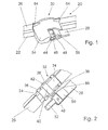
- eine perspektivische Teilansicht eines montierten Wischblatts von oben,
- Fig. 2
- im Wesentlichen eine Ansicht nach Fig. 1, jedoch ohne Kappe,
- Fig. 3
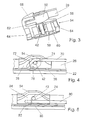
- eine perspektivische Teilansicht einer Kappe nach Fig. 1 mit einer Wischstange und einer Gelenkachse von unten,
- Fig. 4
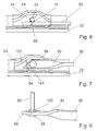
- eine Seitenansicht eines Wischblatts und einer Wischstange, die an ihrem Ende zum Gummiprofil hin abgeknickt ist,
- Fig. 5
- eine Seitenansicht eines Wischblatts und einer geraden Wischstange, die unterhalb der Gelenkachse verläuft,
- Fig. 6
- eine Variante zu Fig. 5,
- Fig. 7
- eine Seitenansicht eines Wischblatts und einer Wischstange, deren Ende um ihre Längsachse um 90° gedreht verläuft und deren über die Gelenkachse hinausragender Teil zum Gummiprofil hin abgeschrägt ist,
- Fig. 8
- eine Wischstange mit einer Gelenkachse nach Fig. 7 in einer Draufsicht,
- Fig. 9
- eine Gelenkachse nach Fig. 8,
- Fig. 10
- eine perspektivische Draufsicht eines Wischblatts und einer Wischstange im Ausschnitt, deren freies Ende gabelförmig gestaltet ist, und mit einem Führungszapfen an der Kappe zusammenwirkt,
- Fig. 11
- eine Variante nach Fig. 10, jedoch ohne Kappe,
- Fig. 12
- eine Seitenansicht eines Wischblatts und einer geraden Wischstange, die unterhalb der Gelenkachse verläuft und in einer Tasche der Kappe auf der Antriebsseite des Wischarms vor der Gelenkachse geführt ist,
- Fig. 13 und 14
- Varianten zu Fig. 12,
- Fig. 15
- eine perspektivische Teilansicht der Ausführung nach Fig. 14 von oben, jedoch ohne Kappe,
- Fig. 16
- eine Gelenkachse nach Fig. 15,
- Fig. 17
- eine Gelenkachse nach Fig. 18,
- Fig. 18
- eine perspektivische Teilansicht eines Wischarms und eines Wischblatts mit einer Gelenkachse nach Fig. 17 von unten,
- Fig. 19
- eine perspektivische Ansicht einer Kappe schräg von oben,
- Fig. 20
- eine Gelenkachse passend zur einer Kappe nach Fig. 19,
- Fig. 21
- eine Variante zu Fig. 20,
- Fig. 22
- eine perspektivische Teilansicht eines Wischblatts mit einem Verbindungsstück und einer darin festsitzenden Gelenkachse von oben,
- Fig. 23
- eine Ansicht einer Ausführung nach Fig. 22, mit einer Wischstange schräg von unten,
- Fig. 24
- eine perspektivische Ansicht einer Kappe mit einer Wischstange für eine Ausführung nach Fig. 22 von unten,
- Fig. 25
- eine Variante zu Fig. 25 und
- Fig. 26
- eine Gelenkachse nach Fig. 25.
- Fig. 1
- a partial perspective view of a mounted wiper blade from above,
- Fig. 2
- essentially a view according to FIG. 1, but without cap,
- Fig. 3
- 1 is a partial perspective view of a cap according to FIG. 1 with a wiper rod and a hinge axle from below, FIG.
- Fig. 4
- a side view of a wiper blade and a wiper rod, which is bent at its end to the rubber profile,
- Fig. 5
- a side view of a wiper blade and a straight wiper rod which extends below the hinge axis,
- Fig. 6
- a variant of FIG. 5,
- Fig. 7
- a side view of a wiper blade and a wiper rod, whose end is rotated about its longitudinal axis by 90 ° and whose protruding beyond the hinge axis part is tapered towards the rubber profile,
- Fig. 8
- a wiper rod with a hinge axis according to Fig. 7 in a plan view,
- Fig. 9
- a hinge axis according to Fig. 8,
- Fig. 10
- a top perspective view of a wiper blade and a wiper rod in the cutout whose free end is fork-shaped, and cooperates with a guide pin on the cap,
- Fig. 11
- a variant of FIG. 10, but without cap,
- Fig. 12
- a side view of a wiper blade and a straight wiper rod which extends below the hinge axis and is guided in a pocket of the cap on the drive side of the wiper arm in front of the hinge axis,
- FIGS. 13 and 14
- Variants to FIG. 12,
- Fig. 15
- a partial perspective view of the embodiment of FIG. 14 from above, but without cap,
- Fig. 16
- a hinge axis according to FIG. 15,
- Fig. 17
- a hinge axis according to Fig. 18,
- Fig. 18
- a partial perspective view of a wiper arm and a wiper blade with a hinge axis of FIG. 17 from below,
- Fig. 19
- a perspective view of a cap obliquely from above,
- Fig. 20
- a hinge axis suitable for a cap according to FIG. 19,
- Fig. 21
- a variant of FIG. 20,
- Fig. 22
- 3 a perspective partial view of a wiper blade with a connecting piece and a joint axis fixed therein from above,
- Fig. 23
- a view of an embodiment of FIG. 22, with a wiper rod obliquely from below,
- Fig. 24
- a perspective view of a cap with a wiper rod for an embodiment of FIG. 22 from below,
- Fig. 25
- a variant of Fig. 25 and
- Fig. 26
- a joint axis according to FIG. 25.
Ein gelenkloses Wischblatt 20 besitzt ein Gummiprofil 22, das an einem flachen Tragelement 24 befestigt ist. Dieses besteht in der Regel aus einer oder zwei Federleisten, die in dem oberen Teil des Gummiprofils 22 eingelassen sind. Zum gelenkigen Verbinden des Wischblatts 20 mit einer Wischstange 28 eines nicht näher dargestellten Wischarms ist im mittleren Bereich des Wischblatts 20 ein Gelenk 30 vorgesehen. Dieses besitzt als Verbindungsteil eine Blechkralle 32, deren Rücken 34 das Tragelement 24 überspannt und mit Rastnasen 36 an diesem befestigt ist. Die Rastnasen 36 können in Längsrichtung über das Tragelement 24 geschoben werden oder als Klippverbindung ausgebildet sein und durch elastisches Verformen quer zum Tragelement 24 aufgeklippst werden. Zwischen den Rastnasen 36, die an den Enden der Blechkralle 32 seitlich vorgesehen sind, stehen an den Längsseiten 66 der Blechkralle 32 Seitenwangen 38 vom Gummiprofil 22 abgewandt ab. Sie halten ein Lagerrohr 40, das quer zum Wischblatt 20 und etwa parallel zu einer nicht dargestellten Fahrzeugscheibe verläuft. In das Lagerrohr 40 ist eine Gelenkachse 42 gesteckt, die an einer Seite zur Wischstange 28 hin mit einem Kopf 44 aus dem Lagerrohr 40 herausragt.A
Die Wischstange 28 besitzt einen rechteckigen Querschnitt, wobei die längeren Seiten etwa parallel zur Gelenkachse 42 verlaufen. Bei den Ausführungen nach Fig. 1 bis 3 greift die Wischstange 28 in einen Schlitz 46 des Kopfes 44 der Gelenkachse 42 ein und ist durch einen Querstift 48 gesichert. Die Wischstange 28 ragt mit einem Finger 52 über den Schlitz 46 hinaus. Der Finger 52 ist schmaler als die Wischstange 28 und liegt an der dem Wischblatt 20 zugewandten Seite der Wischstange 28.The
In Längsrichtung gesehen sind zu beiden Seiten der Blechkralle 32 Teile eines Spoilers 26 an dem Tragelement 24 befestigt, die bei einer Anströmung durch den Fahrtwind den Anpressdruck auf die Fahrzeugscheibe erhöhen. Die Blechkralle 32 wird von einer Kappe 54 überdeckt, die sich mit Anschlussprofilen 64 harmonisch an die Teile des Spoilers 26 anschließt. Die Kappe 54 ist lösbar an der Blechkralle 32 befestigt. Sie besitzt hierzu an der Innenseite ihrer Seitenwände 60 Rastnasen 56, die in entsprechende Öffnungen 104 (Fig. 11) bzw. Vertiefungen der Blechkralle 32 einrasten. Außerdem besitzt sie in ihrem mittleren Bereich einen Klipp 58 zum Befestigen auf dem Lagerrohr 40. Die Gelenkachse 42 ragt mit ihrem Ende, das dem Kopf 44 abgewandt ist (Fig. 2), über die Seitenwange 38 hinaus, wobei dieses Ende in eine Vertiefung der Seitenwand 60 der Kappe 54 eingreift (Fig. 3) und somit deren Halt auf der Blechkralle 32 unterstützt.Seen in the
Die Kappe 54 besitzt an der Seite der Wischstange 28 eine zur Fahrzeugscheibe hin offene Tasche 62 (Fig. 3), in die der Finger 52 der Wischstange 28 in der Betriebsstellung eingreift, in der das Wischblatt 20 an der Fahrzeugscheibe anliegt. Eine Außenwand 68 der Tasche 62 verhindert, dass sich die Wischstange 28 mit ihrem Finger 52 nach außen bewegt, so dass die Gelenkachse 42 in axialer Richtung verriegelt ist. Die Tasche 62 wird weit gehend von einer Abdeckung 50 abgedeckt, die auf der Gelenkachse 42 sitzt und sich harmonisch an die Kontur der Wischstange 28 und der Kappe 54 anschließt. Die Abdeckung 50 ist gleichzeitig ein Aufprallschutz bzw.The
Dämpfungselement. Sie verhindert eine Beschädigung der Fahrzeugscheibe, falls der Wischarm bei einem Wechsel des Wischblatts versehentlich 20 auf die Fahrzeugscheibe schlägt.Damping element. It prevents damage to the vehicle window if the wiper arm accidentally strikes the vehicle window when the wiper blade is changed.
Die Ausführungen nach Fig. 4 bis Fig. 6 zeigen Wischstangen 70, 80, die durch Schweißnähte 74 mit einem Ende der Gelenkachse 42 verbunden sind. Die Wischstange 70 nach Fig. 4 verläuft oberhalb der Gelenkachse 42 und ragt mit einem zum Gummiprofil 22 hin abgewinkelten Ende 72 über die Gelenkachse 42 hinaus. Das abgewinkelte Ende 72 greift in der gezeigten Betriebsstellung des Wischblatts 20 in eine Tasche 76 der Kappe 54 ein, wobei der zum Wischarm 70 weisende Rand 78 der Kappe 54 so verläuft, dass das Wischblatt 20 in einer in Pfeilrichtung um ca. 90° gedrehten Position leicht von der Gelenkachse 42 abgezogen werden kann. In dieser Stellung wird das Wischblatt 20 auch montiert, indem es auf die Gelenkachse 42 gesteckt und anschließend in entgegengesetzter Richtung geschwenkt wird. In gleicher Weise werden die Wischblätter 20 nach Fig. 1, Fig. 5 bis Fig. 7, Fig. 10 und Fig. 11 montiert und demontiert. Durch die Abwinklung des Endes 72 kann die Tasche 76 flach ausgebildet werden, wodurch der Windwiderstand verringert und der optische Eindruck verbessert wird.The embodiments according to FIGS. 4 to 6
Einen gleichen Effekt erzielt man, wenn die Wischstange 80 bei den Ausführungen nach Fig. 5 und Fig. 6 unterhalb der Gelenkachse 42 verläuft und mit ihrem geraden, über die Gelenkachse 42 hinaus verlängerten Ende 82 in eine Tasche 84 der Kappe 54 eingreift. Auch hierbei ist der Rand 86 der Tasche 84 so ausgebildet, dass in der geschwenkten Montagestellung eine Montage oder Demontage leicht möglich ist. Während bei den Ausführungen nach Fig. 4 und Fig. 5 das Wischblatt 20 bei der Montage um ca. 90° gedreht werden muss, kann das Wischblatt 20 bei der Ausführung nach Fig. 6 bereits bei einem kleineren Schwenkwinkel montiert und demontiert werden. Dies wird dadurch erreicht, dass der Rand 88 der Tasche 84 unter einem geringeren Winkel zur Längsrichtung des Wischblatts 20 verläuft.A similar effect is achieved when the
Die Ausführung nach Fig. 7 ermöglicht ein sehr schmales Gelenk 30, indem die Wischstange 90 an ihrem Ende 92 in Längsrichtung um etwa 90° geschränkt ist, so dass die längeren Seiten ihres rechteckigen Profils im Bereich der Gelenkachse 96 quer zu dieser verlaufen. Das über die Gelenkachse 96 hinausragende Ende besitzt eine Abschrägung 94, die zum Gummiprofil 22 hin geneigt verläuft und greift mit der Abschrägung 94 in eine Tasche 122 der Kappe 54. Zur Montage und Demontage ist der Rand 124 der Tasche 122 entsprechend ausgebildet. Die Gelenkachse 96 (Fig. 9) besitzt einen gerändelten Sitz 100, auf den die Wischstange 90 mit einer Aufnahmeöffnung bis an einen Bund 98 gepresst und durch eine Scheibe 102 gesichert ist.The embodiment according to FIG. 7 enables a very narrow joint 30 in that the
Bei den Ausführungen nach Fig. 10 und Fig. 11 ist das über die Gelenkachse 42 hinausragende Ende der Wischstangen 118 als Gabel 112 ausgebildet, die in der dargestellten Betriebsstellung einen Führungszapfen 116 der Kappe 114 umfasst. Um die Kappe 114 flach gestalten zu können, ist es zweckmäßig, dass die Gabel 112 zum Gummiprofil 22 hin geneigt verläuft. Während die Wischstange 118 nach Fig. 16 wie bei der Ausführung nach Fig. 1 in einem Schlitz 46 des Kopfes 44 der Gelenkachse 42 gesteckt und durch einen Querstift 48 gesichert ist, besitzt die Wischstange 118 nach Fig. 11 eine Nabe 120, die auf dem freien Ende der Gelenkachse 42 sitzt und durch einen Querstift 48 gesichert ist. Grundsätzlich kann die Wischstange 118 auch wie die Wischstangen der zuvor beschriebenen Ausführungen mit der Gelenkachse 42 verschweißt sein.In the embodiments according to FIGS. 10 and 11, the end of the
Die Ausführungen nach Fig. 12 bis Fig. 15 und Fig. 18 gleichen den Ausführungen nach Fig. 5 und Fig. 6. Auch hier verlaufen die Wischstangen 80 und 136 unterhalb der Gelenkachsen 42 bzw. 106 und 138. Während die Wischstange 80 nach Fig. 12 und Fig. 13 an dem freien Ende der Gelenkachse 42 angeschweißt ist, besitzt die Gelenkachse 138 nach Fig. 14 und Fig. 15 einen flachen Kopf 140 mit zwei Nietlöchern 142, der durch Niete 144 mit der Wischstange 136 verbunden ist (Fig. 15). Die Gelenkachse 106 (Fig. 17) besitzt einen flachen Kopf 108, an dem ein Vierkant 110 angeformt ist, der in eine entsprechende Öffnung der Wischstange 136 eingepresst ist und ggf. in einem Taumelverfahren vernietet wird (Fig. 18).The embodiments according to FIGS. 12 to 15 and 18 are similar to the embodiments according to FIGS. 5 and 6. Here again, the
Die Kappen 54 für die Ausführungen nach Fig. 12 bis Fig. 15 und Fig. 18 besitzen auf der Seite zur Wischstange 80, 136 Taschen 126, die die Wischstange 80, 136 auf ihrer Antriebsseite vor der Gelenkachse 42, 106, 138 umfassen, so dass die Wischstange 80, 136 nicht über die Gelenkachse 42, 106, 138 hinausragen muss. So lassen sich sehr flach bauende Wischblätter 20 erzielen, wobei die Kappe 54 sehr flach und geschlossen ausgeführt werden kann. Zwischen der Tasche 126 und dem vorderen Teil der Kappe 128 bleibt nur ein kleines Montagefenster 132 in der äußeren Seitenwand offen. Während die Montagefenster 132 nach Fig. 12 und Fig. 14 einen Rand 130 aufweisen, der etwa senkrecht zum Gummiprofil 22 verläuft, ist der Rand 134 des Montagefensters 132 nach Fig. 13 zum Gummiprofil 22 so geneigt, dass eine Montage und Demontage des Wischblatts 20 unter einem Winkel erfolgen kann, der kleiner ist als 90°. Zur Demontage ist das Wischblatt 20 in Richtung des Pfeiles zu schwenken, der in Fig. 12 eingezeichnet ist.The
Bei einer anderen Ausführung besitzt die Gelenkachse 178 (Fig. 20, 21) zur Wischstange 28, 90 hin zwei diametral zueinander angeordnete Flügel 180, 182, die sich radial zur Gelenkachse 28, 90 und in Längsrichtung der zugeordneten Wischstange 28, 90 erstrecken. Die Gelenkachse 178 nach Fig. 20 besitzt wie die Gelenkachse 42 nach Fig. 1 einen Schlitz 46 in einem Kopf 44, in den die Wischstange 28 eingesetzt und durch einen Querstift, z.B. eine Niete, gesichert ist. Die Gelenkwelle 178 nach Fig. 21 besitzt stirnseitig einen Nietzapfen 178, mit dem sie an der Wischstange 90 befestigt ist, die wie die Wischstange 90 nach Fig. 8 in Längsrichtung um 90° gedreht ist. In beiden Fällen greifen die Flügel 180, 182 in montierter Stellung des Wischblatts 20 in entsprechend ausgerichtete Taschen 184, 186 einer Tasche 190 (Fig. 19) nach Art eines Bajonettverschlusses ein. Durch Drehen des Wischblatts 20 um 90° kann der Bajonettverschluss zur Demontage gelöst oder bei der Montage geschlossen werden.In another embodiment, the hinge axis 178 (Fig. 20, 21) to the
Während bei den bisher beschriebenen Ausführungen die Gelenkachse 42, 96, 106, 138 drehbar in dem Lagerrohr 40 der Blechkralle 32 gelagert und mit der Wischstange 20, 70, 80, 90, 118, 136 verbunden ist, ist die Gelenkachse 146, 164 drehfest mit der Blechkralle 32 und drehbar mit der Wischstange 150 verbunden, z.B. indem sie mit einem unrunden Querschnittprofil in Form eines Vielkants oder abgeflachten Zylinders in entsprechenden Öffnungen der Seitenwangen 38 gehalten wird. Bei der Ausführung nach Fig. 24 besitzt die Gelenkachse 146 ein halbrundes Querschnittprofil mit einer Abflachung 148, die zum Gummiprofil 22 weist. Sie ist drehfest in Öffnungen der Seitenwangen 38 der Blechkralle 32 eingesetzt und trägt an ihrem seitlich zur Wischstange 150 vorstehenden Ende drehfest eine Lagerhülse 154, die an ihrem äußeren Umfang einen zylindrischen Bereich 156 aufweist und zum Gummiprofil 22 hin einen abgeflachten Bereich 158 haben kann. Auf der Lagerhülse 154 ist ein entsprechend gebogenes Ende 152 der Wischstange 150 drehbar gelagert (Fig. 23). Das gebogene Ende 152 kann auch unmittelbar auf einem rund oder halbrund profilierten Teil der Gelenkwelle 146, 164 gelagert sein. Die Lagerhülse 154 und das Ende 152 der Wischstange 150 werden in einer Lagertasche 162 einer Kappe 160 geführt. Die Kappe 160 ist mittels Rastnasen 56 und eines Klipps 58 an der Blechkralle 32 bzw. an der Gelenkachse 146 befestigt. Außerdem steht die Gelenkachse 146 über die Lagerhülse 154 vor und greift in eine Vertiefung 176 der Kappe 160 ein. Das Wischblatt 20 kann an der Wischstange 150 montiert werden, indem es mit der montierten Kappe 160 so weit gedreht wird, dass das gebogene Ende 152 zwischen Kappe 160 und Lagerhülse 154 eingefädelt werden kann.While in the embodiments described so far, the
Die Variante nach Fig. 24 besitzt eine Gelenkachse 164 mit einem Befestigungsbereich 166, der einen im Wesentlichen rechteckigen Querschnitt und einen quer zu den längeren Seiten verlaufenden Längsschnitt 168 aufweist. Die längeren Seiten des Querschnittprofils verlaufen etwa parallel zum Tragelement 24. An den äußeren Seiten sind an den Enden des Befestigungsbereichs 166 Rastnasen 170 vorgesehen, die durch eine Öffnung in der zugeordneten Seitenwange 38 ragen und mit dem Rand dieser Öffnung verrasten. Zum anderen Ende weist die Gelenkachse 164 einen Lagerbereich 172 auf, der von zwei Bünden 174 in axialer Richtung begrenzt wird. Auf dem Lagerbereich 172 ist das gebogene Ende 152 der Wischstange 150 gelagert und wird durch die Lagertasche 152 der Kappe 160 in der montierten Position gesichert.The variant according to FIG. 24 has a
- 2020
- Wischblattwiper blade
- 2222
- Gummiprofilrubber profile
- 2424
- Tragelementsupporting member
- 2626
- Spoilerspoiler
- 2828
- Wischstangewiper rod
- 3030
- Gelenkjoint
- 3232
- Blechkrallesheet metal claw
- 3434
- Rückenmove
- 3636
- Rastnaselocking lug
- 3838
- Seitenwangeside cheek
- 4040
- Lagerrohrbearing tube
- 4242
- Gelenkachsejoint axis
- 4444
- Kopfhead
- 4646
- Schlitzslot
- 4848
- Querstiftcross pin
- 5050
- Abdeckungcover
- 5252
- Fingerfinger
- 5454
- Kappecap
- 5656
- Rastnaselocking lug
- 5858
- Klippclip
- 6060
- SeitenwandSide wall
- 6262
- Taschebag
- 6464
- Anschlussprofilconnection profile
- 6666
- Längsseitelong side
- 6868
- Außenwandouter wall
- 7070
- Wischstangewiper rod
- 7272
- EndeThe End
- 7474
- SchweißnahtWeld
- 7676
- Taschebag
- 7878
- Randedge
- 8080
- Wischstangewiper rod
- 8282
- EndeThe End
- 8484
- Taschebag
- 8686
- Randedge
- 8888
- Randedge
- 9090
- Wischstangewiper rod
- 9292
- geschränktes Endelimited end
- 9494
- Abschrägungbevel
- 9696
- Gelenkachsejoint axis
- 9898
- BundFederation
- 100100
- SitzSeat
- 102102
- Scheibedisc
- 104104
- Rastvertiefunglatching depression
- 106106
- Gelenkachsejoint axis
- 108108
- Kopfhead
- 110110
- Vielkantpolyhedron
- 112112
- Gabelfork
- 114114
- Kappecap
- 116116
- Führungszapfenspigot
- 118118
- Wischstangewiper rod
- 120120
- Nabehub
- 122122
- Taschebag
- 124124
- Randedge
- 126126
- Taschebag
- 128128
- Kappecap
- 130130
- Randedge
- 132132
- Montagefenstermounting window
- 134134
- Randedge
- 136136
- Wischstangewiper rod
- 138138
- Gelenkachsejoint axis
- 140140
- Kopfhead
- 142142
- Nietlochrivet hole
- 144144
- Nietrivet
- 146146
- Gelenkachsejoint axis
- 148148
- Abflachungflattening
- 150150
- Wischstangewiper rod
- 152152
- EndeThe End
- 154154
- Lagerhülsebearing sleeve
- 156156
- zylindrischer Bereichcylindrical area
- 158158
- abgeflachter Bereichflattened area
- 160160
- Kappecap
- 162162
- Lagertaschebearing pocket
- 164164
- Gelenkachsejoint axis
- 166166
- Befestigungsbereichfastening area
- 168168
- Längsschlitzlongitudinal slot
- 170170
- Rastnaselocking lug
- 172172
- Lagerbereichstorage area
- 174174
- BundFederation
- 176176
- Vertiefungdeepening
- 178178
- Gelenkachsejoint axis
- 180180
- Flügelwing
- 182182
- Flügelwing
- 184184
- Taschebag
- 186186
- Taschebag
- 188188
- Nietzapfenrivet
- 190190
- Kappecap
Claims (27)
- Wiper blade (20) with a connecting part (32) which is mounted on a carrying element (24) of the wiper blade (20) and has a pivot pin (42, 96, 106, 138, 146, 164, 178) of a joint (30), the free end of which can be connected to a wiper rod (28, 70, 80, 90, 118, 136, 150), characterized in that the joint (30) comprises a cap (54, 114, 128, 160, 190), which covers and is attached to the connecting part (32) and which during operation secures the wiper blade (20) and the wiper rod (28, 70, 80, 90, 118, 136, 150) in the fitted position, the cap (54, 114, 128, 160) having a pocket (62, 76, 84, 122, 126, 164) which faces the wiper rod (28, 70, 80, 90, 118, 136, 150) and is open towards the windscreen and towards the wiper rod (28, 70, 80, 90, 118, 136, 150) in the longitudinal direction thereof, and which overlaps the latter laterally.
- Wiper blade (20) according to one of the preceding claims, characterized in that a spoiler (26) is attached to the carrying element (24) in the longitudinal direction on both sides of the connecting part (32), the cap (54, 114, 128, 160, 190) with an adjoining profile (64) harmoniously adjoining parts of said spoiler.
- Wiper blade (20) according to Claim 2, characterized in that the cap (54, 114, 128, 160, 190) with its adjoining profiles (64) results in a substantially continuous spoiler (26).
- Wiper blade (20) according to Claim 3, characterized in that the top of the cap (54, 114, 128, 160, 190) is cambered on its trailing edge between the adjoining profiles (64). (Fig. 1 and Fig. 4)
- Wiper blade (20) according to one of Claims 2 to 4, characterized in that the leading edge of the spoiler (26) faces the wiper rod (28).
- Wiper blade (20) according to one of the preceding claims, characterized in that the pivot pin (42, 96, 106, 138, 178) is rotatably mounted in the connecting part (32), which takes the form of a sheet metal claw and is attached to the carrying element (24) by means of catches (36) mounted laterally on the back (34) thereof.
- Wiper blade (20) according to Claim 6, characterized in that the sheet metal claw (32) has raised side faces (38) on its longitudinal sides (66), said faces being connected by a bearing tube (40) in which the pivot pin (42, 96, 106, 138, 178) is rotatably mounted. (Fig. 2)
- Wiper blade (20) according to either of Claims 6 or 7, characterized in that the cap (54, 114, 128, 160, 190) is held on the sheet metal claw (32) by means of catches (56), which engage in catch recesses (104) in the side faces (38) of the sheet metal claw (32) (Fig. 11).
- Wiper blade (20) according to either of Claims 7 or 8, characterized in that the cap (54, 114, 128, 160, 190) has a clip (58) in the area of the bearing tube (42) by means of which it is attached to the bearing tube (40) or the pivot pin (164).
- Wiper blade (20) according to one of Claims 7 to 9, characterized in that the pivot pin (42, 96, 106, 138, 146, 164, 190) at one end protrudes beyond a side face (38) of the sheet metal claw (32) and is rotationally locked to the wiper rod (28, 70, 80, 90, 118, 136), while the other end thereof protruding slightly beyond the associated side face (38) engages in a recess in the cap (54, 114, 128, 160, 190) (Fig. 2, Fig. 3 and Fig. 24).
- Wiper blade (20) according to one of the preceding claims, characterized in that the wiper rod (28., 70, 80, 90, 118) is extended beyond the pivot pin (42, 96), and with its extended part is guided in a pocket (62, 76, 84, 122) or on a guide pin (116) of the cap (54, 114). (Fig. 1 to Fig. 11)
- Wiper blade (20) according to Claim 11, characterized in that the protruding part of the wiper rod (28, 70, 80, 118) is angled towards the rubber profile (22).
- Wiper blade (20) according to one of the preceding claims, characterized in that the wiper blade (80, 136, 150) runs beneath the pivot pin (42, 106, 138, 146, 164) and above the rubber profile (22).
- Wiper blade (20) according to one of the preceding claims, characterized in that the pivot pin (42, 96, 106, 138) is connected to the wiper rod (28) by means of a weld (74). (Fig. 4 to Fig. 6 and Fig. 11, Fig. 12)
- Wiper blade (20) according to one of Claims 1 to 13, characterized in that the pivot pin (42, 178) has a head (44) facing the wiper rod (28, 118), said head having a slot (46) to accommodate the wiper rod (28, 118) which is secured in the slot (46) by means of a cross pin (48). (Fig. 1, Fig. 10, Fig. 20)
- Wiper blade (20) according to one of Claims 1 to 13, characterized in that at its end facing the pivot pin (96) the wiper rod (90) is rotated by approximately 90 degrees about its longitudinal axis so that its broad side runs transversely to the pivot pin (96). (Fig. 8, Fig. 21)
- Wiper blade (20) according to Claim 16, characterized in that the pivot pin (96), with a collar (98) at the end thereof, bears against the wiper rod (90), which is pressed against a knurled seat (100) adjoining the collar (98) and is secured by a washer (102). (Fig. 8, Fig. 9)
- Wiper blade (20) according to either of Claims 16 or 17, characterized in that the wiper rod (90), at the end protruding beyond the pivot pin (96), has a bevel (94) towards the rubber profile (22), and in its operating position engages with the bevelled part in a pocket (122) of the cap (54).
- Wiper blade (20) according to one of Claims 1 to 15, characterized in that the cap (114) has a guide pin (116), which laterally faces the wiper rod (118) and engages in the end of the wiper rod (118) which takes the form of a fork (112). (Fig. 10, Fig. 11)
- Wiper blade (20) according to one of the preceding claims, characterized in that the pocket (126) of the cap (128) is arranged between the pivot pin (42, 138) and the drive-side end of the wiper rod (80, 136) and overlaps the latter laterally. (Fig. 12 to Fig. 14)
- Wiper blade (20) according to one of the preceding claims, characterized in that the pivot pin (138) has a flat head (140) with two rivet holes (142) facing the wiper blade and riveted by rivets (144) to the wiper rod (136). (Fig. 15)
- Wiper blade (20) according to one of the preceding claims, characterized in that the pivot pin (106) has a flat head (108), onto which a transversely extending polygonal element (110) is integrally formed, the latter being pressed into a matching opening in the wiper rod (136) and the protruding part thereof being wobble-riveted. (Fig. 18)
- Wiper blade (20) according to one of the preceding claims, characterized in that the pivot pin (178) has two diametrically opposed wings (180, 182) extending radially to the pivot pin (178) and in the longitudinal direction of the wiper blade (28, 90) and in the fitted state engaging in correspondingly aligned lateral pockets (184, 186) of the cap (190) in the manner of a bayonet lock. (Fig. 19 to 21)
- Wiper blade (20) according to one of the preceding claims, characterized in that the pivot pin (146) having a non-circular cross-sectional profile is held rotationally locked in corresponding openings in the side faces (38) in the sheet metal claw (32), a correspondingly bent end (152) of the wiper rod (150) being pivotally mounted on the part thereof which protrudes towards the wiper rod (150) and being guided in a bearing pocket (162) of the cap (160).
- Wiper blade (20) according to Claim 25, characterized in that the pivot pin (146) has a semicircular profile with a flattened area (148) facing the rubber profile (22) and is held rotationally locked in corresponding openings in the side faces (38) in the sheet metal claw (32), a bearing bushing (154) with a matching cylindrical area (156) and a flattened area (158) being rotationally locked on the part which protrudes towards the wiper rod (150), the correspondingly bent end (152) of the wiper rod (150) being pivotally mounted on said bushing. (Fig. 24)
- Wiper blade (20) according to Claim 24, characterized in that the pivot pin (146) engages with its free end in a recess (176) in a side wall of the bearing pocket (162).
- Wiper blade (20) according to either of Claims 24 or 26, characterized in that the pivot pin (164) has a bearing area (172) between two axial collars (174), on which area the bent part (152) of the wiper rod (150) is mounted, and has a fastening area (156) with a rectangular cross-sectional profile and a longitudinal slot (158), which on the outsides of its ends has catches (170) by means of which it is latched in a corresponding opening in the associated side face (38). (Fig. 25 and Fig. 26)
Applications Claiming Priority (5)
| Application Number | Priority Date | Filing Date | Title |
|---|---|---|---|
| DE10229608 | 2002-06-28 | ||
| DE10229608 | 2002-06-28 | ||
| DE10259480 | 2002-12-19 | ||
| DE10259480A DE10259480A1 (en) | 2002-06-28 | 2002-12-19 | wiper blade |
| PCT/DE2003/001638 WO2004002792A1 (en) | 2002-06-28 | 2003-05-20 | Wiper blade |
Publications (2)
| Publication Number | Publication Date |
|---|---|
| EP1519862A1 EP1519862A1 (en) | 2005-04-06 |
| EP1519862B1 true EP1519862B1 (en) | 2007-02-21 |
Family
ID=30001501
Family Applications (1)
| Application Number | Title | Priority Date | Filing Date |
|---|---|---|---|
| EP03761402A Expired - Lifetime EP1519862B1 (en) | 2002-06-28 | 2003-05-20 | Wiper blade |
Country Status (7)
| Country | Link |
|---|---|
| US (1) | US7546660B2 (en) |
| EP (1) | EP1519862B1 (en) |
| JP (1) | JP4295212B2 (en) |
| BR (1) | BR0312013A (en) |
| DE (1) | DE50306589D1 (en) |
| ES (1) | ES2280795T3 (en) |
| WO (1) | WO2004002792A1 (en) |
Cited By (5)
| Publication number | Priority date | Publication date | Assignee | Title |
|---|---|---|---|---|
| US8806700B2 (en) | 2011-07-29 | 2014-08-19 | Pylon Manufacturing Corporation | Wiper blade connector |
| US9108595B2 (en) | 2011-07-29 | 2015-08-18 | Pylon Manufacturing Corporation | Windshield wiper connector |
| US9457768B2 (en) | 2011-04-21 | 2016-10-04 | Pylon Manufacturing Corp. | Vortex damping wiper blade |
| US9505380B2 (en) | 2014-03-07 | 2016-11-29 | Pylon Manufacturing Corp. | Windshield wiper connector and assembly |
| USD777079S1 (en) | 2014-10-03 | 2017-01-24 | Pylon Manufacturing Corp. | Wiper blade frame |
Families Citing this family (38)
| Publication number | Priority date | Publication date | Assignee | Title |
|---|---|---|---|---|
| DE10259480A1 (en) * | 2002-06-28 | 2004-01-15 | Robert Bosch Gmbh | wiper blade |
| DE10259856B4 (en) * | 2002-12-20 | 2016-06-30 | Robert Bosch Gmbh | Wiper arm of a wiper device for windows of motor vehicles |
| DE102004016017A1 (en) * | 2004-04-01 | 2005-10-20 | Bosch Gmbh Robert | wiper blade |
| DE102004019157A1 (en) * | 2004-04-21 | 2005-11-10 | Robert Bosch Gmbh | wiper blade |
| DE102004030429A1 (en) * | 2004-06-24 | 2006-01-19 | Valeo Wischersysteme Gmbh | Connection between a wiper arm and a wiper blade and windshield wiper assembly |
| DE202005005406U1 (en) * | 2005-03-31 | 2006-01-19 | Karl Storz Gmbh & Co. Kg | Medical instrument with contoured journal |
| US7774892B2 (en) | 2005-04-04 | 2010-08-17 | Trico Products Corporation | Wiper coupler and wiper assembly incorporating same |
| CA2541641C (en) | 2005-04-04 | 2014-02-11 | Trico Products Corporation | Wiper coupler and wiper assembly incorporating same |
| JP4641915B2 (en) * | 2005-09-29 | 2011-03-02 | 株式会社ミツバ | Wiper blade |
| DE102005050569A1 (en) * | 2005-10-21 | 2007-04-26 | Robert Bosch Gmbh | Connecting device for a wiper arm |
| DE102006004110A1 (en) * | 2006-01-28 | 2007-08-16 | Valeo Systèmes d`Essuyage | wiper arm |
| US20080028564A1 (en) * | 2006-08-04 | 2008-02-07 | Shu-Lan Ku | Wiper blade support structure |
| US8122560B2 (en) * | 2006-08-04 | 2012-02-28 | Dongguan Hongyi Wiper Co., Ltd. | Windshield wiper bridge base assembly |
| US8042218B2 (en) | 2007-04-05 | 2011-10-25 | Trico Products Corporation | Wiper assembly having side-saddle coupler |
| DE102009001809A1 (en) * | 2009-03-24 | 2010-09-30 | Robert Bosch Gmbh | Connection device for the articulated connection of a wiper arm with a wiper blade according to a Sidelockprinzip |
| KR101105340B1 (en) * | 2009-08-21 | 2012-01-16 | 주식회사 캐프 | How to Assemble Metal Clamps and Body Springs for Automotive Wiper Blades |
| US8533899B2 (en) | 2009-08-27 | 2013-09-17 | Trico Products Corporation | Windshield wiper assembly |
| US8397341B2 (en) | 2010-05-13 | 2013-03-19 | Trico Products Corporation | Beam blade windshield wiper assembly |
| US8261403B2 (en) | 2010-05-13 | 2012-09-11 | Trico Products Corporation | Beam blade windshield wiper assembly |
| US8495787B2 (en) | 2010-08-03 | 2013-07-30 | Rally Manufacturing, Inc. | Windshield wiper |
| US9174609B2 (en) | 2011-04-21 | 2015-11-03 | Pylon Manufacturing Corp. | Wiper blade with cover |
| MX345011B (en) | 2011-07-28 | 2017-01-11 | Pylon Mfg Corp | Windshield wiper adapter, connector and assembly. |
| MX364943B (en) | 2012-02-24 | 2019-05-14 | Pylon Mfg Corp | Wiper blade. |
| US20130219649A1 (en) | 2012-02-24 | 2013-08-29 | Pylon Manufacturing Corp. | Wiper blade |
| JP6126797B2 (en) * | 2012-05-24 | 2017-05-10 | アスモ株式会社 | Wiper |
| US10829092B2 (en) | 2012-09-24 | 2020-11-10 | Pylon Manufacturing Corp. | Wiper blade with modular mounting base |
| USD704618S1 (en) | 2012-11-15 | 2014-05-13 | Trico Products Corporation | Wiper blade |
| USD702618S1 (en) | 2012-11-15 | 2014-04-15 | Trico Products Corporation | Wiper blade coupler |
| US9221429B2 (en) | 2012-11-15 | 2015-12-29 | Trico Products Corporation | Wiper coupler assembly and wiper assembly incorporating same |
| US9533655B2 (en) | 2012-12-04 | 2017-01-03 | Trico Products Corporation | Wiper coupler adapter and wiper assembly incorporating same |
| US9260084B2 (en) | 2013-01-03 | 2016-02-16 | Trico Products Corporation | Wiper coupler adapter and wiper assembly incorporating same |
| US10166951B2 (en) | 2013-03-15 | 2019-01-01 | Pylon Manufacturing Corp. | Windshield wiper connector |
| US9227599B2 (en) | 2013-05-02 | 2016-01-05 | Trico Products Corporation | Mounting assembly for wiper blade and wiper arm |
| US9493140B2 (en) | 2013-12-02 | 2016-11-15 | Trico Products Corporation | Coupler assembly for wiper assembly |
| US9434355B2 (en) | 2014-04-01 | 2016-09-06 | Trico Products Corporation | Wiper adapter and wiper assembly incorporating the same |
| US9539987B2 (en) | 2014-04-01 | 2017-01-10 | Trico Products Corporation | Wiper adapter and wiper assembly incorporating the same |
| US9663071B2 (en) | 2014-05-29 | 2017-05-30 | Trico Products Corporation | Wiper adapter and wiper assembly incorporating same |
| FR3031712B1 (en) * | 2015-01-16 | 2018-10-12 | Valeo Systemes D'essuyage | ICE WIPER COVER CONFIGURE TO COVER A TERMINAL PART OF A WIPER ARM |
Family Cites Families (16)
| Publication number | Priority date | Publication date | Assignee | Title |
|---|---|---|---|---|
| GB1443699A (en) | 1972-08-15 | 1976-07-21 | Blackburn J | Production of reinforced grass on root impermeable surfaces |
| CH595230A5 (en) * | 1976-01-27 | 1978-02-15 | J B Brevets | |
| JPS5361934A (en) | 1976-11-16 | 1978-06-02 | Fujitsu Ltd | Ternary logical circuit using josephson junction device |
| US4118825A (en) * | 1977-03-28 | 1978-10-10 | Monroe Auto Equipment Company | Connector assembly for windshield wipers |
| DE2830508A1 (en) | 1978-07-12 | 1980-01-31 | Bosch Gmbh Robert | Rapid coupling for windscreen blade - with lateral axis and securing cam on side of blade |
| IT1144605B (en) | 1981-06-09 | 1986-10-29 | Arman Spa | ATTACK DEVICE FOR WINDSCREEN WIPERS |
| US4416032A (en) * | 1981-10-05 | 1983-11-22 | Mohnach Michael G | Connector adaptor for pin-type blade |
| EP0136218A3 (en) | 1983-08-29 | 1988-04-20 | FAIRCHILD CAMERA & INSTRUMENT CORPORATION | Multiple port pipelined processor |
| FR2705074B1 (en) | 1993-05-11 | 1995-06-23 | Journee Paul Sa | WIPER DEVICE, ESPECIALLY FOR MOTOR VEHICLES. |
| DE19729865A1 (en) | 1997-07-11 | 1999-01-14 | Bosch Gmbh Robert | Windshield wipers for motor vehicles |
| DE19739256A1 (en) | 1997-09-08 | 1999-03-11 | Bosch Gmbh Robert | Wiper blade for cleaning windows of motor vehicles |
| DE19856299A1 (en) * | 1998-12-07 | 2000-06-08 | Bosch Gmbh Robert | Hinged device for connection of wiper blade to windscreens of motor vehicles has wind deflector strip on upper surface of support element that extends on both sides of connecting element in blade's longitudinal direction |
| DE19924662B4 (en) | 1999-05-28 | 2007-06-28 | Robert Bosch Gmbh | Wiper device for windows of motor vehicles |
| DE10000374A1 (en) | 2000-01-07 | 2001-07-12 | Valeo Auto Electric Gmbh | Wiper blade arrangement esp. for cleaning front- and rear windows of motor vehicles, includes an adapter for connecting wiper blade to wiper arm and having a bearing boring positioned normal to length of wiper blade |
| DE10036135A1 (en) | 2000-07-25 | 2002-02-28 | Volkswagen Ag | Vehicle windscreen wiper has blade holding block with bearing for pivot bolt and securing hook |
| DE10057253A1 (en) * | 2000-11-18 | 2002-05-23 | Bosch Gmbh Robert | Wiper lever for motor vehicle's windscreen wiper system has cap for covering connecting section between wiper blade and wiper arm and in cross section is approximately U-shape and made from elastic plastic |
-
2003
- 2003-05-20 BR BR0312013-9A patent/BR0312013A/en not_active IP Right Cessation
- 2003-05-20 EP EP03761402A patent/EP1519862B1/en not_active Expired - Lifetime
- 2003-05-20 WO PCT/DE2003/001638 patent/WO2004002792A1/en not_active Ceased
- 2003-05-20 US US10/519,728 patent/US7546660B2/en not_active Expired - Fee Related
- 2003-05-20 ES ES03761402T patent/ES2280795T3/en not_active Expired - Lifetime
- 2003-05-20 JP JP2004516457A patent/JP4295212B2/en not_active Expired - Fee Related
- 2003-05-20 DE DE50306589T patent/DE50306589D1/en not_active Expired - Lifetime
Cited By (5)
| Publication number | Priority date | Publication date | Assignee | Title |
|---|---|---|---|---|
| US9457768B2 (en) | 2011-04-21 | 2016-10-04 | Pylon Manufacturing Corp. | Vortex damping wiper blade |
| US8806700B2 (en) | 2011-07-29 | 2014-08-19 | Pylon Manufacturing Corporation | Wiper blade connector |
| US9108595B2 (en) | 2011-07-29 | 2015-08-18 | Pylon Manufacturing Corporation | Windshield wiper connector |
| US9505380B2 (en) | 2014-03-07 | 2016-11-29 | Pylon Manufacturing Corp. | Windshield wiper connector and assembly |
| USD777079S1 (en) | 2014-10-03 | 2017-01-24 | Pylon Manufacturing Corp. | Wiper blade frame |
Also Published As
| Publication number | Publication date |
|---|---|
| JP4295212B2 (en) | 2009-07-15 |
| DE50306589D1 (en) | 2007-04-05 |
| WO2004002792A1 (en) | 2004-01-08 |
| US20050251946A1 (en) | 2005-11-17 |
| BR0312013A (en) | 2005-03-22 |
| EP1519862A1 (en) | 2005-04-06 |
| US7546660B2 (en) | 2009-06-16 |
| JP2005536385A (en) | 2005-12-02 |
| ES2280795T3 (en) | 2007-09-16 |
Similar Documents
| Publication | Publication Date | Title |
|---|---|---|
| EP1519862B1 (en) | Wiper blade | |
| DE10259480A1 (en) | wiper blade | |
| EP1846274B1 (en) | Device for the pivoting connection of a wiper blade to a wiper arm of a windscreen wiper | |
| EP1940660B1 (en) | Windscreen wiper arm | |
| EP1461235B1 (en) | Windscreen wiper comprising a wiper arm | |
| EP1037779B1 (en) | Device for connecting a wiper blade for windshields in motor vehicles to a wiper arm | |
| EP0929423B1 (en) | Motor vehicle window wiper | |
| EP1363816B1 (en) | Wiper arm with a pivoting connected wiper blade | |
| EP1585657B1 (en) | Wiping device for windows of motor vehicles | |
| EP1824714B1 (en) | Wiper arm and cover for a wiper arm | |
| EP1098796A1 (en) | Wiper device for motor vehicle windows | |
| EP1877290A1 (en) | Wiper blade | |
| DE19731683A1 (en) | windshield wipers | |
| EP1824717B1 (en) | Wiper blade | |
| DE10349637A1 (en) | Articulated joint for use between wiper arm and blade, has base cap closing window between spoiler parts and closing two parallel side walls of adaptor from outside to provide closed interconnection between cap and adaptor | |
| WO2012100896A1 (en) | Device for the articulated connection of a flat-bar wiper blade to a wiper arm | |
| DE3724777A1 (en) | WIPER ARMS, ESPECIALLY FOR MOTOR VEHICLE WIPER SYSTEMS | |
| DE69705138T2 (en) | Windshield wipers for motor vehicles with trim for end piece | |
| EP1045780B1 (en) | Windscreen wiper | |
| DE10162397B4 (en) | wiper blade | |
| DE102004017941A1 (en) | Device for connecting wiper blade with wiper arm has securing device with at least one securing part protruding from wiper blade on wiper blade side with toggle bar locking device | |
| DE10305322B4 (en) | wiper blade | |
| EP1606150B1 (en) | Articulated arm with a wiper rod | |
| DE102007024557A1 (en) | Wiper blade mounting at the wiper arm, for a vehicle windscreen, has a hook with an adapter across the blade when in place to reduce the mounting height | |
| DE69404888T2 (en) | Wipers with a wedge |
Legal Events
| Date | Code | Title | Description |
|---|---|---|---|
| PUAI | Public reference made under article 153(3) epc to a published international application that has entered the european phase |
Free format text: ORIGINAL CODE: 0009012 |
|
| 17P | Request for examination filed |
Effective date: 20050128 |
|
| AK | Designated contracting states |
Kind code of ref document: A1 Designated state(s): AT BE BG CH CY CZ DE DK EE ES FI FR GB GR HU IE IT LI LU MC NL PT RO SE SI SK TR |
|
| RBV | Designated contracting states (corrected) |
Designated state(s): DE ES FR GB HU IT |
|
| GRAP | Despatch of communication of intention to grant a patent |
Free format text: ORIGINAL CODE: EPIDOSNIGR1 |
|
| GRAS | Grant fee paid |
Free format text: ORIGINAL CODE: EPIDOSNIGR3 |
|
| GRAA | (expected) grant |
Free format text: ORIGINAL CODE: 0009210 |
|
| AK | Designated contracting states |
Kind code of ref document: B1 Designated state(s): DE ES FR GB HU IT |
|
| REG | Reference to a national code |
Ref country code: GB Ref legal event code: FG4D Free format text: NOT ENGLISH |
|
| REF | Corresponds to: |
Ref document number: 50306589 Country of ref document: DE Date of ref document: 20070405 Kind code of ref document: P |
|
| GBT | Gb: translation of ep patent filed (gb section 77(6)(a)/1977) |
Effective date: 20070514 |
|
| ET | Fr: translation filed | ||
| REG | Reference to a national code |
Ref country code: ES Ref legal event code: FG2A Ref document number: 2280795 Country of ref document: ES Kind code of ref document: T3 |
|
| PLBE | No opposition filed within time limit |
Free format text: ORIGINAL CODE: 0009261 |
|
| STAA | Information on the status of an ep patent application or granted ep patent |
Free format text: STATUS: NO OPPOSITION FILED WITHIN TIME LIMIT |
|
| 26N | No opposition filed |
Effective date: 20071122 |
|
| PG25 | Lapsed in a contracting state [announced via postgrant information from national office to epo] |
Ref country code: IT Free format text: LAPSE BECAUSE OF FAILURE TO SUBMIT A TRANSLATION OF THE DESCRIPTION OR TO PAY THE FEE WITHIN THE PRESCRIBED TIME-LIMIT Effective date: 20070221 |
|
| PGFP | Annual fee paid to national office [announced via postgrant information from national office to epo] |
Ref country code: ES Payment date: 20090522 Year of fee payment: 7 |
|
| PGFP | Annual fee paid to national office [announced via postgrant information from national office to epo] |
Ref country code: FR Payment date: 20090519 Year of fee payment: 7 |
|
| PG25 | Lapsed in a contracting state [announced via postgrant information from national office to epo] |
Ref country code: HU Free format text: LAPSE BECAUSE OF FAILURE TO SUBMIT A TRANSLATION OF THE DESCRIPTION OR TO PAY THE FEE WITHIN THE PRESCRIBED TIME-LIMIT Effective date: 20070822 |
|
| PGFP | Annual fee paid to national office [announced via postgrant information from national office to epo] |
Ref country code: GB Payment date: 20090528 Year of fee payment: 7 |
|
| GBPC | Gb: european patent ceased through non-payment of renewal fee |
Effective date: 20100520 |
|
| REG | Reference to a national code |
Ref country code: FR Ref legal event code: ST Effective date: 20110131 |
|
| PG25 | Lapsed in a contracting state [announced via postgrant information from national office to epo] |
Ref country code: FR Free format text: LAPSE BECAUSE OF NON-PAYMENT OF DUE FEES Effective date: 20100531 |
|
| REG | Reference to a national code |
Ref country code: ES Ref legal event code: FD2A Effective date: 20110711 |
|
| PG25 | Lapsed in a contracting state [announced via postgrant information from national office to epo] |
Ref country code: ES Free format text: LAPSE BECAUSE OF NON-PAYMENT OF DUE FEES Effective date: 20110629 Ref country code: GB Free format text: LAPSE BECAUSE OF NON-PAYMENT OF DUE FEES Effective date: 20100520 |
|
| PG25 | Lapsed in a contracting state [announced via postgrant information from national office to epo] |
Ref country code: ES Free format text: LAPSE BECAUSE OF NON-PAYMENT OF DUE FEES Effective date: 20100521 |
|
| PGFP | Annual fee paid to national office [announced via postgrant information from national office to epo] |
Ref country code: DE Payment date: 20190716 Year of fee payment: 17 |
|
| REG | Reference to a national code |
Ref country code: DE Ref legal event code: R119 Ref document number: 50306589 Country of ref document: DE |
|
| PG25 | Lapsed in a contracting state [announced via postgrant information from national office to epo] |
Ref country code: DE Free format text: LAPSE BECAUSE OF NON-PAYMENT OF DUE FEES Effective date: 20201201 |