EP1670302B1 - Frame - Google Patents
Frame Download PDFInfo
- Publication number
- EP1670302B1 EP1670302B1 EP05020692A EP05020692A EP1670302B1 EP 1670302 B1 EP1670302 B1 EP 1670302B1 EP 05020692 A EP05020692 A EP 05020692A EP 05020692 A EP05020692 A EP 05020692A EP 1670302 B1 EP1670302 B1 EP 1670302B1
- Authority
- EP
- European Patent Office
- Prior art keywords
- frame structure
- structure according
- members
- frame
- depth
- Prior art date
- Legal status (The legal status is an assumption and is not a legal conclusion. Google has not performed a legal analysis and makes no representation as to the accuracy of the status listed.)
- Not-in-force
Links
Images

Classifications
-
- H—ELECTRICITY
- H05—ELECTRIC TECHNIQUES NOT OTHERWISE PROVIDED FOR
- H05K—PRINTED CIRCUITS; CASINGS OR CONSTRUCTIONAL DETAILS OF ELECTRIC APPARATUS; MANUFACTURE OF ASSEMBLAGES OF ELECTRICAL COMPONENTS
- H05K7/00—Constructional details common to different types of electric apparatus
- H05K7/18—Construction of rack or frame
Definitions
- the invention relates to a frame according to the preamble of claim 1.
- the invention is particularly suitable for equipment cabinets, which are used for the establishment of local networks and are designed to hold electrical, electronic and optoelectronic devices, components and components and relatively large amounts of cable and cables with different diameters.
- Known frame racks for equipment cabinets have an upper and lower horizontal frame of two depth and cross beams.
- the frames are connected to each other in corner areas by four vertical beams, thereby forming a receiving space for devices, components and cables.
- trim parts e.g. a front door, side walls, a rear wall, a cover and a floor panel are attached to form a fully enclosed equipment cabinet.
- a frame with four vertical profiles or two lateral support walls which connect an upper cover plate and a lower base plate.
- the top plate and base plate have mounting holes and are provided with two front and rear aligned cantilevers, through which a front and rear cutout for harnesses is formed.
- a cable assembly can be done on the relatively open, equipped with the components frame.
- WO 99/48305 A1 a frame for a telecommunications and network cabinet is described, in which an upper and a lower horizontal, rectangular frame are connected by two vertical profiles. Assembly of the assemblies, devices, cable blocks, etc. is done on vertical front and rear mounting posts, which have mounting holes of the appropriate standard and are attached to additional lower and upper horizontal cross sections.
- Out GB 2 345 240 B is a frame for a device cabinet with two or four vertical beams known, which are connected at the top and bottom by two transverse bars.
- the two transverse beams are U-shaped and connected to each other in the region of their transverse webs or form an elongated, centrally connected cross.
- the known frame racks which are relatively expensive to produce, are not always sufficient to meet the requirements for unobstructed cabling and vertical and horizontal cable management with free access to the wiring areas, especially in cabinet rows with side-by-side cabinets.
- the invention has for its object to provide a frame for equipment cabinets, in particular the network and telecommunication technology and for rows of cabinets, which ensures an unimpeded transfer of relatively large quantities of cables and of different flexibility as well as a vertical and horizontal cable guide without threading in a cost-effective manufacture and assembly ,
- a basic idea of the invention can be seen in the provision of a self-supporting construction of a base frame in which four depth beams, two vertical beams and two transverse beams are arranged and connected in such a way that an extremely stable and at the same time dismantlable base frame is created, which allows unhindered wiring of a large base frame Number of cables and a cable guide in the vertical and horizontal directions and in particular from a cabinet to an adjacent cabinet with free access to wiring areas from all sides guaranteed.
- a right and left vertical spar is connected at each of the upper and lower end with an upper and lower spar, so that a right and left double-T frame is formed.
- connection of the vertical beams to the upper and lower spar rail is carried out by welding, and the unit thus formed is advantageous for the storage, transport and installation of the frame.
- the frame according to the invention can also be regarded as H-frame, in which the depth members form the vertical webs and the transverse struts the horizontal web.
- the right and left double-T frame can be regarded as a H-frame after a 90 ° rotation, in particular, when the vertical spar is respectively centrally connected to the upper and lower spar and thus is arranged as a central spar.
- the required stability of the frame according to the invention is achieved by multi-folded or bent vertical beams and trained as C and / or U-beam depth and cross beams.
- open multi-chamber profiles can be used as vertical beams, which have a rectangular contour with relatively narrow short sides and approximately two to four times longer longitudinal sides.
- open multi-chamber profiles such as three-chamber profiles, can be conveniently prepared from a sheet steel blank roll-roll or bending process and can in addition to their supporting Function nor for cable management and / or attachment of cable management components, such as cable trays and the like, serve.
- the provided in the direction of a receiving space with at least one central opening and a front and rear inner leg vertical bars offer connection points for rails and accessories, such as 19 "accessories, such as socket strips and the like.
- Further attachment openings can advantageously also be formed in the narrow short sides of the vertical profiles in order to be able to fasten accessories, mounting rails, devices, assemblies and cable management components.
- a cable guide or recording of cables is further possible in the region of the outer longitudinal side of the vertical struts, wherein the cables can be inserted via a front and rear longitudinal opening.
- connection of a vertical spar with an upper and lower spar rail end portions of the vertical beams are positively received in a corresponding recess of the respective depth spar and in particular welded.
- connection with depth beams with a C-shaped profile and a recess which is formed in an internally arranged horizontal leg and an upper and lower inner leg, so that a depth spar with its outer end portion on a vertical C-leg and the front side on an outside arranged horizontal leg rests.
- another Connection in the area of the upper and lower inner leg of the depth spars is another Connection in the area of the upper and lower inner leg of the depth spars.
- connection points for a hinge in particular for a pin hinge, as well as for a closure device, for example a closure hook, of a trim part arranged as a door.
- connection points are preferably provided on the front and on the end and may be formed, for example, on the outside horizontal legs as an angle with corresponding openings.
- the depth members of a sheet steel blank can be produced by Mehrfachbbiegungen and punching.
- the connection points integrated into the depth spars can furthermore serve for detachable fastening of a rear wall and side walls and a cover as well as a floor panel.
- U-shaped or C-shaped beams are used as transverse spars, which are arranged as the depth members with their opening directed towards each other.
- the width of the transverse spars may correspond to the depth of the vertical spars.
- the transverse bars on the front side each have a mounting plate which is formed substantially higher than the vertical legs of the U- or C-shaped transverse bars and has holes for the screw connection with the vertical bars of the right and left double-T frame.
- the mounting plates of the cross members are provided to increase the stability and support function with mounting brackets, which are bent at right angles and end portions of the vertical Leg and a respective horizontal edge web of the cross members include or abut against this.
- the frame structure according to the invention is advantageously used for different width frame racks or wiring cabinets, in an extremely simple way, only the cross beams must be adjusted in length.
- the lateral double T-frames can be taken over unchanged.
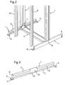
- Fig. 1 shows a frame 2, which ensures high stability and unobstructed cabling and cable routing in each direction and thus an advantageous use for network cabinets and cabinet rows with high wiring densities.
- the frame 2 comprises two vertical beams 3, four depth beams 4 and two transverse beams 5, which are arranged and connected to one another such that a front frame recess 8 and a rear frame recess 9 is formed.
- Fig. 1 and also the enlarged partial view of the Fig. 2 clarify that a cable guide without disadvantageous threading is possible because both the generally common front and back vertical bars and the front and back upper and lower crossbars omitted.
- a high stability and at the same time advantageous accessibility and cabling are achieved by the connection of a respective vertical member 3 to a lower member 4 secured to the upper and lower end, which form a double T-frame.
- the connection of the depth members 4 with end portions of the vertical beams 3 is preferably carried out by welded joints 10 of the vertical beams 3 used in recesses 30 of the depth members 4 (see also Fig. 3 ).
- the right 6 and left double T-frame 7 are interconnected by an upper and lower cross member 5, wherein an advantageous detachable screw 11 between the cross bars 5 and the depth members 4 of the right double-T frame 6 and the left double T-frame 7 is provided.
- Fig. 1 and Fig. 2 show the mirror-image arrangement of the right and left vertical beam 3, the upper and lower depth beams 4 and the upper and lower cross member 5, which define a receiving space 28 for electrical, electronic and also optoelectronic devices and cable guides (not shown).
- the depth beams 4 are each end with connection points 34 for the attachment of trim parts, such as a rear wall, two side walls, a cover and a bottom plate (not shown) and for a hinge and closure device of a door (not shown).
- trim parts such as a rear wall, two side walls, a cover and a bottom plate (not shown) and for a hinge and closure device of a door (not shown).
- the depth beams 4 are also designed for attachment of mounting rails 38, wherein this attachment can be performed directly or indirectly via adapter 39 and advantageously adjustable in depth.
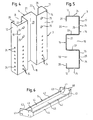
- Fig. 2 shows a foot-side portion of the frame 2 according to Fig. 1 , Identical features are provided with identical reference numerals.
- the enlarged partial view of the Fig. 2 shows more details and in particular the profile cross sections of the vertical beams 3, depth beams 4 and cross members 5 and the connecting portions 10, eleventh
- Fig. 3 is the left lower spar 4 according to Fig. 1 and 2 shown.
- the depth member 4 has a C-shaped cross-section which is formed by a vertical C-leg 35 arranged on the outside, perpendicular to this bent horizontal leg 36, 37 and bent at right angles inner legs 32, 33.
- a recess 30 for receiving an end portion of a vertical beam 3 (see Fig. 1 and 2 ) is formed centrally in this embodiment, by the inner side horizontal leg 37 and the bent inner leg 33 and the bent on the outside horizontal leg 36, bottom disposed inner leg 32 are not formed continuously.
- the recess 30 is dimensioned complementary to the end regions of the depth members 4 and ensures a positive reception and welding of the vertical leg C 37 and the outside horizontal leg 36 flatly adjacent and to the horizontal leg 37 and both inner leg 32, 33 adjacent vertical beam.
- connection points 34 may be formed as inwardly directed angle with different openings 31.
- FIG. 4 shows an upper portion of the left vertical beam 3 according to Fig. 1
- Fig. 5 a cross section of this vertical beam 3 is shown.
- FIGS. 4 and 5 illustrate the formation of the vertical bars 3 as open three-chamber profiles, which can be prepared by Mehrfachabkantungen or -abbiegungen a blank.
- the vertical bars 3 have a rectangular contour with a front and back short side 12, 13 and an inner and outer longitudinal side 14, 15.
- the inner longitudinal side 14 comprises a front-side inner leg 16 and a rear-side inner leg 17, between which a central opening 18 due to bent transverse limbs 22, 23 and an outer connecting leg 21 is formed.
- Through the center opening 18 can be advantageously inserted and laid cables.
- a cable guide is also possible in the region of the outer longitudinal side 15, which has a front-side opening 19 and a rear-side opening 20 due to approximately right-angled bends.
- 20 protrude short leg 26, which are formed as right-angled bends of the front short side 12 and the rear short side 13.
- Attachment openings 24 are formed both in the short sides 12, 13 and in the front and rear inner legs 16, 17.
- mounting holes 25 for the screw 11 which serve the connection of the right double-T frame 6 and the left double-T frame 7 with the upper and lower cross member 5.
- Fig. 6 shows that the mounting holes 25 complementary to holes 41 in frontally arranged mounting plates 40th the transverse bars 5 are formed.
- four holes 41 in the cross member 5 and in the mounting plates 40 and correspondingly four mounting holes 25 in the vertical leg 3 and in the two inner legs 16, 17 are formed.
- the crossbar according to Fig. 6 is upwardly or downwardly open and formed in cross-section U- or C-shaped and has on both sides of a horizontally disposed leg 45 vertical leg 44 and bevelled horizontal edge webs 42, which are directed inward and end of mounting brackets 43 are included.
- the mounting brackets 43 are formed as a chamfered 90 ° folds of the mounting plates 40, which contribute to increasing the support and support function.
Landscapes
- Engineering & Computer Science (AREA)
- Microelectronics & Electronic Packaging (AREA)
- Tables And Desks Characterized By Structural Shape (AREA)
- Casings For Electric Apparatus (AREA)
- Patch Boards (AREA)
- Holders For Apparel And Elements Relating To Apparel (AREA)
- Ladders (AREA)
- Audible-Bandwidth Dynamoelectric Transducers Other Than Pickups (AREA)
- Compressor (AREA)
- Magnetic Resonance Imaging Apparatus (AREA)
Abstract
Description
Die Erfindung betrifft ein Rahmengestell gemäß dem Oberbegriff des Anspruchs 1.The invention relates to a frame according to the preamble of claim 1.
Die Erfindung ist insbesondere für Geräteschränke geeignet, welche zur Errichtung lokaler Netze eingesetzt werden und zur Aufnahme elektrischer, elektronischer und optoelektronischer Geräte, Bauteile und Komponenten und relativ großer Kabelmengen sowie von Kabeln mit unterschiedlich großen Durchmessern ausgebildet sind.The invention is particularly suitable for equipment cabinets, which are used for the establishment of local networks and are designed to hold electrical, electronic and optoelectronic devices, components and components and relatively large amounts of cable and cables with different diameters.
Bekannte Rahmengestelle für Geräteschränke weisen einen oberen und unteren horizontalen Rahmen aus jeweils zwei Tiefen- und Querholmen auf. Die Rahmen werden in Eckbereichen durch vier Vertikalholme miteinander verbunden und dadurch ein Aufnahmeraum für Geräte, Bauteile und Kabel gebildet. An dem Rahmengestell können Verkleidungsteile, z.B. eine Fronttür, Seitenwände, eine Rückwand, eine Abdeckung und ein Bodenblech angebracht werden, um einen allseitig geschlossenen Geräteschrank auszubilden.Known frame racks for equipment cabinets have an upper and lower horizontal frame of two depth and cross beams. The frames are connected to each other in corner areas by four vertical beams, thereby forming a receiving space for devices, components and cables. On the frame, trim parts, e.g. a front door, side walls, a rear wall, a cover and a floor panel are attached to form a fully enclosed equipment cabinet.
Für Anwendungen mit großen Kabelmengen und für Kabel mit relativ großen Durchmessern und geringer Biegbarkeit sind Rahmengestelle erforderlich, welche einen freien Zugang für die Kabel in den Aufnahmeraum und eine ungehinderte Verkabelung und Kabelführung mit einem möglichst allseitigen Zugriff zu den Verkabelungsbereichen ermöglichen.For applications with large amounts of cable and for cables with relatively large diameters and low flexibility frame frames are required, which allow free access for the cables in the receiving space and unhindered wiring and cable management with the most complete access to the wiring areas.
Aus
In
Aus
Aus
Die bekannten Rahmengestelle, welche relativ aufwändig herzustellen sind, genügen nicht in jedem Fall den Anforderungen an eine ungehinderte Verkabelung und vertikale und horizontale Kabelführung mit freiem Zugriff zu den Verkabelungsbereichen, insbesondere bei Schrankreihen mit seitlich aneinandergrenzenden Schränken.The known frame racks, which are relatively expensive to produce, are not always sufficient to meet the requirements for unobstructed cabling and vertical and horizontal cable management with free access to the wiring areas, especially in cabinet rows with side-by-side cabinets.
Der Erfindung liegt die Aufgabe zugrunde, ein Rahmengestell für Geräteschränke, insbesondere der Netzwerk- und Telekommunikationstechnik sowie für Schrankreihen, zu schaffen, welches bei einer kostengünstigen Herstellung und Montage eine ungehinderte Verlegung relativ großer Kabelmengen und unterschiedlicher Biegbarkeit sowie eine vertikale und horizontale Kabelführung ohne Einfädeln gewährleistet.The invention has for its object to provide a frame for equipment cabinets, in particular the network and telecommunication technology and for rows of cabinets, which ensures an unimpeded transfer of relatively large quantities of cables and of different flexibility as well as a vertical and horizontal cable guide without threading in a cost-effective manufacture and assembly ,
Erfindungsgemäß wird die Aufgabe durch die Merkmale des Anspruchs 1 gelöst. Zweckmäßige und vorteilhafte Ausgestaltungen sind in den Unteransprüchen und in den Zeichnungen beschrieben.According to the invention the object is achieved by the features of claim 1. Advantageous and advantageous embodiments are described in the subclaims and in the drawings.
Ein Grundgedanke der Erfindung kann darin gesehen werden, eine selbst tragende Konstruktion eines Grundrahmens zu schaffen, bei welchem vier Tiefenholme, zwei Vertikalholme und zwei Querholme derart angeordnet und verbunden werden, dass ein außerordentlich stabiler und gleichzeitig zerlegbarer Grundrahmen entsteht, welcher eine ungehinderte Verkabelung einer großen Anzahl von Kabeln sowie eine Kabelführung in vertikaler und horizontaler Richtung und insbesondere von einem Schrank zu einem angrenzenden Schrank mit einem freien Zugriff zu Verkabelungsbereichen von allen Seiten gewährleistet.A basic idea of the invention can be seen in the provision of a self-supporting construction of a base frame in which four depth beams, two vertical beams and two transverse beams are arranged and connected in such a way that an extremely stable and at the same time dismantlable base frame is created, which allows unhindered wiring of a large base frame Number of cables and a cable guide in the vertical and horizontal directions and in particular from a cabinet to an adjacent cabinet with free access to wiring areas from all sides guaranteed.
Erfindungsgemäß wird ein rechter und linker Vertikalholm jeweils am oberen und unteren Ende mit einem oberen und unteren Tiefenholm verbunden, so dass ein rechter und linker Doppel-T-Rahmen gebildet ist.According to the invention a right and left vertical spar is connected at each of the upper and lower end with an upper and lower spar, so that a right and left double-T frame is formed.
Bevorzugt erfolgt die Verbindung der Vertikalholme mit dem oberen und unteren Tiefenholm durch Verschweißen, und die derart gebildete Einheit ist vorteilhaft für die Lagerung, den Transport und die Montage des Rahmengestells.Preferably, the connection of the vertical beams to the upper and lower spar rail is carried out by welding, and the unit thus formed is advantageous for the storage, transport and installation of the frame.
Der rechte und linke Doppel-T-Rahmen wird erfindungsgemäß im Verbindungsbereich der Vertikalholme und Tiefenholme unter Ausbildung einer front- und rückseitigen Rahmenausnehmung durch einen oberen und unteren Querholm verbunden, wobei eine lösbare Verbindung, beispielsweise eine Schraubverbindung, für eine zerlegbare und beispielsweise als flat-Pack lieferbare Konstruktion vorteilhaft ist.The right and left double T-frame according to the invention in the connecting region of the vertical beams and depth beams to form a front and back Rahmenausnehmung connected by an upper and lower cross member, with a detachable connection, such as a screw, for a collapsible and, for example, as flat Pack available construction is advantageous.
In Draufsicht kann das erfindungsgemäße Rahmengestell auch als H-Rahmen angesehen werden, bei welchem die Tiefenholme die vertikalen Stege und die Querholme den horizontalen Steg bilden.In plan view, the frame according to the invention can also be regarded as H-frame, in which the depth members form the vertical webs and the transverse struts the horizontal web.
Auch der rechte und linke Doppel-T-Rahmen kann nach einer 90°-Drehung als H-Rahmen angesehen werden, insbesondere, wenn der Vertikalholm jeweils mittig mit dem oberen und unteren Tiefenholm verbunden wird und somit als ein Mittelholm angeordnet ist.Also, the right and left double-T frame can be regarded as a H-frame after a 90 ° rotation, in particular, when the vertical spar is respectively centrally connected to the upper and lower spar and thus is arranged as a central spar.
Indem die bei bekannten Schrankkonstruktionen jeweils in Eckbereichen angeordneten Vertikalholme entfallen und front- und rückseitige Rahmenausnehmungen ohne störende front- und rückseitige Querholme gebildet sind, ist eine ungehinderte Verkabelung und vertikale Kabelführung von oben bzw. von unten sowie horizontale Kabelführung von links und/oder rechts sowie von einem Schrank zu einem angrenzenden Schrank, beispielsweise bei Schrankreihen, gewährleistet. Eine Einfädelung von Kabeln, welche aufwändig und insbesondere bei Kabeln mit entsprechendem Durchmesser schwierig zu handhaben ist, wird vermieden.By eliminating arranged in known cabinet structures each in corner areas vertical struts and front and rear frame recesses are formed without disturbing front and back crossbars, unhindered cabling and vertical cable management from above or from below and horizontal cable routing from the left and / or right and from a cupboard to an adjacent cupboard, for example in rows of cupboards. A threading of cables, which is complex and difficult to handle, especially for cables with a corresponding diameter, is avoided.
Außerdem ist ein ungehinderter Zugriff zu Verkabelungsbereichen von im Wesentlichen allen Seiten, insbesondere von vorn und von der Seite her möglich.In addition, unhindered access to cabling areas of substantially all sides, especially from the front and from the side, is possible.
Die erforderliche Stabilität des erfindungsgemäßen Rahmengestells wird durch mehrfach abgekantete bzw. abgebogene Vertikalholme und als C- und/oder U-Träger ausgebildete Tiefen- und Querholme erreicht.The required stability of the frame according to the invention is achieved by multi-folded or bent vertical beams and trained as C and / or U-beam depth and cross beams.
Besonders vorteilhaft können offene Mehrkammerprofile als Vertikalholme eingesetzt werden, welche eine rechteckige Kontur mit relativ schmalen Kurzseiten und etwa zwei- bis viermal längeren Längsseiten aufweisen. Durch Mehrfachabkantungen oder -abbiegungen gebildete, offene Mehrkammerprofile, beispielsweise Dreikammerprofile, können zweckmäßigerweise aus einem Stahlblechzuschnitt im Rollformverfahren oder auch im Biegeverfahren hergestellt werden und können neben ihrer tragenden Funktion noch zur Kabelführung und/oder Befestigung von Kabelmanagement-Komponenten, beispielsweise von Kabelwannen und dergleichen, dienen. Außerdem bieten die in Richtung eines Aufnahmeraumes mit wenigstens einer Mittenöffnung und einem frontseitigen und rückseitigen Innenschenkel versehenen Vertikalholme Anbindungspunkte für Profilschienen und Zubehör, beispielsweise 19" Zubehör, wie Dosenleisten und dergleichen.Particularly advantageous open multi-chamber profiles can be used as vertical beams, which have a rectangular contour with relatively narrow short sides and approximately two to four times longer longitudinal sides. Formed by Mehrfachabkantant or -bbiegungen, open multi-chamber profiles, such as three-chamber profiles, can be conveniently prepared from a sheet steel blank roll-roll or bending process and can in addition to their supporting Function nor for cable management and / or attachment of cable management components, such as cable trays and the like, serve. In addition, the provided in the direction of a receiving space with at least one central opening and a front and rear inner leg vertical bars offer connection points for rails and accessories, such as 19 "accessories, such as socket strips and the like.
In den frontseitigen und rückseitigen Innenschenkeln, welche mit einer Mittenöffnung eine Innenseite der Vertikalholme bilden, können zweckmäßigerweise Befestigungsöffnungen rasterartig und dem jeweiligen Standard entsprechend ausgebildet sein. In einem oberen und unteren Bereich sind außerdem zweckmäßigerweise Löcher für Schraubverbindungen vorgesehen, welche der lösbaren Verbindung mit den Querholmen dienen.In the front and rear inner legs, which form an inner side of the vertical struts with a central opening, it is expedient for fastening openings to be constructed in a grid-like manner and in accordance with the respective standard. In an upper and lower area expediently holes are provided for screw, which serve the releasable connection with the crossbars.
Weitere Befestigungsöffnungen können vorteilhafterweise auch in den schmalen Kurzseiten der Vertikalprofile ausgebildet werden, um Zubehör, Montageholme, Geräte, Baugruppen und Kabelmanagement-Komponenten befestigen zu können.Further attachment openings can advantageously also be formed in the narrow short sides of the vertical profiles in order to be able to fasten accessories, mounting rails, devices, assemblies and cable management components.
Eine Kabelführung bzw. Aufnahme von Kabeln ist des Weiteren im Bereich der äußeren Längsseite der Vertikalholme möglich, wobei die Kabel über eine frontseitige und rückseitige Längsöffnung eingeführt werden können.A cable guide or recording of cables is further possible in the region of the outer longitudinal side of the vertical struts, wherein the cables can be inserted via a front and rear longitudinal opening.
Zur vorzugsweise festen Verbindung eines Vertikalholms mit einem oberen und unteren Tiefenholm werden Endbereiche der Vertikalholme in eine entsprechende Ausnehmung des jeweiligen Tiefenholms formschlüssig aufgenommen und insbesondere verschweißt. Vorteilhaft ist die Verbindung mit Tiefenholmen mit einem C-förmigen Profil und einer Ausnehmung, welche in einem innenseitig angeordneten Horizontalschenkel und einem oberen und unteren Innenschenkel ausgebildet ist, so dass ein Tiefenholm mit seinem außenseitigen Endbereich an einem vertikalen C-Schenkel und stirnseitig an einem außenseitig angeordneten Horizontalschenkel anliegt. Vorteilhaft erfolgt eine weitere Verbindung im Bereich des oberen und unteren Innenschenkels der Tiefenholme.For preferably fixed connection of a vertical spar with an upper and lower spar rail end portions of the vertical beams are positively received in a corresponding recess of the respective depth spar and in particular welded. Advantageously, the connection with depth beams with a C-shaped profile and a recess which is formed in an internally arranged horizontal leg and an upper and lower inner leg, so that a depth spar with its outer end portion on a vertical C-leg and the front side on an outside arranged horizontal leg rests. Advantageously, another Connection in the area of the upper and lower inner leg of the depth spars.
Es ist zweckmäßig, wenn die Tiefenholme mit Anbindungspunkten für eine Scharnierung, insbesondere für eine Stiftscharnierung, sowie für eine Verschlusseinrichtung, beispielsweise einen Verschlusshaken, eines als Tür angeordneten Verkleidungsteils versehen sind. Diese Anbindungspunkte sind bevorzugt frontseitig und endseitig vorgesehen und können beispielsweise an den außenseitigen Horizontalschenkeln als Winkel mit entsprechenden Öffnungen ausgebildet sein.It is expedient if the depth members are provided with connection points for a hinge, in particular for a pin hinge, as well as for a closure device, for example a closure hook, of a trim part arranged as a door. These connection points are preferably provided on the front and on the end and may be formed, for example, on the outside horizontal legs as an angle with corresponding openings.
Es ist von Vorteil, dass auch die Tiefenholme aus einem Stahlblechzuschnitt durch Mehrfachabbiegungen und Ausstanzungen hergestellt werden können. Die in die Tiefenholme integrierten Anbindungspunkte können weiterhin einer lösbaren Befestigung einer Rückwand sowie von Seitenwänden und einer Abdeckung sowie eines Bodenblechs dienen.It is advantageous that the depth members of a sheet steel blank can be produced by Mehrfachbbiegungen and punching. The connection points integrated into the depth spars can furthermore serve for detachable fastening of a rear wall and side walls and a cover as well as a floor panel.
Zweckmäßigerweise werden als Querholme U- oder C-förmige Träger eingesetzt, welche wie die Tiefenholme mit ihrer Öffnung zueinander gerichtet angeordnet werden. Beispielsweise kann die Breite der Querholme der Tiefe der Vertikalholme entsprechen. Eine vorteilhafte, lösbare Befestigung der Querholme erfolgt an den Tiefenholmen, wodurch die Zerlegbarkeit der Rahmenkonstruktion in zwei Doppel-T-Rahmen und die zwei Querholme und eine Lieferung als Flat-Pack gewährleistet sind.Conveniently, U-shaped or C-shaped beams are used as transverse spars, which are arranged as the depth members with their opening directed towards each other. For example, the width of the transverse spars may correspond to the depth of the vertical spars. An advantageous, releasable attachment of the crossbars takes place on the depth beams, whereby the dismantling of the frame structure in two double-T frame and the two transverse spars and a delivery as a flat pack are guaranteed.
Zur vorteilhaften Schraubbefestigung weisen die Querholme stirnseitig jeweils eine Befestigungsplatte auf, welche wesentlich höher als die vertikalen Schenkel der U- oder C-förmigen Querholme ausgebildet ist und Löcher für die Schraubverbindung mit den Vertikalholmen des rechten und linken Doppel-T-Rahmens aufweist.For advantageous screw fastening, the transverse bars on the front side each have a mounting plate which is formed substantially higher than the vertical legs of the U- or C-shaped transverse bars and has holes for the screw connection with the vertical bars of the right and left double-T frame.
Die Befestigungsplatten der Querholme sind zur Erhöhung der Stabilität und Tragfunktion mit Befestigungswangen versehen, welche rechtwinklig abgekantet sind und Endbereiche der vertikalen Schenkel und eines jeweils horizontalen Randsteges der Querholme umfassen bzw. an diesen anliegen.The mounting plates of the cross members are provided to increase the stability and support function with mounting brackets, which are bent at right angles and end portions of the vertical Leg and a respective horizontal edge web of the cross members include or abut against this.
Die erfindungsgemäße Rahmenkonstruktion ist vorteilhaft für unterschiedlich breite Rahmengestelle bzw. Verkabelungsschränke einsetzbar, wobei in einer außerordentlich einfachen Weise lediglich die Querholme längenmäßig angepasst werden müssen. Die seitlichen Doppel-T-Rahmen können unverändert übernommen werden.The frame structure according to the invention is advantageously used for different width frame racks or wiring cabinets, in an extremely simple way, only the cross beams must be adjusted in length. The lateral double T-frames can be taken over unchanged.
Es liegt im Rahmen der Erfindung, durch eine einfache Änderung der Ausnehmung in den Tiefenholmen die Vertikalholme außermittig zur Ausbildung von unterschiedlichen front- und rückseitigen Rahmenausnehmungen anzuordnen und zu verbinden.It is within the scope of the invention to arrange by a simple change of the recess in the depth beams, the vertical beams off-center to form different front and rear frame recesses and connect.
Die Erfindung wird nachstehend anhand einer Zeichnung weiter erläutert. In dieser zeigen in einer stark schematisierten Darstellung:
- Fig. 1
- eine perspektivische Darstellung eines erfindungsgemäßen Rahmengestells;
- Fig. 2
- eine vergrößerte Darstellung des fußseitigen Bereichs des erfindungsgemäßen Rahmengestells nach
Fig. 1 ; - Fig. 3
- eine perspektivische Darstellung eines Tiefenholms des erfindungsgemäßen Rahmengestells;
- Fig. 4
- eine perspektivische Darstellung eines oberen Bereichs eines Vertikalholms des erfindungsgemäßen Rahmengestells;
- Fig. 5
- einen Querschnitt des Vertikalholms nach
Fig. 4 und - Fig. 6
- eine perspektivische Darstellung eines Querholms.
- Fig. 1
- a perspective view of a frame according to the invention;
- Fig. 2
- an enlarged view of the foot-side portion of the frame according to the invention according to
Fig. 1 ; - Fig. 3
- a perspective view of a depth of spar of the frame according to the invention;
- Fig. 4
- a perspective view of an upper portion of a vertical spar of the frame according to the invention;
- Fig. 5
- a cross section of the vertical spar after
Fig. 4 and - Fig. 6
- a perspective view of a cross member.
Das Rahmengestell 2 umfasst zwei Vertikalholme 3, vier Tiefenholme 4 und zwei Querholme 5, welche derart angeordnet und miteinander verbunden sind, dass eine frontseitige Rahmenausnehmung 8 und eine rückseitige Rahmenausnehmung 9 gebildet wird.
Eine hohe Stabilität und gleichzeitig vorteilhafte Zugänglichkeit und Verkabelung werden erreicht durch die Verbindung jeweils eines Vertikalholms 3 mit einem am oberen und unteren Ende befestigten Tiefenholm 4, welche einen Doppel-T-Rahmen bilden. Die Verbindung der Tiefenholme 4 mit Endbereichen der Vertikalholme 3 erfolgt bevorzugt durch Schweißverbindungen 10 der in Ausnehmungen 30 der Tiefenholme 4 eingesetzten Vertikalholme 3 (siehe auch
Der rechte 6 und linke Doppel-T-Rahmen 7 werden durch einen oberen und unteren Querholm 5 miteinander verbunden, wobei eine vorteilhafte, lösbare Schraubverbindung 11 zwischen den Querholmen 5 und den Tiefenholmen 4 des rechten Doppel-T-Rahmens 6 und des linken Doppel-T-Rahmens 7 vorgesehen ist.The right 6 and left double T-
Die Tiefenholme 4 sind jeweils endseitig mit Anbindungspunkten 34 für die Befestigung von Verkleidungsteilen, beispielsweise einer Rückwand, zweier Seitenwände, einer Abdeckung und eines Bodenblechs (nicht dargestellt) sowie für eine Scharnierung und Verschlusseinrichtung einer Tür (nicht dargestellt) versehen.The depth beams 4 are each end with connection points 34 for the attachment of trim parts, such as a rear wall, two side walls, a cover and a bottom plate (not shown) and for a hinge and closure device of a door (not shown).
Die Tiefenholme 4 sind außerdem zur Befestigung von Montageholmen 38 ausgebildet, wobei diese Befestigung direkt oder indirekt über Adapter 39 und vorteilhafterweise in der Tiefe verstellbar durchgeführt werden kann.The depth beams 4 are also designed for attachment of mounting
In
Eine Ausnehmung 30 zur Aufnahme eines Endbereichs eines Vertikalholms 3 (siehe
Aus
Im Querschnitt weisen die Vertikalholme 3 eine rechteckige Kontur mit einer frontseitigen und rückseitigen Kurzseite 12, 13 und einer inneren und äußeren Längsseite 14, 15 auf. Die innere Längsseite 14 umfasst einen frontseitigen Innenschenkel 16 und einen rückseitigen Innenschenkel 17, zwischen denen eine Mittenöffnung 18 aufgrund von abgebogenen Querschenkeln 22, 23 und einem außenseitigen Verbindungsschenkel 21 gebildet ist. Durch die Mittenöffnung 18 können vorteilhaft Kabel eingeführt und verlegt werden. Eine Kabelführung ist auch im Bereich der äußeren Längsseite 15 möglich, welche aufgrund von etwa rechtwinkligen Abkantungen eine frontseitige Öffnung 19 und eine rückseitige Öffnung 20 aufweist. In diese frontseitige und rückseitige Öffnung 19, 20 ragen Kurzschenkel 26, welche als rechtwinklige Abkantungen der frontseitigen Kurzseite 12 und der rückseitigen Kurzseite 13 ausgebildet sind.In cross section, the
Befestigungsöffnungen 24 sind sowohl in den Kurzseiten 12, 13 als auch in dem frontseitigen und rückseitigen Innenschenkel 16, 17 ausgebildet. Außerdem sind Befestigungslöcher 25 für die Schraubverbindungen 11 (
Der Querholm gemäß
Claims (20)
- Frame structure
for cabinets, in particular for network cabinets and cabinet rows with high cabling densities,
having a right and a left-hand vertical member (3), two upper and lower depth members (4) and with an upper and a lower transverse member (5),
characterized in that
the right-hand and the left-hand vertical member (3) is in each case terminally connected to an upper and lower depth member (4) to form a right (6) and a left-hand double-T frame (7) and
that in the connecting area of the vertical members (3) and the depth members (4) the right (6) and left-hand double-T frame (7) are connected by the upper and lower transverse member (5), accompanied by the formation of a front (8) and a rear frame recess (9). - Frame structure according to claim 1,
characterized in that
the vertical members (3) are connected by welded joints (10) to the upper and lower depth members (4) to form a right (6) and left-hand double-T frame (7). - Frame structure according to claim 1 or 2,
characterized in that
the right (6) and left-hand double-T frame (7) is releasably connected to the upper and lower transverse member (5). - Frame structure according to one of the preceding claims,
characterized in that
the right (6) and left-hand double-T frame (7) is connected by screwed connections (11) to the upper and lower transverse member (5). - Frame structure according to one of the preceding claims,
characterized in that
the vertical members (3) are positioned as central members. - Frame structure according to one of the preceding claims,
characterized in that
the vertical members (3) are open multichamber sections and are formed by multiple bends and have a rectangle contour with narrow short sides. (12, 13). - Frame structure according to one of the preceding claims,
characterized in that
the vertical members (3) have an inner longitudinal side (14) with a front (16) and a rear inner leg (17), as well as a central opening (18) and a parallel, outer longitudinal side (15) with a front (19) and a rear opening (20), as well as a connecting leg (21), connected by transverse legs (22, 23) to the front (16) and rear inner leg (17) of the outer longitudinal side (15). - Frame structure according to claim 7,
characterized in that,
fixing holes (25) are formed in the front (16) and rear inner leg (17) of the vertical members (3) for the screwed connections (11) between the right (6) and the left-hand double-T frame (7) and the upper and lower transverse member (5). - Frame structure according to claim 7 or 8,
characterized in that
the front inner leg (16) and/or the rear inner leg (17) and/or the front short side (12) and/or the rear short side (13) have fixing openings (24) for cabinet and cable management components. - Frame structure according to one of the claims 7 to 9,
characterized in that
the vertical members (3) are constructed for cable routing and the cables can be introduced via the central opening (18) and/or the front opening (19) and/or rear opening (20). - Frame structure according to one of the preceding claims,
characterized in that
in the vicinity of an outer longitudinal side (15), the vertical members (3) have short legs (26), which are in each case constructed as right-angled bends from the front (12) and rear short side (13). - Frame structure according to one of the preceding claims,
characterized in that
the depth members (4) are C-shaped in cross-section. - Frame structure according to one of the preceding claims,
characterized in that,
for the terminal reception of vertical members (3), the depth members (4) have in each case a recess (30). - Frame structure according to one of the preceding claims,
characterized in that
the recess (30) is formed in an inside horizontal leg (37) and an upper (33) and a lower inner leg (32) of the depth members (4). - Frame structure according to one of the preceding claims,
characterized in that
the depth members (4) have connection points (34) for the covering parts, for a hinging and a locking device for a door and/or have fixing points for a rear wall, a cover and/or side walls. - Frame structure according to one of the preceding claims,
characterized in that
the depth members (4) are constructed for the depth-adjustable fixing of metric or 19" assembly members (38). - Frame structure according to one of the preceding claims,
characterized in that
the transverse members (5) are constructed as U- or C-shaped supports with front fixing plates (40). - Frame structure according to claim 17,
characterized in that
the fixing plates (40) have holes (41) for a screwed connection (11) to the right (6) and left-hand double-T frame (7). - Frame structure according to claim 17 or 18,
characterized in that
the transverse members (5) have horizontal marginal webs (42) which extend up to the fixing plates (40) and are terminally bounded by fixing side plates (43) on both sides of the fixing plates (40). - Frame structure according to one of the preceding claims,
characterized in that
the width of the frame structure (2) can be varied through differently dimensioned transverse members (5).
Applications Claiming Priority (1)
| Application Number | Priority Date | Filing Date | Title |
|---|---|---|---|
| DE102004059408A DE102004059408B4 (en) | 2004-12-09 | 2004-12-09 | frame |
Publications (2)
| Publication Number | Publication Date |
|---|---|
| EP1670302A1 EP1670302A1 (en) | 2006-06-14 |
| EP1670302B1 true EP1670302B1 (en) | 2009-03-18 |
Family
ID=36035791
Family Applications (1)
| Application Number | Title | Priority Date | Filing Date |
|---|---|---|---|
| EP05020692A Not-in-force EP1670302B1 (en) | 2004-12-09 | 2005-09-22 | Frame |
Country Status (3)
| Country | Link |
|---|---|
| EP (1) | EP1670302B1 (en) |
| AT (1) | ATE426320T1 (en) |
| DE (2) | DE102004059408B4 (en) |
Families Citing this family (2)
| Publication number | Priority date | Publication date | Assignee | Title |
|---|---|---|---|---|
| CN108222570B (en) * | 2018-03-21 | 2023-09-08 | 中国联合网络通信集团有限公司 | Communication machine room |
| CN113597191B (en) * | 2021-07-21 | 2022-10-21 | 特创技盟电子(苏州)股份有限公司 | Frame of new energy automobile sampling subassembly FPC circuit board compression fittings |
Family Cites Families (8)
| Publication number | Priority date | Publication date | Assignee | Title |
|---|---|---|---|---|
| DE3930133A1 (en) * | 1989-09-09 | 1991-03-21 | Porsche Ag | Carrier system e.g. for measurement equipment in vehicle - has adjustable equipment carrier rails on vertical box section rails |
| DE9315131U1 (en) * | 1993-10-06 | 1993-12-02 | Schroff Gmbh, 75334 Straubenhardt | Equipment cabinet |
| DE4333947C2 (en) * | 1993-10-06 | 1996-08-08 | Schroff Gmbh | Equipment cabinet |
| GB9805585D0 (en) * | 1998-03-16 | 1998-05-13 | Willsher & Quick Ltd | Improvements in or relating to enclosures |
| DE19860406C1 (en) * | 1998-12-28 | 2000-10-26 | Loh Kg Rittal Werk | Base for electrical switch cabinet frame has side struts secured by hollow corner elements receiving fixing plates for securing switch cabinet frame |
| GB2345240B (en) * | 1998-12-30 | 2002-09-18 | Vero Electronics Ltd | An electrical cabinet and a frame therefor |
| US7275646B2 (en) * | 2000-11-07 | 2007-10-02 | Innovation First, Inc. | Apparatus and method for adapting two-post rack systems to support four-post rack mounted equipment |
| DE10112871A1 (en) * | 2001-03-16 | 2002-10-02 | Corning Cable Systems Gmbh & C | System for managing cables has a retainer part on a base to swivel around a swiveling axis and retaining devices for fixing cables to the retainer part and a diverting device for leading cable through. |
-
2004
- 2004-12-09 DE DE102004059408A patent/DE102004059408B4/en not_active Expired - Fee Related
-
2005
- 2005-09-22 EP EP05020692A patent/EP1670302B1/en not_active Not-in-force
- 2005-09-22 DE DE502005006871T patent/DE502005006871D1/en active Active
- 2005-09-22 AT AT05020692T patent/ATE426320T1/en not_active IP Right Cessation
Also Published As
| Publication number | Publication date |
|---|---|
| DE502005006871D1 (en) | 2009-04-30 |
| EP1670302A1 (en) | 2006-06-14 |
| DE102004059408A1 (en) | 2006-08-03 |
| DE102004059408B4 (en) | 2007-07-19 |
| ATE426320T1 (en) | 2009-04-15 |
Similar Documents
| Publication | Publication Date | Title |
|---|---|---|
| EP2115841B1 (en) | Carrying device for busbars | |
| DE29623551U1 (en) | switch cabinet | |
| EP3282894B1 (en) | Frame structure for a table or desk | |
| EP0945564B1 (en) | Shuttering table system | |
| EP2100353B1 (en) | Control box arrangement | |
| EP1670302B1 (en) | Frame | |
| EP0951115B1 (en) | Frame member for an electrical cabinet frame | |
| EP2912734B1 (en) | Electrical cabinet with improved possibility to add adjacent cabinet | |
| DE3243130A1 (en) | INSERTION FOR AN ELECTRICAL SYSTEM CABINET | |
| EP0947151B1 (en) | Shelf unit | |
| DE102006036487B4 (en) | frame profile | |
| DE29509555U1 (en) | Control cabinet with mounting plate as a single or modular cabinet | |
| EP4064937A1 (en) | Furniture kit | |
| WO2008003680A1 (en) | Conductor rail holder and power distribution unit with a conductor rail holder | |
| DE102004033721B4 (en) | Framework for the installation of electronic devices | |
| DE202013000152U1 (en) | Grid floor and cage system for poultry | |
| EP1653579B1 (en) | Profiled rail for constructing a frame, particulary for an electrical cabinet | |
| EP3607624A1 (en) | Assembly formed from a switch cabinet base and a switch cabinet rack mounted thereon, and a corresponding switch cabinet row | |
| WO2024153803A1 (en) | Shelf system connector | |
| DE19737425A1 (en) | Switch cabinet with frame size matched to standard dimensions of industrial electronic components | |
| DE102007030461B4 (en) | Carrier profile for the construction of a commercial vehicle | |
| DE10216365C1 (en) | Shelf system, used in industry or in information technology areas, comprises vertical profiles having two longitudinal hollow chambers with a front parallel and a front normal fixing surface each having a row of fixing recesses | |
| WO2004114483A1 (en) | Fixing frame | |
| CH693930A5 (en) | Air duct. | |
| EP0197248A1 (en) | Concrete beam mould |
Legal Events
| Date | Code | Title | Description |
|---|---|---|---|
| PUAI | Public reference made under article 153(3) epc to a published international application that has entered the european phase |
Free format text: ORIGINAL CODE: 0009012 |
|
| AK | Designated contracting states |
Kind code of ref document: A1 Designated state(s): AT BE BG CH CY CZ DE DK EE ES FI FR GB GR HU IE IS IT LI LT LU LV MC NL PL PT RO SE SI SK TR |
|
| AX | Request for extension of the european patent |
Extension state: AL BA HR MK YU |
|
| 17P | Request for examination filed |
Effective date: 20060810 |
|
| 17Q | First examination report despatched |
Effective date: 20060928 |
|
| AKX | Designation fees paid |
Designated state(s): AT BE BG CH CY CZ DE DK EE ES FI FR GB GR HU IE IS IT LI LT LU LV MC NL PL PT RO SE SI SK TR |
|
| 17Q | First examination report despatched |
Effective date: 20060928 |
|
| GRAP | Despatch of communication of intention to grant a patent |
Free format text: ORIGINAL CODE: EPIDOSNIGR1 |
|
| GRAS | Grant fee paid |
Free format text: ORIGINAL CODE: EPIDOSNIGR3 |
|
| GRAA | (expected) grant |
Free format text: ORIGINAL CODE: 0009210 |
|
| AK | Designated contracting states |
Kind code of ref document: B1 Designated state(s): AT BE BG CH CY CZ DE DK EE ES FI FR GB GR HU IE IS IT LI LT LU LV MC NL PL PT RO SE SI SK TR |
|
| REG | Reference to a national code |
Ref country code: GB Ref legal event code: FG4D Free format text: NOT ENGLISH |
|
| REG | Reference to a national code |
Ref country code: CH Ref legal event code: EP |
|
| REG | Reference to a national code |
Ref country code: IE Ref legal event code: FG4D Free format text: LANGUAGE OF EP DOCUMENT: GERMAN |
|
| REF | Corresponds to: |
Ref document number: 502005006871 Country of ref document: DE Date of ref document: 20090430 Kind code of ref document: P |
|
| REG | Reference to a national code |
Ref country code: CH Ref legal event code: NV Representative=s name: BOGENSBERGER PATENT- & MARKENBUERO DR. BURKHARD BO |
|
| PG25 | Lapsed in a contracting state [announced via postgrant information from national office to epo] |
Ref country code: FI Free format text: LAPSE BECAUSE OF FAILURE TO SUBMIT A TRANSLATION OF THE DESCRIPTION OR TO PAY THE FEE WITHIN THE PRESCRIBED TIME-LIMIT Effective date: 20090318 Ref country code: SI Free format text: LAPSE BECAUSE OF FAILURE TO SUBMIT A TRANSLATION OF THE DESCRIPTION OR TO PAY THE FEE WITHIN THE PRESCRIBED TIME-LIMIT Effective date: 20090318 Ref country code: NL Free format text: LAPSE BECAUSE OF FAILURE TO SUBMIT A TRANSLATION OF THE DESCRIPTION OR TO PAY THE FEE WITHIN THE PRESCRIBED TIME-LIMIT Effective date: 20090318 Ref country code: LT Free format text: LAPSE BECAUSE OF FAILURE TO SUBMIT A TRANSLATION OF THE DESCRIPTION OR TO PAY THE FEE WITHIN THE PRESCRIBED TIME-LIMIT Effective date: 20090318 |
|
| PG25 | Lapsed in a contracting state [announced via postgrant information from national office to epo] |
Ref country code: PL Free format text: LAPSE BECAUSE OF FAILURE TO SUBMIT A TRANSLATION OF THE DESCRIPTION OR TO PAY THE FEE WITHIN THE PRESCRIBED TIME-LIMIT Effective date: 20090318 Ref country code: SE Free format text: LAPSE BECAUSE OF FAILURE TO SUBMIT A TRANSLATION OF THE DESCRIPTION OR TO PAY THE FEE WITHIN THE PRESCRIBED TIME-LIMIT Effective date: 20090618 Ref country code: LV Free format text: LAPSE BECAUSE OF FAILURE TO SUBMIT A TRANSLATION OF THE DESCRIPTION OR TO PAY THE FEE WITHIN THE PRESCRIBED TIME-LIMIT Effective date: 20090318 |
|
| NLV1 | Nl: lapsed or annulled due to failure to fulfill the requirements of art. 29p and 29m of the patents act | ||
| REG | Reference to a national code |
Ref country code: IE Ref legal event code: FD4D |
|
| PG25 | Lapsed in a contracting state [announced via postgrant information from national office to epo] |
Ref country code: CZ Free format text: LAPSE BECAUSE OF FAILURE TO SUBMIT A TRANSLATION OF THE DESCRIPTION OR TO PAY THE FEE WITHIN THE PRESCRIBED TIME-LIMIT Effective date: 20090318 Ref country code: ES Free format text: LAPSE BECAUSE OF FAILURE TO SUBMIT A TRANSLATION OF THE DESCRIPTION OR TO PAY THE FEE WITHIN THE PRESCRIBED TIME-LIMIT Effective date: 20090629 Ref country code: IE Free format text: LAPSE BECAUSE OF FAILURE TO SUBMIT A TRANSLATION OF THE DESCRIPTION OR TO PAY THE FEE WITHIN THE PRESCRIBED TIME-LIMIT Effective date: 20090318 Ref country code: EE Free format text: LAPSE BECAUSE OF FAILURE TO SUBMIT A TRANSLATION OF THE DESCRIPTION OR TO PAY THE FEE WITHIN THE PRESCRIBED TIME-LIMIT Effective date: 20090318 |
|
| PG25 | Lapsed in a contracting state [announced via postgrant information from national office to epo] |
Ref country code: SK Free format text: LAPSE BECAUSE OF FAILURE TO SUBMIT A TRANSLATION OF THE DESCRIPTION OR TO PAY THE FEE WITHIN THE PRESCRIBED TIME-LIMIT Effective date: 20090318 Ref country code: RO Free format text: LAPSE BECAUSE OF FAILURE TO SUBMIT A TRANSLATION OF THE DESCRIPTION OR TO PAY THE FEE WITHIN THE PRESCRIBED TIME-LIMIT Effective date: 20090318 Ref country code: IS Free format text: LAPSE BECAUSE OF FAILURE TO SUBMIT A TRANSLATION OF THE DESCRIPTION OR TO PAY THE FEE WITHIN THE PRESCRIBED TIME-LIMIT Effective date: 20090718 |
|
| PLBE | No opposition filed within time limit |
Free format text: ORIGINAL CODE: 0009261 |
|
| STAA | Information on the status of an ep patent application or granted ep patent |
Free format text: STATUS: NO OPPOSITION FILED WITHIN TIME LIMIT |
|
| PG25 | Lapsed in a contracting state [announced via postgrant information from national office to epo] |
Ref country code: DK Free format text: LAPSE BECAUSE OF FAILURE TO SUBMIT A TRANSLATION OF THE DESCRIPTION OR TO PAY THE FEE WITHIN THE PRESCRIBED TIME-LIMIT Effective date: 20090318 Ref country code: BG Free format text: LAPSE BECAUSE OF FAILURE TO SUBMIT A TRANSLATION OF THE DESCRIPTION OR TO PAY THE FEE WITHIN THE PRESCRIBED TIME-LIMIT Effective date: 20090618 |
|
| 26N | No opposition filed |
Effective date: 20091221 |
|
| BERE | Be: lapsed |
Owner name: KNURR A.G. Effective date: 20090930 |
|
| PG25 | Lapsed in a contracting state [announced via postgrant information from national office to epo] |
Ref country code: MC Free format text: LAPSE BECAUSE OF NON-PAYMENT OF DUE FEES Effective date: 20090930 |
|
| REG | Reference to a national code |
Ref country code: FR Ref legal event code: ST Effective date: 20100531 |
|
| PG25 | Lapsed in a contracting state [announced via postgrant information from national office to epo] |
Ref country code: FR Free format text: LAPSE BECAUSE OF NON-PAYMENT OF DUE FEES Effective date: 20090930 |
|
| PG25 | Lapsed in a contracting state [announced via postgrant information from national office to epo] |
Ref country code: BE Free format text: LAPSE BECAUSE OF NON-PAYMENT OF DUE FEES Effective date: 20090930 |
|
| PG25 | Lapsed in a contracting state [announced via postgrant information from national office to epo] |
Ref country code: GR Free format text: LAPSE BECAUSE OF FAILURE TO SUBMIT A TRANSLATION OF THE DESCRIPTION OR TO PAY THE FEE WITHIN THE PRESCRIBED TIME-LIMIT Effective date: 20090619 |
|
| PG25 | Lapsed in a contracting state [announced via postgrant information from national office to epo] |
Ref country code: AT Free format text: LAPSE BECAUSE OF NON-PAYMENT OF DUE FEES Effective date: 20090922 |
|
| PGFP | Annual fee paid to national office [announced via postgrant information from national office to epo] |
Ref country code: DE Payment date: 20100929 Year of fee payment: 6 |
|
| PG25 | Lapsed in a contracting state [announced via postgrant information from national office to epo] |
Ref country code: IT Free format text: LAPSE BECAUSE OF FAILURE TO SUBMIT A TRANSLATION OF THE DESCRIPTION OR TO PAY THE FEE WITHIN THE PRESCRIBED TIME-LIMIT Effective date: 20090318 |
|
| PG25 | Lapsed in a contracting state [announced via postgrant information from national office to epo] |
Ref country code: LU Free format text: LAPSE BECAUSE OF NON-PAYMENT OF DUE FEES Effective date: 20090922 |
|
| PG25 | Lapsed in a contracting state [announced via postgrant information from national office to epo] |
Ref country code: HU Free format text: LAPSE BECAUSE OF FAILURE TO SUBMIT A TRANSLATION OF THE DESCRIPTION OR TO PAY THE FEE WITHIN THE PRESCRIBED TIME-LIMIT Effective date: 20090919 |
|
| PG25 | Lapsed in a contracting state [announced via postgrant information from national office to epo] |
Ref country code: TR Free format text: LAPSE BECAUSE OF FAILURE TO SUBMIT A TRANSLATION OF THE DESCRIPTION OR TO PAY THE FEE WITHIN THE PRESCRIBED TIME-LIMIT Effective date: 20090318 |
|
| PG25 | Lapsed in a contracting state [announced via postgrant information from national office to epo] |
Ref country code: CY Free format text: LAPSE BECAUSE OF FAILURE TO SUBMIT A TRANSLATION OF THE DESCRIPTION OR TO PAY THE FEE WITHIN THE PRESCRIBED TIME-LIMIT Effective date: 20090318 |
|
| PGFP | Annual fee paid to national office [announced via postgrant information from national office to epo] |
Ref country code: CH Payment date: 20110926 Year of fee payment: 7 |
|
| PGFP | Annual fee paid to national office [announced via postgrant information from national office to epo] |
Ref country code: GB Payment date: 20110926 Year of fee payment: 7 |
|
| PG25 | Lapsed in a contracting state [announced via postgrant information from national office to epo] |
Ref country code: PT Free format text: LAPSE BECAUSE OF FAILURE TO SUBMIT A TRANSLATION OF THE DESCRIPTION OR TO PAY THE FEE WITHIN THE PRESCRIBED TIME-LIMIT Effective date: 20090818 |
|
| REG | Reference to a national code |
Ref country code: CH Ref legal event code: PL |
|
| GBPC | Gb: european patent ceased through non-payment of renewal fee |
Effective date: 20120922 |
|
| PG25 | Lapsed in a contracting state [announced via postgrant information from national office to epo] |
Ref country code: LI Free format text: LAPSE BECAUSE OF NON-PAYMENT OF DUE FEES Effective date: 20120930 Ref country code: CH Free format text: LAPSE BECAUSE OF NON-PAYMENT OF DUE FEES Effective date: 20120930 Ref country code: GB Free format text: LAPSE BECAUSE OF NON-PAYMENT OF DUE FEES Effective date: 20120922 Ref country code: DE Free format text: LAPSE BECAUSE OF NON-PAYMENT OF DUE FEES Effective date: 20130403 |
|
| REG | Reference to a national code |
Ref country code: DE Ref legal event code: R119 Ref document number: 502005006871 Country of ref document: DE Effective date: 20130403 |