EP1669990A2 - Apparatus and method of initializing phase-change optical disk - Google Patents
Apparatus and method of initializing phase-change optical disk Download PDFInfo
- Publication number
- EP1669990A2 EP1669990A2 EP05111378A EP05111378A EP1669990A2 EP 1669990 A2 EP1669990 A2 EP 1669990A2 EP 05111378 A EP05111378 A EP 05111378A EP 05111378 A EP05111378 A EP 05111378A EP 1669990 A2 EP1669990 A2 EP 1669990A2
- Authority
- EP
- European Patent Office
- Prior art keywords
- optical disk
- phase
- lamp
- initializing
- change
- Prior art date
- Legal status (The legal status is an assumption and is not a legal conclusion. Google has not performed a legal analysis and makes no representation as to the accuracy of the status listed.)
- Granted
Links
Images


Classifications
-
- G—PHYSICS
- G11—INFORMATION STORAGE
- G11B—INFORMATION STORAGE BASED ON RELATIVE MOVEMENT BETWEEN RECORD CARRIER AND TRANSDUCER
- G11B7/00—Recording or reproducing by optical means, e.g. recording using a thermal beam of optical radiation by modifying optical properties or the physical structure, reproducing using an optical beam at lower power by sensing optical properties; Record carriers therefor
- G11B7/24—Record carriers characterised by shape, structure or physical properties, or by the selection of the material
- G11B7/26—Apparatus or processes specially adapted for the manufacture of record carriers
- G11B7/268—Post-production operations, e.g. initialising phase-change recording layers, checking for defects
-
- G—PHYSICS
- G11—INFORMATION STORAGE
- G11B—INFORMATION STORAGE BASED ON RELATIVE MOVEMENT BETWEEN RECORD CARRIER AND TRANSDUCER
- G11B7/00—Recording or reproducing by optical means, e.g. recording using a thermal beam of optical radiation by modifying optical properties or the physical structure, reproducing using an optical beam at lower power by sensing optical properties; Record carriers therefor
- G11B7/24—Record carriers characterised by shape, structure or physical properties, or by the selection of the material
- G11B7/241—Record carriers characterised by shape, structure or physical properties, or by the selection of the material characterised by the selection of the material
- G11B7/242—Record carriers characterised by shape, structure or physical properties, or by the selection of the material characterised by the selection of the material of recording layers
- G11B7/243—Record carriers characterised by shape, structure or physical properties, or by the selection of the material characterised by the selection of the material of recording layers comprising inorganic materials only, e.g. ablative layers
Definitions
- the present invention relates to an apparatus and method of initializing a phase-change optical disk capable of repeatedly recording information, and more particularly, to an apparatus and method of initializing an optical disk which uses a UV lamp in order to crystallize a phase-change recording layer.
- initial crystallization means to make the phase-change medium into a zero-base.
- the optical disk can be recorded by instantly melting and rapidly quenching the disk using a laser beam to form an amorphous mark.
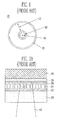
- FIG. I is a plan view of a conventional ultra-small optical/magnetic disk.
- the conventional ultra-small optical disk 10 includes an information recording zone 12 formed on a polycarbonate substrate, a metal hub 14 for supporting a spindle motor, and a center hole 16.
- a disk rim 18 having a width of 0.5 ⁇ 1.0 mm is formed at the outermost periphery of the optical disk 10.
- FIGS. 2A and 2B illustrate a structure of an optical disk having a phase-change medium as a recording layer, taken along a direction of a head of the optical disk.
- FIG. 2A is when the recording/reproducing head is opposite to the recording layer
- FIG. 2B is when the recording/reproducing head is in the same side as the recording layer.
- a laser beam 40 passes through a polycarbonate layer 20 and a first dielectric layer 22 to record a predetermined pattern on the recording layer 24 or read the recorded pattern. Then, the laser beam 40 passes through a second dielectric layer 26, but cannot pass through a reflective layer 28.
- a passivation layer 30 is formed on the reflective layer 28.
- phase-change optical disk The most important thing in initializing the phase-change optical disk is that it may be possible to generate degradation of the polycarbonate substrate very sensitive to heat during an initial crystallization process, and an initialization time should be shorter in order to increase productivity of the disk.
- the polycarbonate substrate is deformed at about 130 °C. Therefore, it is impossible to use a constant temperature furnace in order to initialize the phase-change optical disk.
- a conventional method of initializing a phase-change medium are disclosed in Korean Patent Laid-open Publication No. 2004-75705, published on August 30, 2004, entitled “Method of initializing optical recording medium", Korean Patent Laid-open Publication No. 2001-6496, published on January 26, 2001, entitled “Method of manufacturing optical information recording medium and optical information recording medium manufactured using the same", US Patent No. 6,335,069, issued on January 1, 2002, entitled “Phase-changeable optical recording medium, method of manufacturing the same, and method of recording information on the same", and so on.
- a conventional method of initializing a phase-change medium will be described with reference to the conventional arts disclosed in the Patents.
- a typical method of initializing a phase-change medium in the conventional arts uses a high-output laser having a long wavelength of about 800 nm, and irradiates the laser on an area of several ⁇ m 2 using a head including a low aperture lens to repeatedly scan a plurality of tracks at a time while rotating a disk at a high speed, thereby uniformly initializing the entire medium.
- the track includes a land and a groove.
- an initialization apparatus is very expensive, and in the case of initializing a 5-inch disk, it takes an average time of about 1 minute.
- the crystallization promotion layer is formed of a material having a melting point lower than that of the recording layer and a small difference between lattice constants of a crystalline phase of the recording layer and the additional layer to be easily formed as the crystalline phase on deposition of the recording layer.
- the crystallization promotion layer is formed of Sb, or SbTe-based alloy, Bi, or an alloy containing Bi.
- the method does not requires an initialization apparatus and an initialization time, it may be possible to generate degradation of disk characteristics due to inter-diffusion between a phase-change promotion layer and the recording layer by repeating recording and reproducing operations.
- Another method is to increase a deposition temperature higher than the atmospheric temperature using a method of crystallizing the recording layer simultaneously with the deposition, without using the phase-change promotion layer.
- the recording layer has a crystallization temperature of about 150 °C and the method uses kinetic energy of particles on deposition at a temperature lower than the crystallization temperature, thereby enabling the crystallization.
- the method has a problem that the substrate may be deformed due to deterioration of the substrate when polycarbonate is used as the optical disk substrate.
- Other initialization methods are to use a transparent laser having a wavelength not more than 400 nm in order to improve irregular initialization during an initialization process, and so on.
- the present invention is directed to an apparatus and method of initializing a phase-change optical disk using a UV lamp on initialization of a recording layer.
- the present invention is also directed to a method of initializing a large-sized area of an entire optical disk at a time using an initialization chamber having a UV lamp assembly.
- One aspect of the present invention is to provide an apparatus for initializing a phase-change optical disk including: a UV lamp emitting a UV beam to an optical disk having a phase-change medium as a recording layer for a predetermined time to initialize the recording layer; and a controller supplying a power source to the UV lamp.
- the phase-change optical disk initialization apparatus further includes a chamber supporting the UV lamp and connected to the controller.
- the chamber may have an inner wall coated with one of metal and oxide having a large reflectivity.
- the metal may include at least one of Au, Cr, and Ni, and the oxide may include at least one of aluminum oxide and zirconium oxide.
- the chamber may include a rotary plate for mounting the optical disk.
- the chamber may be formed to maintain a distance between the UV lamp and the rotary plate by 5 ⁇ 30 mm, and to rotate the rotary plate at 60 ⁇ 600 rpm.
- the UV lamp may have a diameter of 5 ⁇ 20 mm, and emit a UV beam having a wavelength of 400 nm by 10 ⁇ 100 %.
- the UV lamp may include a UV lamp assembly having a plurality of lamps with at least one of a circular ring shape and a cylindrical rod shape.
- a diameter of the lamps may become larger as the lamp goes from a center to a periphery of the chamber, and a distance between the UV lamps may be maintained by a predetermined interval.
- the diameter of an innermost UV lamp of the circular ring shaped lamp assembly is 20 ⁇ 30 mm, and the diameter of an outermost UV lamp is 120 ⁇ 150 mm.
- an interval between the lamps of the cylindrical rod shaped lamp assembly is 5 ⁇ 20 mm, a length of the lamp is 120 ⁇ 150 mm, and the lamps are connected to the controller in parallel.
- controller may further include a pulse regulator for applying a shock wave to the UV lamp while a low power UV beam is emitted to the optical disk for a predetermined time.
- Another aspect of the present invention is to provide a method of initializing a phase-change optical disk including: locating an optical disk in a UV beam effective region of a UV lamp in order to initialize the optical disk having a phase-change medium as a recording layer; and emitting the UV beam from the UV lamp for a predetermined time to initialize the recording layer.
- emitting the UV beam for a predetermined time includes controlling an output of the UV lamp within 50 ⁇ 1000 mW/10cm, while maintaining a substrate of the optical disk at a temperature of not more than 100 °C.
- the method may further include applying a shock wave to the recording layer while a low power UV beam is emitted from the UV lamp for a predetermined time.
- the method may further include rotating the optical disk while a UV beam is emitted from the UV lamp for a predetermined time.
- the phase-change medium may include a medium having a main component made of at least one selected from a group consisting of Ge, Sb, Te, In, Sn and Ga, and an additive made of at least one of Ag and Bi.
- the phase-change medium may include one selected from a GeSbTe-based alloy and an AgInSbTe-based alloy.
- FIG. I is a plan view of a conventional optical disk for storing optical information
- FIGS. 2A and 2B are cross-sectional views of an optical disk taken along the direction of a laser beam for recording and reproducing information
- FIGS. 3A and 3B are flow charts illustrating a method of initializing an optical disk in accordance with an exemplary embodiment of the present invention
- FIG. 4 is a schematic cross-sectional view of an apparatus for initializing an optical disk in accordance with an exemplary embodiment of the present invention
- FIGS. 5A and 5B are views illustrating arrangement of a UV lamp adaptable to an apparatus of initializing an optical disk in accordance with an exemplary embodiment of the present invention.
- FIGS. 6 and 7 show an XRD analysis result obtained after an initialization test of an optical disk having a GeSbTe-based alloy as a recording layer using an apparatus and method of initializing an optical disk in accordance with an exemplary embodiment of the present invention.
- FIGS. 3A and 3B are flow charts illustrating a method of initializing an optical disk in accordance with an exemplary embodiment of the present invention.
- the method of initializing a phase-change optical disk includes locating an optical disk in a UV beam effective region of a UV lamp (S10), and emitting the UV beam from the UV lamp for a predetermined time to crystallize an amorphous recording layer of the phase-change optical disk (S20).
- emitting the UV beam for a predetermined time includes controlling an output of the UV lamp within 50 ⁇ 1000 mW/10cm in order to maintain a substrate of the optical disk at a temperature of not more than 100 °C.
- the method of initializing a phase-change optical disk may include applying a shock wave to the amorphous recording layer while UV beam is emitted from the UV lamp at a low power for a predetermined time (S22), as shown in FIG 3B.
- the shock wave includes a high power pulse of 1 ⁇ 10 times.
- the method of initializing a phase-change optical disk may further include rotating the optical disk while UV beam is emitted from the UV lamp for a predetermined time (S30), as shown in FIGS 3A and 3B. Then, a certain intensity of UV beam and a high power pulse are more uniformly transmitted to the amorphous recording layer.
- phase-change optical disk it is possible to prevent a polycarbonate substrate from deteriorating when the amorphous recording layer of the phase-change optical disk is crystallized by a certain intensity of UV beam and a high power pulse of the UV lamp.
- a large-area of phase-change optical disk is initialized within a short time.
- the phase-change medium is formed of an alloy including a chalcogenide-based element having excellent characteristics as a phase-change medium.
- the phase-change medium includes a medium having a main component made of at least one selected from a group consisting of Ge, Sb, Te, In, Sn, Ga and so on, and additives made of at least one element selected from Ag, Bi and so on.
- the phase-change medium is referred to as an optical disk using a GeSbTe-based alloy or an AgInSbTe-based alloy as a phase-change medium.
- the present invention is focused in that beam in the UV wavelength range performs a core function in crystallization of the recording layer deposited as an amorphous structure by a sputtering method, which may be defined as photo-assisted crystallization. It is distinguished from crystallization by a conventional laser heating process. In other words, a thermal state required to crystallize the amorphous structure of the phase-change recording layer is slightly different depending on an amorphous state and material, but generally is at a temperature of 50 % of a melting point. Therefore, as described above, in the case of the photo-assisted crystallization by the UV beam, while heat is generated by the UV lamp, a process temperature can be adjusted not more than 100 °C.
- the UV beam affects a combined state between amorphous recording material particles to induce crystallization.
- the method of initializing a phase-change optical disk for example, using a UV lamp, in accordance with a first embodiment of the present invention crystallizes the optical disk by maintaining the UV lamp within a constant intensity range for a short time of about 10 seconds, or applying a pulse of 1 ⁇ 10 times during irradiation of a low power pulse of the UV lamp.
- FIG. 4 is a schematic cross-sectional view of an apparatus for initializing an optical disk in accordance with an exemplary embodiment of the present invention.
- the apparatus 100 for initializing a phase-change optical disk includes a UV lamp 110, a chamber 130 and a controller 140 in order to initialize an amorphous recording layer of an optical disk having a phase-change medium as a recording layer.
- the UV lamp 110 preferably has a diameter of about 5 ⁇ 20 mm, and emits a UV beam of 400 nm by 10 ⁇ 100%.
- the UV lamp 110 includes a plurality of lamps forming a UV lamp array, and may be fixedly supported in the chamber 130.
- the chamber 130 appropriately supports the UV lamp 110 therein to locate a phase-change optical disk 200 in a UV beam effective region 120 of the UV lamp 110.
- the UV lamps 110 are arranged on the optical disk 200 using a phase-change material spaced apart form each other by a predetermined interval.
- the chamber 130 includes a rotary plate 132 for mounting the phase-change optical disk 200.
- the rotary plate 132 rotates the phase-change optical disk 200 mounted on its surface.
- the chamber 130 includes a rounded inner wall 134 coated with gold to reflect the UV beam emitted from the UV lamp 110 toward the phase-change optical disk 200 mounted on the rotary plate 132.
- a material coated on the inner wall 134 may use a metal such as Cr, Ni and so on, or oxide such as aluminum oxide, zirconium oxide and so on, in addition to Au, having a large reflectivity
- the UV lamp 110 employed in the present invention has a diameter of 5 ⁇ 20 mm, and emits a UV beam having a wavelength of 400 nm by 10 ⁇ 100 %.
- a distance between the UV lamp 110 and the rotary plate 132 maintains a distance of 5 ⁇ 30 mm.
- the controller 140 is connected to the chamber 130 and the UV lamp 110 through a conducting wire 150 such as an electric wire. Basically, the controller 140 supplies a power source to the UV lamp 110.
- the controller 140 may include a predetermined power source for maintaining an output of the UV lamp 110 within a range of 50 ⁇ 1000 mW/10 cm.
- the controller 140 may include a pulse regulator 142 for applying a shock wave such as a pulse to the optical disk 200 during low power irradiation of the UV lamp 110.
- the initialization apparatus in accordance with the present invention may initialize the phase-change optical disk 200 by using a certain intensity of UV beam or applying a high power pulse during low power UV beam irradiation. That is, the controller 140 may include a power source and a pulse regulator to maintain a temperature of a substrate of the optical disk 200 not more than 100 °C to prevent the substrate of the optical disk 200 from deteriorating while initializing the optical disk 200.
- the present invention provides an initialization apparatus utilizing the UV lamp for initial crystallization of the recording layer of the optical disk.
- an operating time of the UV lamp is short and its power is maintained at a low state, a temperature of the optical disk is increased a little, and since it takes a time shorter than 10 seconds to initialize the optical disk, it is possible to remarkably reduce the initialization time.
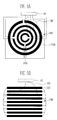
- FIGS. 5A and 5B are views illustrating arrangement of a UV lamp adaptable to an apparatus and method of initializing an optical disk in accordance with an exemplary embodiment of the present invention.
- FIG. 5A illustrates a UV lamp assembly employing a circular ring shaped UV lamp.
- a diameter of the UV lamp becomes larger as it goes from the innermost UV lamp 110a to the outermost UV lamp 110b.
- An interval between the lamps may be maintained by 5 ⁇ 20 mm.
- the innermost UV lamp 110a has a diameter of 20 ⁇ 30 mm
- the outermost UV lamp 110b has a diameter of 120 ⁇ 150 mm.
- the UV lamp assembly 160 is connected to the controller 140 including the power source and the pulse regulator through the conducting wire 150 such as a power supply wire and so on.
- FIG. 5B illustrates a UV lamp assembly employing a cylindrical rod shaped UV lamp.
- an interval between the UV lamps is 5 ⁇ 20 mm, and each lamp has a length of 120 ⁇ 150 mm.
- the UV lamp has a diameter of 5 ⁇ 20 mm.
- an initialization method of the phase-change recording layer by UV beam may be performed using the UV lamp assembly through the following two methods.
- RF power of the UV lamp is regulated within 50 ⁇ 1000 nm/10 cm (length of the lamp).
- the RF power is appropriately determined under a condition that a temperature is not more than 100 °C when a UV beam is irradiated from the UV lamp located at 1 cm over the substrate or the rotary plate for mounting the optical disk.
- 1 ⁇ 10 times of high power pulse is instantly applied by the pulse regulator to facilitate initialization of the recording layer during an operation time of 5 ⁇ 20 seconds of the lamp.
- FIGS. 6 and 7 show an XRD analysis result obtained after an initialization test of an optical disk having a GeSbTe-based alloy as a recording layer using an apparatus and method of initializing an optical disk in accordance with an exemplary embodiment of the present invention.
- FIG. 6 is a result, which is obtained through an XRD analysis, of variations of a crystalline structure depending on UV pulse power (5 times per 10 seconds) after lifting up the phase-change material GeSbTe (2:2:5) on the polycarbonate substrate by 20 nm.
- a pulse power (D) of 500 V relatively lower than a pulse power (B, C) of 1500 V or 1000 V.
- a graph A represents when a UV beam is not used.
- FIG. 7 shows a result obtained through an XRD analysis after depositing a thin layer in a structure of a conventional phase-change disk.
- crystallization (GeSbTe (200) peak around XRD 2 theta 30 degrees) of the recording layer is progressed at a lower pulse power (500 V, B) even in the phase-change optical disk structure of ZnS-SiO2 190 nm/GeSbTe 16 nm/ZnS-SiO2 25 nm/Al 100 nm/polycarbonate substrate.
- a graph A represents when a UV beam is not used.
- the present invention is capable of obtaining the following effects.
- the UV beam initialization apparatus in accordance with the present invention can reduce the apparatus manufacturing cost by about 90 % or more.
Landscapes
- Engineering & Computer Science (AREA)
- Manufacturing & Machinery (AREA)
- Chemical & Material Sciences (AREA)
- Inorganic Chemistry (AREA)
- Manufacturing Optical Record Carriers (AREA)
- Optical Recording Or Reproduction (AREA)
- Optical Record Carriers And Manufacture Thereof (AREA)
- Thermal Transfer Or Thermal Recording In General (AREA)
- Optical Head (AREA)
Abstract
Description
- This application claims priority to and the benefit of Korean Patent Application No. 2004-103666, filed December 09, 2004, the disclosure of which is incorporated herein by reference in its entirety.
- The present invention relates to an apparatus and method of initializing a phase-change optical disk capable of repeatedly recording information, and more particularly, to an apparatus and method of initializing an optical disk which uses a UV lamp in order to crystallize a phase-change recording layer.
- In general, in manufacturing an optical disk using a phase-change medium, initial crystallization means to make the phase-change medium into a zero-base. The optical disk can be recorded by instantly melting and rapidly quenching the disk using a laser beam to form an amorphous mark.
- FIG. I is a plan view of a conventional ultra-small optical/magnetic disk. As shown in FIG. 1, the conventional ultra-small
optical disk 10 includes aninformation recording zone 12 formed on a polycarbonate substrate, ametal hub 14 for supporting a spindle motor, and acenter hole 16. Adisk rim 18 having a width of 0.5 ~ 1.0 mm is formed at the outermost periphery of theoptical disk 10. A process of writing or reading information on or from the ultra-smalloptical disk 10 will be described as follows. - FIGS. 2A and 2B illustrate a structure of an optical disk having a phase-change medium as a recording layer, taken along a direction of a head of the optical disk. FIG. 2A is when the recording/reproducing head is opposite to the recording layer, and FIG. 2B is when the recording/reproducing head is in the same side as the recording layer. In the two cases, a
laser beam 40 passes through apolycarbonate layer 20 and a firstdielectric layer 22 to record a predetermined pattern on therecording layer 24 or read the recorded pattern. Then, thelaser beam 40 passes through a seconddielectric layer 26, but cannot pass through areflective layer 28. Apassivation layer 30 is formed on thereflective layer 28. - The most important thing in initializing the phase-change optical disk is that it may be possible to generate degradation of the polycarbonate substrate very sensitive to heat during an initial crystallization process, and an initialization time should be shorter in order to increase productivity of the disk. The polycarbonate substrate is deformed at about 130 °C. Therefore, it is impossible to use a constant temperature furnace in order to initialize the phase-change optical disk.
- A conventional method of initializing a phase-change medium are disclosed in Korean Patent Laid-open Publication No. 2004-75705, published on August 30, 2004, entitled "Method of initializing optical recording medium", Korean Patent Laid-open Publication No. 2001-6496, published on January 26, 2001, entitled "Method of manufacturing optical information recording medium and optical information recording medium manufactured using the same", US Patent No. 6,335,069, issued on January 1, 2002, entitled "Phase-changeable optical recording medium, method of manufacturing the same, and method of recording information on the same", and so on. A conventional method of initializing a phase-change medium will be described with reference to the conventional arts disclosed in the Patents.
- First, a typical method of initializing a phase-change medium in the conventional arts uses a high-output laser having a long wavelength of about 800 nm, and irradiates the laser on an area of several µm2 using a head including a low aperture lens to repeatedly scan a plurality of tracks at a time while rotating a disk at a high speed, thereby uniformly initializing the entire medium. The track includes a land and a groove. In this case, an initialization apparatus is very expensive, and in the case of initializing a 5-inch disk, it takes an average time of about 1 minute.
- Next, among technologies on initialization of the phase-change medium, there are two methods using a method of manufacturing a medium not requiring initialization. One method is to form a crystallization promotion layer before deposition of the recording layer. The crystallization promotion layer, referred to as "an additional layer", is made of a material having a melting point lower than that of the recording layer and a small difference between lattice constants of a crystalline phase of the recording layer and the additional layer to be easily formed as the crystalline phase on deposition of the recording layer. The crystallization promotion layer is formed of Sb, or SbTe-based alloy, Bi, or an alloy containing Bi. While the method does not requires an initialization apparatus and an initialization time, it may be possible to generate degradation of disk characteristics due to inter-diffusion between a phase-change promotion layer and the recording layer by repeating recording and reproducing operations. Another method is to increase a deposition temperature higher than the atmospheric temperature using a method of crystallizing the recording layer simultaneously with the deposition, without using the phase-change promotion layer. The recording layer has a crystallization temperature of about 150 °C and the method uses kinetic energy of particles on deposition at a temperature lower than the crystallization temperature, thereby enabling the crystallization. However, the method has a problem that the substrate may be deformed due to deterioration of the substrate when polycarbonate is used as the optical disk substrate.
- Other initialization methods are to use a transparent laser having a wavelength not more than 400 nm in order to improve irregular initialization during an initialization process, and so on.
- The present invention is directed to an apparatus and method of initializing a phase-change optical disk using a UV lamp on initialization of a recording layer.
- The present invention is also directed to a method of initializing a large-sized area of an entire optical disk at a time using an initialization chamber having a UV lamp assembly.
- One aspect of the present invention is to provide an apparatus for initializing a phase-change optical disk including: a UV lamp emitting a UV beam to an optical disk having a phase-change medium as a recording layer for a predetermined time to initialize the recording layer; and a controller supplying a power source to the UV lamp.
- Preferably, the phase-change optical disk initialization apparatus further includes a chamber supporting the UV lamp and connected to the controller.
- In addition, the chamber may have an inner wall coated with one of metal and oxide having a large reflectivity. The metal may include at least one of Au, Cr, and Ni, and the oxide may include at least one of aluminum oxide and zirconium oxide.
- Further, the chamber may include a rotary plate for mounting the optical disk.
- In addition, the chamber may be formed to maintain a distance between the UV lamp and the rotary plate by 5 ~ 30 mm, and to rotate the rotary plate at 60 ~ 600 rpm.
- Further, the UV lamp may have a diameter of 5 ~ 20 mm, and emit a UV beam having a wavelength of 400 nm by 10 ~ 100 %.
- In addition, the UV lamp may include a UV lamp assembly having a plurality of lamps with at least one of a circular ring shape and a cylindrical rod shape. In the circular ring shaped lamp assembly, a diameter of the lamps may become larger as the lamp goes from a center to a periphery of the chamber, and a distance between the UV lamps may be maintained by a predetermined interval. At this time, preferably, the diameter of an innermost UV lamp of the circular ring shaped lamp assembly is 20 ~ 30 mm, and the diameter of an outermost UV lamp is 120 ~ 150 mm. In addition, preferably, an interval between the lamps of the cylindrical rod shaped lamp assembly is 5 ~ 20 mm, a length of the lamp is 120 ~ 150 mm, and the lamps are connected to the controller in parallel.
- In addition, the controller may further include a pulse regulator for applying a shock wave to the UV lamp while a low power UV beam is emitted to the optical disk for a predetermined time.
- Another aspect of the present invention is to provide a method of initializing a phase-change optical disk including: locating an optical disk in a UV beam effective region of a UV lamp in order to initialize the optical disk having a phase-change medium as a recording layer; and emitting the UV beam from the UV lamp for a predetermined time to initialize the recording layer.
- Preferably, emitting the UV beam for a predetermined time includes controlling an output of the UV lamp within 50 ~ 1000 mW/10cm, while maintaining a substrate of the optical disk at a temperature of not more than 100 °C.
- In addition, the method may further include applying a shock wave to the recording layer while a low power UV beam is emitted from the UV lamp for a predetermined time.
- In addition, the method may further include rotating the optical disk while a UV beam is emitted from the UV lamp for a predetermined time.
- Further, the phase-change medium may include a medium having a main component made of at least one selected from a group consisting of Ge, Sb, Te, In, Sn and Ga, and an additive made of at least one of Ag and Bi. For example, the phase-change medium may include one selected from a GeSbTe-based alloy and an AgInSbTe-based alloy.
- The above and other features and advantages of the present invention will become more apparent to those of ordinary skill in the art by describing in detail exemplary embodiments thereof with reference to the attached drawings in which:
- FIG. I is a plan view of a conventional optical disk for storing optical information;
- FIGS. 2A and 2B are cross-sectional views of an optical disk taken along the direction of a laser beam for recording and reproducing information;
- FIGS. 3A and 3B are flow charts illustrating a method of initializing an optical disk in accordance with an exemplary embodiment of the present invention;
- FIG. 4 is a schematic cross-sectional view of an apparatus for initializing an optical disk in accordance with an exemplary embodiment of the present invention;
- FIGS. 5A and 5B are views illustrating arrangement of a UV lamp adaptable to an apparatus of initializing an optical disk in accordance with an exemplary embodiment of the present invention; and
- FIGS. 6 and 7 show an XRD analysis result obtained after an initialization test of an optical disk having a GeSbTe-based alloy as a recording layer using an apparatus and method of initializing an optical disk in accordance with an exemplary embodiment of the present invention.
- The present invention will now be described more fully hereinafter with reference to the accompanying drawings, in which preferred embodiments of the invention are shown. This invention may, however, be embodied in different forms and should not be construed as limited to the embodiments set forth herein. Rather, these embodiments are provided so that this disclosure will be thorough and complete, and will fully convey the scope of the invention to those skilled in the art.
- FIGS. 3A and 3B are flow charts illustrating a method of initializing an optical disk in accordance with an exemplary embodiment of the present invention.
- Referring to FIG. 3A, the method of initializing a phase-change optical disk includes locating an optical disk in a UV beam effective region of a UV lamp (S10), and emitting the UV beam from the UV lamp for a predetermined time to crystallize an amorphous recording layer of the phase-change optical disk (S20).
- At this time, emitting the UV beam for a predetermined time includes controlling an output of the UV lamp within 50 ~ 1000 mW/10cm in order to maintain a substrate of the optical disk at a temperature of not more than 100 °C.
- The method of initializing a phase-change optical disk may include applying a shock wave to the amorphous recording layer while UV beam is emitted from the UV lamp at a low power for a predetermined time (S22), as shown in FIG 3B. The shock wave includes a high power pulse of 1 ~ 10 times.
- In addition, the method of initializing a phase-change optical disk may further include rotating the optical disk while UV beam is emitted from the UV lamp for a predetermined time (S30), as shown in FIGS 3A and 3B. Then, a certain intensity of UV beam and a high power pulse are more uniformly transmitted to the amorphous recording layer.
- In accordance with the constitution described above, it is possible to prevent a polycarbonate substrate from deteriorating when the amorphous recording layer of the phase-change optical disk is crystallized by a certain intensity of UV beam and a high power pulse of the UV lamp. In addition, a large-area of phase-change optical disk is initialized within a short time.
- Meanwhile, the phase-change medium is formed of an alloy including a chalcogenide-based element having excellent characteristics as a phase-change medium. In addition, the phase-change medium includes a medium having a main component made of at least one selected from a group consisting of Ge, Sb, Te, In, Sn, Ga and so on, and additives made of at least one element selected from Ag, Bi and so on. For example, the phase-change medium is referred to as an optical disk using a GeSbTe-based alloy or an AgInSbTe-based alloy as a phase-change medium.
- As described above, the present invention is focused in that beam in the UV wavelength range performs a core function in crystallization of the recording layer deposited as an amorphous structure by a sputtering method, which may be defined as photo-assisted crystallization. It is distinguished from crystallization by a conventional laser heating process. In other words, a thermal state required to crystallize the amorphous structure of the phase-change recording layer is slightly different depending on an amorphous state and material, but generally is at a temperature of 50 % of a melting point. Therefore, as described above, in the case of the photo-assisted crystallization by the UV beam, while heat is generated by the UV lamp, a process temperature can be adjusted not more than 100 °C. In addition, the UV beam affects a combined state between amorphous recording material particles to induce crystallization. As described above, the method of initializing a phase-change optical disk, for example, using a UV lamp, in accordance with a first embodiment of the present invention crystallizes the optical disk by maintaining the UV lamp within a constant intensity range for a short time of about 10 seconds, or applying a pulse of 1 ~ 10 times during irradiation of a low power pulse of the UV lamp.
- FIG. 4 is a schematic cross-sectional view of an apparatus for initializing an optical disk in accordance with an exemplary embodiment of the present invention.
- Referring to FIG. 4, the
apparatus 100 for initializing a phase-change optical disk includes aUV lamp 110, achamber 130 and acontroller 140 in order to initialize an amorphous recording layer of an optical disk having a phase-change medium as a recording layer. - Specifically, the
UV lamp 110 preferably has a diameter of about 5 ~ 20 mm, and emits a UV beam of 400 nm by 10 ~ 100%. TheUV lamp 110 includes a plurality of lamps forming a UV lamp array, and may be fixedly supported in thechamber 130. - The
chamber 130 appropriately supports theUV lamp 110 therein to locate a phase-changeoptical disk 200 in a UV beameffective region 120 of theUV lamp 110. As a result, theUV lamps 110 are arranged on theoptical disk 200 using a phase-change material spaced apart form each other by a predetermined interval. - In addition, the
chamber 130 includes arotary plate 132 for mounting the phase-changeoptical disk 200. Therotary plate 132 rotates the phase-changeoptical disk 200 mounted on its surface. In addition, thechamber 130 includes a roundedinner wall 134 coated with gold to reflect the UV beam emitted from theUV lamp 110 toward the phase-changeoptical disk 200 mounted on therotary plate 132. A material coated on theinner wall 134 may use a metal such as Cr, Ni and so on, or oxide such as aluminum oxide, zirconium oxide and so on, in addition to Au, having a large reflectivity - Meanwhile, in order to uniformly initialize the recording layer in the
optical disk 200, it is very important to locate theoptical disk 200 within an appropriate distance (UV beam effective region 120) from the UV lamp. Therefore, when theoptical disk 200 has a diameter of 25 ~ 150 mm, theUV lamp 110 employed in the present invention has a diameter of 5 ~ 20 mm, and emits a UV beam having a wavelength of 400 nm by 10 ~ 100 %. Preferably, a distance between theUV lamp 110 and therotary plate 132 maintains a distance of 5 ~ 30 mm. In addition, in order to increase initialization uniformity, it is preferable to rotate therotary plate 132 at a speed of 60 ~ 600 rpm during UV irradiation. - The
controller 140 is connected to thechamber 130 and theUV lamp 110 through aconducting wire 150 such as an electric wire. Basically, thecontroller 140 supplies a power source to theUV lamp 110. For this, thecontroller 140 may include a predetermined power source for maintaining an output of theUV lamp 110 within a range of 50 ~ 1000 mW/10 cm. In addition, thecontroller 140 may include apulse regulator 142 for applying a shock wave such as a pulse to theoptical disk 200 during low power irradiation of theUV lamp 110. In this case, the initialization apparatus in accordance with the present invention may initialize the phase-changeoptical disk 200 by using a certain intensity of UV beam or applying a high power pulse during low power UV beam irradiation. That is, thecontroller 140 may include a power source and a pulse regulator to maintain a temperature of a substrate of theoptical disk 200 not more than 100 °C to prevent the substrate of theoptical disk 200 from deteriorating while initializing theoptical disk 200. - As described above, the present invention provides an initialization apparatus utilizing the UV lamp for initial crystallization of the recording layer of the optical disk. In accordance with the present invention, since an operating time of the UV lamp is short and its power is maintained at a low state, a temperature of the optical disk is increased a little, and since it takes a time shorter than 10 seconds to initialize the optical disk, it is possible to remarkably reduce the initialization time.
- FIGS. 5A and 5B are views illustrating arrangement of a UV lamp adaptable to an apparatus and method of initializing an optical disk in accordance with an exemplary embodiment of the present invention.
- FIG. 5A illustrates a UV lamp assembly employing a circular ring shaped UV lamp. Referring to FIG. 5A, a diameter of the UV lamp becomes larger as it goes from the
innermost UV lamp 110a to theoutermost UV lamp 110b. An interval between the lamps may be maintained by 5 ~ 20 mm. In consideration of the size of a current optical disk, theinnermost UV lamp 110a has a diameter of 20 ~ 30 mm, and theoutermost UV lamp 110b has a diameter of 120 ~ 150 mm. In addition, theUV lamp assembly 160 is connected to thecontroller 140 including the power source and the pulse regulator through theconducting wire 150 such as a power supply wire and so on. - FIG. 5B illustrates a UV lamp assembly employing a cylindrical rod shaped UV lamp. Referring to FIG. 5B, an interval between the UV lamps is 5 ~ 20 mm, and each lamp has a length of 120 ~ 150 mm. At this time, the UV lamp has a diameter of 5 ~ 20 mm.
- As described above, an initialization method of the phase-change recording layer by UV beam may be performed using the UV lamp assembly through the following two methods.
- First, there is a method of initializing an amorphous recording layer by irradiating UV beam with a constant wave. In this method, RF power of the UV lamp is regulated within 50 ~ 1000 nm/10 cm (length of the lamp). The RF power is appropriately determined under a condition that a temperature is not more than 100 °C when a UV beam is irradiated from the UV lamp located at 1 cm over the substrate or the rotary plate for mounting the optical disk.
- Second, there is another method of applying about 5 times of pulses during low power irradiation. For example, 1 ~ 10 times of high power pulse is instantly applied by the pulse regulator to facilitate initialization of the recording layer during an operation time of 5 ~ 20 seconds of the lamp. Energy generated by the lamp may be represented as 1/2(CV2) per unit area (V=voltage, C=capacitance). When C is 100 x 10-6 at a voltage of 1000 V, an energy of about 50 J can be instantly generated.
- FIGS. 6 and 7 show an XRD analysis result obtained after an initialization test of an optical disk having a GeSbTe-based alloy as a recording layer using an apparatus and method of initializing an optical disk in accordance with an exemplary embodiment of the present invention.
- FIG. 6 is a result, which is obtained through an XRD analysis, of variations of a crystalline structure depending on UV pulse power (5 times per 10 seconds) after lifting up the phase-change material GeSbTe (2:2:5) on the polycarbonate substrate by 20 nm. Referring to FIG. 6, it is appreciated that crystallization of the recording layer is generated even at a pulse power (D) of 500 V relatively lower than a pulse power (B, C) of 1500 V or 1000 V. In this process, a graph A represents when a UV beam is not used.
- FIG. 7 shows a result obtained through an XRD analysis after depositing a thin layer in a structure of a conventional phase-change disk. Referring to FIG. 7, it is appreciated that crystallization (GeSbTe (200) peak around
XRD 2theta 30 degrees) of the recording layer is progressed at a lower pulse power (500 V, B) even in the phase-change optical disk structure of ZnS-SiO2 190 nm/GeSbTe 16 nm/ZnS-SiO2 25 nm/Al 100 nm/polycarbonate substrate. In this process, a graph A represents when a UV beam is not used. - As can be seen from the foregoing, the present invention is capable of obtaining the following effects.
- First, it is possible to improve productivity by initializing a large area of an optical disk surface using a UV lamp at a time to remarkably reduce an initialization time within 10 seconds.
- Second, considering that an initialization apparatus using a conventional laser head is very expensive, the UV beam initialization apparatus in accordance with the present invention can reduce the apparatus manufacturing cost by about 90 % or more.
- Third, it is possible to improve initialization uniformity through a method of initializing a large area of a disk surface at a time.
- Fourth, it is possible to increase quality competitive power since a source of unnecessary contamination and defect is basically blocked by an initialization process.
- Although the present invention has been described with reference to certain exemplary embodiments thereof, it will be understood by those skilled in the art that a variety of modifications and variations may be made to the present invention without departing from the spirit or scope of the present invention defined in the appended claims, and their equivalents.
Claims (21)
- An apparatus for initializing a phase-change optical disk, comprising:a UV lamp emitting a UV beam to an optical disk having a phase-change medium as a recording layer for a predetermined time to initialize the recording layer; anda controller supplying a power source to the UV lamp.
- The apparatus for initializing a phase-change optical disk according to claim 1, further comprising a chamber supporting the UV lamp and connected to the controller.
- The apparatus for initializing a phase-change optical disk according to claim 2, wherein the chamber has an inner wall coated with one of metal and oxide having a large reflectivity.
- The apparatus for initializing a phase-change optical disk according to claim 3, wherein the metal comprises at least one of Au, Cr, and Ni, and the oxide comprises at least one of aluminum oxide and zirconium oxide.
- The apparatus for initializing a phase-change optical disk according to claim 2, wherein the chamber comprises a rotary plate for mounting the optical disk.
- The apparatus for initializing a phase-change optical disk according to claim 5, wherein the chamber is formed to maintain a distance between the UV lamp and the rotary plate by 5 ~ 30 mm, and to rotate the rotary plate at 60 ~ 600 rpm.
- The apparatus for initializing a phase-change optical disk according to claim 2, wherein the UV lamp has a diameter of 5 ~ 20 mm, and emits the UV beam having a wavelength of 400 nm by 10 ~ 100 %.
- The apparatus for initializing a phase-change optical disk according to claim 7, wherein the UV lamp comprises a UV lamp assembly having a plurality of lamps with at least one shape of a circular ring shape and a cylindrical rod shape.
- The apparatus for initializing a phase-change optical disk according to claim 8, wherein the circular ring shaped lamp assembly has a diameter becoming larger as the lamp goes from a center to a periphery of the chamber, and a distance between the UV lamps maintained by a predetermined interval.
- The apparatus for initializing a phase-change optical disk according to claim 9, wherein the diameter of an innermost UV lamp of the circular ring shaped lamp assembly is 20 ~ 30 mm, and the diameter of an outermost UV lamp is 120 ~ 150 mm.
- The apparatus for initializing a phase-change optical disk according to claim 8, wherein an interval between the lamps of the cylindrical rod shaped lamp assembly is 5 ~ 20 mm, a length of each lamp is 120 ~ 150 mm, and the lamps are connected to the controller in parallel.
- The apparatus for initializing a phase-change optical disk according to one of claims 1 to 11, wherein the controller controls an output of the UV lamp within 50 ~ 1000 mW/10cm while maintaining a substrate of the optical disk at a temperature of not more than 100 °C.
- The apparatus for initializing a phase-change optical disk according to one of claims 1 to 11, wherein the controller further comprises a pulse regulator for applying a shock wave to the UV lamp while the UV beam is emitted to the optical disk for a predetermined time.
- The apparatus for initializing a phase-change optical disk according to any one of claims 1 to 13, wherein the phase-change medium comprises a medium having a main component made of at least one selected from a group consisting of Ge, Sb, Te, In, Sn and Ga, and an additive made of at least one ofAg and Bi.
- The apparatus for initializing a phase-change optical disk according to any one of claims 1 to 13, wherein the phase-change medium comprises one selected from a GeSbTe-based alloy and an AgInSbTe-based alloy.
- A method of initializing a phase-change optical disk, comprising:locating an optical disk in a UV beam effective region of a UV lamp in order to initialize the optical disk having a phase-change medium as a recording layer; andemitting the UV beam from the UV lamp for a predetermined time to initialize the recording layer.
- The method of initializing a phase-change optical disk according to claim 16, wherein emitting the UV beam for a predetermined time comprises controlling an output of the UV lamp within 50 ~ 1000 mW/10cm while maintaining a substrate of the optical disk at a temperature of not more than 100 °C.
- The method of initializing a phase-change optical disk according to claim 16 or 17, further comprising applying a shock wave to the recording layer while a low power UV beam is emitted from the UV lamp for a predetermined time.
- The method of initializing a phase-change optical disk according to claim 16, 17 or 18, further comprising rotating the optical disk while a UV beam is emitted from the UV lamp for a predetermined time.
- The method of initializing a phase-change optical disk according to any one of claims 16 to 19, wherein the phase-change medium comprises a medium having a main component made of at least one selected from a group consisting of Ge, Sb, Te, In, Sn and Ga, and an additive made of at least one of Ag and Bi.
- The method of initializing a phase-change optical disk according to any one of claims 16 to 19, wherein the phase-change medium comprises one selected from a GeSbTe-based alloy and an AgInSbTe-based alloy.
Applications Claiming Priority (1)
| Application Number | Priority Date | Filing Date | Title |
|---|---|---|---|
| KR1020040103666A KR100698012B1 (en) | 2004-12-09 | 2004-12-09 | Initialization device and method of phase change optical disk |
Publications (3)
| Publication Number | Publication Date |
|---|---|
| EP1669990A2 true EP1669990A2 (en) | 2006-06-14 |
| EP1669990A3 EP1669990A3 (en) | 2007-08-08 |
| EP1669990B1 EP1669990B1 (en) | 2009-11-04 |
Family
ID=36206043
Family Applications (1)
| Application Number | Title | Priority Date | Filing Date |
|---|---|---|---|
| EP05111378A Expired - Lifetime EP1669990B1 (en) | 2004-12-09 | 2005-11-28 | Apparatus and method of initializing phase-change optical disk |
Country Status (8)
| Country | Link |
|---|---|
| US (1) | US7558187B2 (en) |
| EP (1) | EP1669990B1 (en) |
| JP (1) | JP4053565B2 (en) |
| KR (1) | KR100698012B1 (en) |
| CN (1) | CN100397498C (en) |
| AT (1) | ATE447757T1 (en) |
| DE (1) | DE602005017459D1 (en) |
| TW (1) | TWI328814B (en) |
Families Citing this family (3)
| Publication number | Priority date | Publication date | Assignee | Title |
|---|---|---|---|---|
| JP2008288508A (en) * | 2007-05-21 | 2008-11-27 | Shimadzu Corp | Crystallization apparatus and crystallization method |
| JP2008294186A (en) * | 2007-05-24 | 2008-12-04 | Shimadzu Corp | Crystallization apparatus and crystallization method |
| US8092416B2 (en) | 2008-03-28 | 2012-01-10 | Vitalmex Internacional S.A. De C.V. | Device and method for connecting a blood pump without trapping air bubbles |
Family Cites Families (21)
| Publication number | Priority date | Publication date | Assignee | Title |
|---|---|---|---|---|
| GB1581998A (en) * | 1977-09-27 | 1980-12-31 | Applied Photophysics Ltd | Ultraviolet curing systems |
| JPS6297885A (en) | 1985-10-25 | 1987-05-07 | Nippon Telegr & Teleph Corp <Ntt> | Laser beam recording member and production thereof |
| JP2502562B2 (en) * | 1987-02-17 | 1996-05-29 | 日立マクセル株式会社 | Optical disk protective film coating method |
| KR100264705B1 (en) * | 1989-01-11 | 2000-09-01 | 야스카와 히데아키 | Optical discs and methods of manufacturing the same |
| KR970006308B1 (en) | 1994-03-15 | 1997-04-25 | 대우전자 주식회사 | In/out interface of monitor screen controller |
| US5684778A (en) * | 1994-09-27 | 1997-11-04 | Matsushita Electric Industrial Co., Ltd. | Initialization process for a phase change recording medium with a zero level drop in flash light emission |
| EP0965984B1 (en) | 1997-02-28 | 2008-08-20 | Asahi Kasei Kabushiki Kaisha | Method of manufacturing a phase change recording medium, and method of recording information on the same |
| US6699637B2 (en) | 1997-04-16 | 2004-03-02 | Asahi Kasei Kabushiki Kaisha | Process for producing optical information recording medium and optical information recording medium produced by the process |
| GB2326246A (en) * | 1997-06-11 | 1998-12-16 | Timothy Michael William Fryer | Permeable reflecting mesh |
| JP2000113518A (en) * | 1998-10-06 | 2000-04-21 | Teijin Ltd | Method of manufacturing phase change optical disk |
| US6511788B1 (en) * | 1999-02-12 | 2003-01-28 | Sony Corporation | Multi-layered optical disc |
| DE60042477D1 (en) | 1999-07-12 | 2009-08-13 | Panasonic Corp | OPTICAL INFORMATION RECORDING MEDIUM AND METHOD FOR INITIALIZING THE SAME |
| US6587429B1 (en) | 1999-11-16 | 2003-07-01 | Polaroid Corporation | System and method for initializing phase change recording media |
| JP4104273B2 (en) | 2000-05-29 | 2008-06-18 | 株式会社リコー | Initial crystallization apparatus for information recording medium |
| JP2002092990A (en) * | 2000-09-19 | 2002-03-29 | Ricoh Co Ltd | Method for manufacturing optical information recording medium and optical information recording medium |
| TW565835B (en) | 2001-01-10 | 2003-12-11 | Ricoh Kk | Phase change optical recording medium |
| JP2003123326A (en) * | 2001-10-17 | 2003-04-25 | Ulvac Japan Ltd | Crystallization apparatus for recording film and crystallization method |
| TWI257096B (en) * | 2002-02-08 | 2006-06-21 | Sony Corp | Method for initializing optical recording medium |
| US20040081069A1 (en) * | 2002-10-17 | 2004-04-29 | Hitachi Maxell, Ltd. | Optical information-recording medium and method for producing the same |
| KR20040090667A (en) * | 2003-04-18 | 2004-10-26 | 삼성전기주식회사 | light unit for displaying |
| JP4238341B2 (en) * | 2003-04-23 | 2009-03-18 | 富士電機デバイステクノロジー株式会社 | Method and apparatus for manufacturing magnetic recording medium |
-
2004
- 2004-12-09 KR KR1020040103666A patent/KR100698012B1/en not_active Expired - Fee Related
-
2005
- 2005-11-28 EP EP05111378A patent/EP1669990B1/en not_active Expired - Lifetime
- 2005-11-28 AT AT05111378T patent/ATE447757T1/en not_active IP Right Cessation
- 2005-11-28 DE DE602005017459T patent/DE602005017459D1/en not_active Expired - Lifetime
- 2005-12-05 TW TW094142807A patent/TWI328814B/en not_active IP Right Cessation
- 2005-12-08 US US11/299,067 patent/US7558187B2/en not_active Expired - Fee Related
- 2005-12-08 JP JP2005355074A patent/JP4053565B2/en not_active Expired - Fee Related
- 2005-12-09 CN CNB2005101294840A patent/CN100397498C/en not_active Expired - Fee Related
Also Published As
| Publication number | Publication date |
|---|---|
| DE602005017459D1 (en) | 2009-12-17 |
| JP2006164506A (en) | 2006-06-22 |
| TW200638414A (en) | 2006-11-01 |
| CN100397498C (en) | 2008-06-25 |
| ATE447757T1 (en) | 2009-11-15 |
| TWI328814B (en) | 2010-08-11 |
| US7558187B2 (en) | 2009-07-07 |
| KR20060064969A (en) | 2006-06-14 |
| EP1669990A3 (en) | 2007-08-08 |
| EP1669990B1 (en) | 2009-11-04 |
| US20060087922A1 (en) | 2006-04-27 |
| KR100698012B1 (en) | 2007-03-23 |
| CN1815577A (en) | 2006-08-09 |
| JP4053565B2 (en) | 2008-02-27 |
Similar Documents
| Publication | Publication Date | Title |
|---|---|---|
| US6445669B1 (en) | Initialization of phase-change optical recording medium | |
| CN100426397C (en) | Information record mdeium, information recored method and information replay method | |
| CN1967688A (en) | Information recording medium and method for manufacturing the same | |
| US5861196A (en) | Laser texturing a glass or glass-ceramic substrate | |
| EP1669990B1 (en) | Apparatus and method of initializing phase-change optical disk | |
| US5897798A (en) | Laser texturing apparatus employing a rotating mirror | |
| JP4014942B2 (en) | Optical information recording medium, method for manufacturing the same, and initialization apparatus | |
| JP2003272172A (en) | Optical disk initialization method and initialization device | |
| JP2843539B2 (en) | Texture device and texture processing method | |
| JPH10134345A (en) | Magnetic recording medium and method of manufacturing the same | |
| US20030043723A1 (en) | Optical data storage medium | |
| JP2006252765A (en) | Phase change information recording medium | |
| JPH09231562A (en) | Magnetic recording medium and method of manufacturing the same | |
| JP2629717B2 (en) | Information recording medium | |
| JP4244090B2 (en) | Optical information recording medium | |
| JP2000090502A (en) | Phase change optical recording medium initialization apparatus and phase change optical recording medium | |
| JP4171461B2 (en) | Optical disc initialization apparatus and initialization method | |
| JP4452646B2 (en) | Manufacturing method and initialization apparatus for optical information recording medium | |
| JPH08287460A (en) | Method of manufacturing magnetic recording medium | |
| JP3886634B2 (en) | Method and apparatus for initializing information recording medium | |
| JP2000215531A (en) | Optical recording medium initialization method | |
| JPH1094886A (en) | Laser texture device | |
| US20090196157A1 (en) | Information recording medium | |
| JP2001043577A (en) | Information recording medium initialization method and initialization apparatus | |
| JP2005158211A (en) | Initialization method of phase change optical recording medium |
Legal Events
| Date | Code | Title | Description |
|---|---|---|---|
| PUAI | Public reference made under article 153(3) epc to a published international application that has entered the european phase |
Free format text: ORIGINAL CODE: 0009012 |
|
| AK | Designated contracting states |
Kind code of ref document: A2 Designated state(s): AT BE BG CH CY CZ DE DK EE ES FI FR GB GR HU IE IS IT LI LT LU LV MC NL PL PT RO SE SI SK TR |
|
| AX | Request for extension of the european patent |
Extension state: AL BA HR MK YU |
|
| PUAL | Search report despatched |
Free format text: ORIGINAL CODE: 0009013 |
|
| AK | Designated contracting states |
Kind code of ref document: A3 Designated state(s): AT BE BG CH CY CZ DE DK EE ES FI FR GB GR HU IE IS IT LI LT LU LV MC NL PL PT RO SE SI SK TR |
|
| AX | Request for extension of the european patent |
Extension state: AL BA HR MK YU |
|
| 17P | Request for examination filed |
Effective date: 20080108 |
|
| 17Q | First examination report despatched |
Effective date: 20080303 |
|
| AKX | Designation fees paid |
Designated state(s): AT BE BG CH CY CZ DE DK EE ES FI FR GB GR HU IE IS IT LI LT LU LV MC NL PL PT RO SE SI SK TR |
|
| GRAP | Despatch of communication of intention to grant a patent |
Free format text: ORIGINAL CODE: EPIDOSNIGR1 |
|
| GRAS | Grant fee paid |
Free format text: ORIGINAL CODE: EPIDOSNIGR3 |
|
| GRAA | (expected) grant |
Free format text: ORIGINAL CODE: 0009210 |
|
| AK | Designated contracting states |
Kind code of ref document: B1 Designated state(s): AT BE BG CH CY CZ DE DK EE ES FI FR GB GR HU IE IS IT LI LT LU LV MC NL PL PT RO SE SI SK TR |
|
| REG | Reference to a national code |
Ref country code: GB Ref legal event code: FG4D |
|
| REG | Reference to a national code |
Ref country code: CH Ref legal event code: EP |
|
| REG | Reference to a national code |
Ref country code: IE Ref legal event code: FG4D |
|
| REF | Corresponds to: |
Ref document number: 602005017459 Country of ref document: DE Date of ref document: 20091217 Kind code of ref document: P |
|
| NLV1 | Nl: lapsed or annulled due to failure to fulfill the requirements of art. 29p and 29m of the patents act | ||
| LTIE | Lt: invalidation of european patent or patent extension |
Effective date: 20091104 |
|
| PG25 | Lapsed in a contracting state [announced via postgrant information from national office to epo] |
Ref country code: FI Free format text: LAPSE BECAUSE OF FAILURE TO SUBMIT A TRANSLATION OF THE DESCRIPTION OR TO PAY THE FEE WITHIN THE PRESCRIBED TIME-LIMIT Effective date: 20091104 Ref country code: IS Free format text: LAPSE BECAUSE OF FAILURE TO SUBMIT A TRANSLATION OF THE DESCRIPTION OR TO PAY THE FEE WITHIN THE PRESCRIBED TIME-LIMIT Effective date: 20100304 Ref country code: SE Free format text: LAPSE BECAUSE OF FAILURE TO SUBMIT A TRANSLATION OF THE DESCRIPTION OR TO PAY THE FEE WITHIN THE PRESCRIBED TIME-LIMIT Effective date: 20091104 Ref country code: ES Free format text: LAPSE BECAUSE OF FAILURE TO SUBMIT A TRANSLATION OF THE DESCRIPTION OR TO PAY THE FEE WITHIN THE PRESCRIBED TIME-LIMIT Effective date: 20100215 Ref country code: LT Free format text: LAPSE BECAUSE OF FAILURE TO SUBMIT A TRANSLATION OF THE DESCRIPTION OR TO PAY THE FEE WITHIN THE PRESCRIBED TIME-LIMIT Effective date: 20091104 |
|
| PG25 | Lapsed in a contracting state [announced via postgrant information from national office to epo] |
Ref country code: CY Free format text: LAPSE BECAUSE OF FAILURE TO SUBMIT A TRANSLATION OF THE DESCRIPTION OR TO PAY THE FEE WITHIN THE PRESCRIBED TIME-LIMIT Effective date: 20091104 Ref country code: SI Free format text: LAPSE BECAUSE OF FAILURE TO SUBMIT A TRANSLATION OF THE DESCRIPTION OR TO PAY THE FEE WITHIN THE PRESCRIBED TIME-LIMIT Effective date: 20091104 Ref country code: PL Free format text: LAPSE BECAUSE OF FAILURE TO SUBMIT A TRANSLATION OF THE DESCRIPTION OR TO PAY THE FEE WITHIN THE PRESCRIBED TIME-LIMIT Effective date: 20091104 Ref country code: LV Free format text: LAPSE BECAUSE OF FAILURE TO SUBMIT A TRANSLATION OF THE DESCRIPTION OR TO PAY THE FEE WITHIN THE PRESCRIBED TIME-LIMIT Effective date: 20091104 |
|
| PG25 | Lapsed in a contracting state [announced via postgrant information from national office to epo] |
Ref country code: AT Free format text: LAPSE BECAUSE OF FAILURE TO SUBMIT A TRANSLATION OF THE DESCRIPTION OR TO PAY THE FEE WITHIN THE PRESCRIBED TIME-LIMIT Effective date: 20091104 Ref country code: BE Free format text: LAPSE BECAUSE OF FAILURE TO SUBMIT A TRANSLATION OF THE DESCRIPTION OR TO PAY THE FEE WITHIN THE PRESCRIBED TIME-LIMIT Effective date: 20091104 Ref country code: MC Free format text: LAPSE BECAUSE OF NON-PAYMENT OF DUE FEES Effective date: 20091130 |
|
| REG | Reference to a national code |
Ref country code: CH Ref legal event code: PL |
|
| PG25 | Lapsed in a contracting state [announced via postgrant information from national office to epo] |
Ref country code: EE Free format text: LAPSE BECAUSE OF FAILURE TO SUBMIT A TRANSLATION OF THE DESCRIPTION OR TO PAY THE FEE WITHIN THE PRESCRIBED TIME-LIMIT Effective date: 20091104 Ref country code: BG Free format text: LAPSE BECAUSE OF FAILURE TO SUBMIT A TRANSLATION OF THE DESCRIPTION OR TO PAY THE FEE WITHIN THE PRESCRIBED TIME-LIMIT Effective date: 20100204 Ref country code: DK Free format text: LAPSE BECAUSE OF FAILURE TO SUBMIT A TRANSLATION OF THE DESCRIPTION OR TO PAY THE FEE WITHIN THE PRESCRIBED TIME-LIMIT Effective date: 20091104 Ref country code: RO Free format text: LAPSE BECAUSE OF FAILURE TO SUBMIT A TRANSLATION OF THE DESCRIPTION OR TO PAY THE FEE WITHIN THE PRESCRIBED TIME-LIMIT Effective date: 20091104 |
|
| PG25 | Lapsed in a contracting state [announced via postgrant information from national office to epo] |
Ref country code: CZ Free format text: LAPSE BECAUSE OF FAILURE TO SUBMIT A TRANSLATION OF THE DESCRIPTION OR TO PAY THE FEE WITHIN THE PRESCRIBED TIME-LIMIT Effective date: 20091104 Ref country code: SK Free format text: LAPSE BECAUSE OF FAILURE TO SUBMIT A TRANSLATION OF THE DESCRIPTION OR TO PAY THE FEE WITHIN THE PRESCRIBED TIME-LIMIT Effective date: 20091104 |
|
| PLBE | No opposition filed within time limit |
Free format text: ORIGINAL CODE: 0009261 |
|
| STAA | Information on the status of an ep patent application or granted ep patent |
Free format text: STATUS: NO OPPOSITION FILED WITHIN TIME LIMIT |
|
| 26N | No opposition filed |
Effective date: 20100805 |
|
| GBPC | Gb: european patent ceased through non-payment of renewal fee |
Effective date: 20100204 |
|
| PG25 | Lapsed in a contracting state [announced via postgrant information from national office to epo] |
Ref country code: GR Free format text: LAPSE BECAUSE OF FAILURE TO SUBMIT A TRANSLATION OF THE DESCRIPTION OR TO PAY THE FEE WITHIN THE PRESCRIBED TIME-LIMIT Effective date: 20100205 Ref country code: CH Free format text: LAPSE BECAUSE OF NON-PAYMENT OF DUE FEES Effective date: 20091130 Ref country code: IE Free format text: LAPSE BECAUSE OF NON-PAYMENT OF DUE FEES Effective date: 20091128 Ref country code: LI Free format text: LAPSE BECAUSE OF NON-PAYMENT OF DUE FEES Effective date: 20091130 |
|
| PGFP | Annual fee paid to national office [announced via postgrant information from national office to epo] |
Ref country code: DE Payment date: 20101124 Year of fee payment: 6 |
|
| PG25 | Lapsed in a contracting state [announced via postgrant information from national office to epo] |
Ref country code: GB Free format text: LAPSE BECAUSE OF NON-PAYMENT OF DUE FEES Effective date: 20100204 Ref country code: IT Free format text: LAPSE BECAUSE OF FAILURE TO SUBMIT A TRANSLATION OF THE DESCRIPTION OR TO PAY THE FEE WITHIN THE PRESCRIBED TIME-LIMIT Effective date: 20091104 |
|
| PG25 | Lapsed in a contracting state [announced via postgrant information from national office to epo] |
Ref country code: LU Free format text: LAPSE BECAUSE OF NON-PAYMENT OF DUE FEES Effective date: 20091128 |
|
| REG | Reference to a national code |
Ref country code: FR Ref legal event code: ST Effective date: 20110331 |
|
| PG25 | Lapsed in a contracting state [announced via postgrant information from national office to epo] |
Ref country code: HU Free format text: LAPSE BECAUSE OF FAILURE TO SUBMIT A TRANSLATION OF THE DESCRIPTION OR TO PAY THE FEE WITHIN THE PRESCRIBED TIME-LIMIT Effective date: 20100505 |
|
| PG25 | Lapsed in a contracting state [announced via postgrant information from national office to epo] |
Ref country code: FR Free format text: LAPSE BECAUSE OF NON-PAYMENT OF DUE FEES Effective date: 20100104 |
|
| PG25 | Lapsed in a contracting state [announced via postgrant information from national office to epo] |
Ref country code: TR Free format text: LAPSE BECAUSE OF FAILURE TO SUBMIT A TRANSLATION OF THE DESCRIPTION OR TO PAY THE FEE WITHIN THE PRESCRIBED TIME-LIMIT Effective date: 20091104 |
|
| PG25 | Lapsed in a contracting state [announced via postgrant information from national office to epo] |
Ref country code: PT Free format text: LAPSE BECAUSE OF FAILURE TO SUBMIT A TRANSLATION OF THE DESCRIPTION OR TO PAY THE FEE WITHIN THE PRESCRIBED TIME-LIMIT Effective date: 20100404 Ref country code: NL Free format text: LAPSE BECAUSE OF FAILURE TO SUBMIT A TRANSLATION OF THE DESCRIPTION OR TO PAY THE FEE WITHIN THE PRESCRIBED TIME-LIMIT Effective date: 20091104 |
|
| REG | Reference to a national code |
Ref country code: DE Ref legal event code: R119 Ref document number: 602005017459 Country of ref document: DE Effective date: 20130601 |
|
| PG25 | Lapsed in a contracting state [announced via postgrant information from national office to epo] |
Ref country code: DE Free format text: LAPSE BECAUSE OF NON-PAYMENT OF DUE FEES Effective date: 20130601 |