EP1667583B1 - Chirurgisches mikrofräsinstrument - Google Patents
Chirurgisches mikrofräsinstrument Download PDFInfo
- Publication number
- EP1667583B1 EP1667583B1 EP04782761A EP04782761A EP1667583B1 EP 1667583 B1 EP1667583 B1 EP 1667583B1 EP 04782761 A EP04782761 A EP 04782761A EP 04782761 A EP04782761 A EP 04782761A EP 1667583 B1 EP1667583 B1 EP 1667583B1
- Authority
- EP
- European Patent Office
- Prior art keywords
- instrument
- tubular member
- distal
- proximal
- Prior art date
- Legal status (The legal status is an assumption and is not a legal conclusion. Google has not performed a legal analysis and makes no representation as to the accuracy of the status listed.)
- Expired - Lifetime
Links
- 238000000034 method Methods 0.000 claims description 28
- 230000002262 irrigation Effects 0.000 claims description 22
- 238000003973 irrigation Methods 0.000 claims description 22
- 239000012530 fluid Substances 0.000 claims description 6
- 238000004891 communication Methods 0.000 claims description 3
- 235000014443 Pyrus communis Nutrition 0.000 claims 1
- 210000000845 cartilage Anatomy 0.000 abstract description 15
- 210000000988 bone and bone Anatomy 0.000 abstract description 13
- 210000001519 tissue Anatomy 0.000 abstract description 13
- 210000001944 turbinate Anatomy 0.000 abstract description 6
- 210000004872 soft tissue Anatomy 0.000 abstract description 4
- 210000004877 mucosa Anatomy 0.000 abstract description 2
- 238000001356 surgical procedure Methods 0.000 description 5
- 239000000463 material Substances 0.000 description 4
- 210000000492 nasalseptum Anatomy 0.000 description 4
- 210000004400 mucous membrane Anatomy 0.000 description 3
- 238000002435 rhinoplasty Methods 0.000 description 3
- 230000000712 assembly Effects 0.000 description 2
- 238000000429 assembly Methods 0.000 description 2
- 238000010276 construction Methods 0.000 description 2
- 238000004519 manufacturing process Methods 0.000 description 2
- 210000001331 nose Anatomy 0.000 description 2
- 229910001220 stainless steel Inorganic materials 0.000 description 2
- 239000010935 stainless steel Substances 0.000 description 2
- 239000010963 304 stainless steel Substances 0.000 description 1
- WOQYIIWYWHFRBM-MZHSRFCDSA-N CCC1=CC2[C@H](C)CC(CCCC3)C3CCCC12 Chemical compound CCC1=CC2[C@H](C)CC(CCCC3)C3CCCC12 WOQYIIWYWHFRBM-MZHSRFCDSA-N 0.000 description 1
- 229910000589 SAE 304 stainless steel Inorganic materials 0.000 description 1
- 206010052428 Wound Diseases 0.000 description 1
- 230000005856 abnormality Effects 0.000 description 1
- 238000005516 engineering process Methods 0.000 description 1
- 230000003993 interaction Effects 0.000 description 1
- 230000001788 irregular Effects 0.000 description 1
- 210000004379 membrane Anatomy 0.000 description 1
- 239000012528 membrane Substances 0.000 description 1
- 210000003928 nasal cavity Anatomy 0.000 description 1
- 238000000926 separation method Methods 0.000 description 1
Images


Classifications
-
- A—HUMAN NECESSITIES
- A61—MEDICAL OR VETERINARY SCIENCE; HYGIENE
- A61B—DIAGNOSIS; SURGERY; IDENTIFICATION
- A61B17/00—Surgical instruments, devices or methods
- A61B17/16—Instruments for performing osteoclasis; Drills or chisels for bones; Trepans
- A61B17/1662—Instruments for performing osteoclasis; Drills or chisels for bones; Trepans for particular parts of the body
- A61B17/1688—Instruments for performing osteoclasis; Drills or chisels for bones; Trepans for particular parts of the body for the sinus or nose
-
- A—HUMAN NECESSITIES
- A61—MEDICAL OR VETERINARY SCIENCE; HYGIENE
- A61B—DIAGNOSIS; SURGERY; IDENTIFICATION
- A61B17/00—Surgical instruments, devices or methods
- A61B17/24—Surgical instruments, devices or methods for use in the oral cavity, larynx, bronchial passages or nose; Tongue scrapers
-
- A—HUMAN NECESSITIES
- A61—MEDICAL OR VETERINARY SCIENCE; HYGIENE
- A61B—DIAGNOSIS; SURGERY; IDENTIFICATION
- A61B17/00—Surgical instruments, devices or methods
- A61B17/32—Surgical cutting instruments
- A61B17/320016—Endoscopic cutting instruments, e.g. arthroscopes, resectoscopes
- A61B17/32002—Endoscopic cutting instruments, e.g. arthroscopes, resectoscopes with continuously rotating, oscillating or reciprocating cutting instruments
-
- A—HUMAN NECESSITIES
- A61—MEDICAL OR VETERINARY SCIENCE; HYGIENE
- A61B—DIAGNOSIS; SURGERY; IDENTIFICATION
- A61B2217/00—General characteristics of surgical instruments
- A61B2217/002—Auxiliary appliance
- A61B2217/005—Auxiliary appliance with suction drainage system
-
- A—HUMAN NECESSITIES
- A61—MEDICAL OR VETERINARY SCIENCE; HYGIENE
- A61B—DIAGNOSIS; SURGERY; IDENTIFICATION
- A61B2217/00—General characteristics of surgical instruments
- A61B2217/002—Auxiliary appliance
- A61B2217/007—Auxiliary appliance with irrigation system
Definitions
- the present invention relates to a surgical burring instrument. More particularly, it relates to a surgical micro-burring instrument the distal tip of which is configured to assist in tissue separation as part of a surgical procedure and is particularly useful for septoplasty and turbinoplasty procedures.
- the nasal septum is generally comprised of cartilage (septal cartilage) in the front and thin bone in the back, lined with a thin membrane of tissue known as mucosa.
- the nasal septum is normally straight. Over time, however, there is a tendency for the septum to bend to one side or the other, or for an irregular shelf of cartilage or bone to develop, resulting in a deviated septum.
- the septoplasty procedure is performed to correct this deformity of the nasal septum. In general terms, a small incision is made inside the nose the mucosal lining of the septum is lifted or detached from the cartilage and bone.
- the deviated portions of the septum are removed or straightened (such as be resecting or debriding the deviated cartilage and/or bone), and the nasal lining mucous membrane is replaced. Splits or packs are then placed in the nose to maintain the septum cartilage and bone in a preferred midline position.
- multiple manual instruments such as cottle elevators, chisels, and osteotomes, are required to complete a septoplasty procedure. While well accepted, use of these manual instruments require elevation of mucosal flaps on both sides of the septum to prevent mucosal tearing when removing bone and/or cartilage, provide only limited access to deviations of the maxillary crest, and can be quite time consuming.
- similar concerns arise with other sinus surgeries, such as submucosal removal of turbinate bone (e.g., turbinoplasty).
- Powered surgical instruments have been developed for use in other, unrelated ear-nose-throat (ENT) operations.
- U.S. Patent No. 6,214,009 describes a powered rhinoplasty bur instrument including an inner bur assembly rotatably received within an outer tubular member.
- the outer tubular member forms curved wings or flaps that extend laterally outwardly from a window or pocket through which the bur is exposed.
- the wings or flaps are specifically provided to facilitate the rhinoplasty procedure. Relative to the septoplasty operation, however, the wings or flaps are highly undesirable.
- a separate cottle elevator or similar elevator device
- U.S. Patent No. 6,503,263 describes a powered micro-resecting instrument in which an inner tubular member, having a toothed cutting tip at a distal end thereof, is co-axially maintained, in a reciprocally moveable fashion, within an outer tubular member.
- the outer tubular member forms a window or pocket through which the cutting tip is exposed, along with an elevator tip extending distally therefrom.
- this micro-resecting instrument is ill-suited for hard bone or cartilage removal applications, such as is otherwise required with a septoplasty procedure, submucosal removal of turbinate bone, etc.
- the contour of the described elevator tip may not meet the spacing needs associated with, for example, a septoplasty procedure.
- Septal reconstruction with a surgical, micro-burring or micro-debriding instrument appears highly viable, and may eliminate the complications otherwise associated with accepted techniques requiring multiple, manual instruments.
- micro-burring instruments are not designed to satisfy the needs of the septal site. Therefore, a need exists for a surgical sinus micro-burring instrument particularly capable of facilitating a septoplasty procedure.
- One aspect of the present invention relates to a surgical micro-burring instrument including an outer tubular member having a proximal section, an intermediate section, a distal section, and a central lumen extending from the proximal section to the distal section, the distal section forming: a pocket fluidly connected to the central lumen, the pocket having a bottom surface and an opposed upper opening 18; an elevator tip extending distal the pocket; and characterized by an inner tubular member rotatably received within the central lumen, a distal end of the inner tubular member forming a bur positioned within the pocket, such that upon final assembly, at least a portion of the bur is exposed relative to the outer tubular member via the upper opening of the pocket.
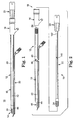
- FIG. 1 One preferred embodiment of a surgical micro-burring instrument 10 is illustrated in FIG. 1 .
- the instrument 10 includes an outer tubular assembly 12 and an inner tubular assembly 14 (referenced generally in FIG. 1 ).
- the outer tubular assembly 12 includes an outer hub 16 and an outer tubular member 18, whereas the inner tubular assembly 14 includes an inner hub 20, and an inner tubular member 22 (illustrated in FIG. 2 ).
- the inner tubular member 22 is sized to be coaxially received within the outer tubular member 18 and forms a bur 24.
- the micro-burring instrument 10 is configured to optimally perform a sinus surgical procedure, for example a septoplasty or turbinoplasty procedure.
- the outer tubular member 18 extends distally from the outer hub 16.
- the outer hub 16 can assume a wide variety of forms known in the art.
- an irrigation tube 30 is exteriorly secured to the outer tubular member 18.
- a connector 32 is provided at one end of the irrigation tube 30, adapted to fluidly connect the irrigation tube 30 with an irrigation reservoir (not shown).
- An opposite end of the irrigation tube 30 is fluidly connected to a portion of the outer tubular member 18 as described in greater detail below.
- the outer tubular assembly 12 can be adapted to internally deliver irrigation fluid via the outer tubular member 18. Even further, the irrigation feature can be eliminated entirely.
- the outer tubular member 18 is an elongated tubular body defining a proximal section 40, an intermediate section 42, a distal section 44, and a central lumen 46.
- the central lumen 46 extends from the proximal section 40 to the distal section 44.
- the distal section 44 forms a pocket or window 48 (referenced generally in FIG. 2 ) in fluid communication of the central lumen 46.
- the proximal section 40 is open at a proximal end 50 thereof to facilitate positioning of the inner tubular member 22 within the central lumen 46.
- the proximal section 40 is adapted to receive the outer hub 16, and thus has an appropriate outer diameter.
- the remainder of the outer tubular member 18, however, preferably provides a relatively uniform outer diameter selected to perform the desired sinus procedure and a relatively uniform inner diameter selected to rotatably receive the inner tubular member 22.
- the intermediate section 42, as well as the distal section 44 immediately proximal the pocket 48 has an inner diameter of approximately 3.5 mm that otherwise facilitates assembly and use of the inner tubular member 22/bur 24 as part of a septoplasty procedure. Alternatively, other dimensions can be employed.
- the distal section 44 of the outer tubular member 18 forms the pocket 48 that is otherwise in fluid communication with the central lumen 46.
- the distal section 44 includes a proximal portion 60, the pocket 48, and an elevator tip 62.
- the proximal portion 60 is adapted to be contiguous with the intermediate section 42 ( FIG. 2 ), providing a closed tubular section that continues the central lumen 46.
- the pocket 48 is formed distal the proximal portion 60, and the elevator tip 62 is formed distal the pocket 48.
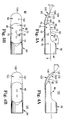
- the pocket 48 is defmed by a side wall 70 (referenced generally in FIG. 3A ) that forms a bottom surface 72, an end surface 74, and opposing side surfaces 76, and defines an upper opening 78 opposite the bottom surface 72.
- one or more ports 80 are formed through the bottom surface 72 that otherwise fluidly connects the pocket 48 with the irrigation tube 30 ( FIG. 1 ).
- the side surfaces 76 (one of which is shown in FIG. 3A ) terminate in an edge 82 that otherwise defines a perimeter of the upper opening 78.
- the edge 82 includes a proximal zone 84, an intermediate zone 86, and a distal zone 88.
- the proximal zone 84 extends downwardly (relative to the orientation of FIG. 3A ) in a primarily angular fashion from the proximal portion 60. In one embodiment, this angular extension forms an included angle ⁇ in the range of 100° - 140°, most preferably 120°, relative to a central axis A of the central lumen 46.
- the intermediate zone 86 extends in a primarily linear fashion (i.e., parallel with the central axis A) from the proximal zone 84. In one embodiment, relative to the longitudinal cross-sectional view of FIG. 3A , the intermediate zone 86 is aligned with the central axis A.
- the included angle ⁇ described above is thus also defined between the proximal and intermediate zones 84, 86 in longitudinal cross-section.
- the distal zone 88 extends downwardly (relative to the orientation of FIG. 3A ) from the intermediate zone 86.
- the distal zone 88 of the edge 82 defines a curve in longitudinal cross-section, with this curve being continued by the elevator tip 62.
- the preferred pocket 48 provides a relatively large upper opening 78 so as to expose a relatively large portion of the bur 24 ( FIG. 2 ) upon final assembly.
- other dimensions and/or configurations of the pocket 48 can also be employed.
- the elevator tip 62 extends distally from the pocket 48, and in particular a distal-most end 90 thereof.
- the elevator tip 62 includes an upper surface 100 and a lower surface 102 that combine to define a distal end point 104.
- the top surface 100 is generally defined by a proximal region 106 and a distal region 108.
- the proximal region 106 extends from the distal zone 88 of the pocket edge 82, preferably curving slightly upwardly (relative to the orientation of FIG. 3A ) approximately commensurate with the curvature defined by the distal zone 88.
- the distal region 108 extends upwardly (relative to an orientation of FIG.
- the elevator tip 62 has a distal extension (i.e., longitudinal distance between the distal most end point 90 of the pocket 48 and the distal end point 104 of the elevator tip 62 of at least 0.05 inch (1.27 mm); more preferably at least 0.1 inch (2.54 mm); even more preferably at least 0.139 inch (3.53 mm) such that the distal end point 104 of the elevator tip 64 is discernably spaced from the pocket 48.
- a distal extension i.e., longitudinal distance between the distal most end point 90 of the pocket 48 and the distal end point 104 of the elevator tip 62 of at least 0.05 inch (1.27 mm); more preferably at least 0.1 inch (2.54 mm); even more preferably at least 0.139 inch (3.53 mm) such that the distal end point 104 of the elevator tip 64 is discernably spaced from the pocket 48.
- FIGS. 4A and 4B illustrate an alternative embodiment distal section 120 (otherwise provided as part of a tubular member akin to the outer tubular member 18 shown in FIG. 2 ).
- the distal section 120 is similar to the distal section 44 ( FIGS. 3A and 3B previously described), and includes the proximal portion 60, the pocket 48, and an elevator tip 122.
- the proximal portion 60 and the pocket 48 are, in one embodiment, identical to the description provided above.
- the elevator tip 122 again includes an upper surface 124 and a lower surface 126 that connect at a distal end point 128.
- the upper surface 124 includes a proximal region 130 and a distal region 132.
- the proximal region 130 defines an upward curvature commensurate with the curvature of the distal zone 88 of the pocket edge 82.
- the distal region 132 has a smaller radius of a curvature (in longitudinal cross-section).
- the distal region 132 extends in a generally upward fashion (relative to the orientation of FIG. 4A ) from the proximal region 130, and is preferably generally linear in longitudinal cross-section.
- extension of the distal region 132 defines an included angle ⁇ of approximately 40° relative to the central axis A of the lumen 46, with the distal end point 128 being positioned above (relative to the orientation of FIG. 4A ) the central axis A and the intermediate zone 86 of the pocket edge 82.
- the distal end point 128 is positioned at least 0.1 inch (2.54 mm) from the distal most end point 90 of the pocket 48.
- the distal section 44 ( FIG. 3A ) or 120 ( FIG. 4A ) is formed separate from a remainder of the outer tubular member 18 ( FIG. 2 ) and subsequently is assembled thereto.
- the distal section 44, 120 can be formed from a material more amenable to precise manufacturing tolerances.
- the distal section 44, 120 is formed from heat-treated, 17-4 stainless steel, whereas a remainder of the outer tubular member is a 304 stainless steel material.
- the so-formed distal section 44, 120 is secured to the intermediate section 42 of the outer tubular member 18, such as by a laser weld.
- the inner tubular member 22 extends from the inner hub 20.
- the inner hub 20 is configured for selective attachment to a handpiece (described in greater detail below) that can be operated to automatically rotate the inner tubular member 22 during use.
- the inner tubular member 22 forms the bur 24 at a distal end thereof.
- the bur 24 can assume a variety of forms and is adapted to cut or abrade bodily tissue upon rotation thereof.
- the bur 24 forms a plurality of cutting flutes 138. While a cylindrical bur configuration is shown, it will be appreciated that other configurations can be used including, but not limited to, spherical, hemispherical, ellipsoidal, and pear-shaped configurations.
- the inner tubular member 22 defines a central lumen 140 that extends from a proximal end 142 thereof. As best shown in FIG. 5 , a distal end 144 of the bur 24 forms a hole 146 that is otherwise open to the central lumen 140. Alternatively, an exteriorly extending passage can be formed proximal the bur 24 that is otherwise fluidly connected to the central lumen 140. Regardless, the central lumen 140 serves as an aspiration conduit for the micro-burring instrument 10 ( FIG. 1 ) as described below.
- the micro-burring instrument 10 is assembled by coaxially positioning the inner tubular member 22 within the outer tubular member 18 via the central lumen 46.
- the inner hub 20 abuts against the outer hub 16.
- a position of the inner hub 20 relative to the bur 24 and a position of the outer hub 16 relative to the pocket 48 dictates a desired position of the bur 24 within the pocket 48 as best shown in FIG. 6 .
- the inner tubular member 22 is coaxially disposed within the outer tubular member 18 such that the bur 24 is within the pocket 48 and exposed relative to the outer tubular member 18 via the upper opening 78 provided by the pocket 48.
- a gap 150 is defined between the distal end 144 of the bur 24 and the distal end surface 74, and in particular the distal-most end point 90, of the pocket 48.
- the gap 150 is preferably provided to not only ensure free rotation of the bur 24 within the pocket 48, but also to provide sufficient space for delivery of irrigation fluid (such as the irrigation tube 30) and/or tissue removal via the aspiration lumen 140 otherwise provided by the inner tubular member 22.
- the gap 150 has a longitudinal dimension in the range of 0.0145 - 0.0255 inch (0.368 - 0.648 mm), more preferably 0.020 inch (0.508 mm).
- the bur 24 can be more closely positioned to the distal end of the surface 74 of the pocket 48.
- FIG. 7 illustrates an alternative embodiment micro-burring instrument 160 highly useful for a septoplasty procedure that again includes an outer tubular assembly 162 and an inner tubular assembly 164.
- the outer and inner tubular assemblies 162, 164 are, in one embodiment, highly similar to the outer and inner tubular assemblies 12, 14 ( FIG. 1 ), respectively, previously described.
- the outer and inner tubular members 162, 164 define a slight bend (referenced generally at 166) proximal a distal end portion 168 of the instrument 160.
- the bend 166 defines an angle ⁇ in the range of 10° - 14°, more preferably approximately 12°, relative to a central axis B of a proximal portion 170 of the instrument 160. This bend 166 is particularly useful in properly positioning the distal end portion 68 during a septoplasty procedure.
- an inner tubular member (hidden in the view of FIG. 7 , but akin to the inner tubular member 22 of FIG. 2 )) is preferably flexible, formed of an appropriate material such as spiral wrap technology. Alternatively, other constructions can be employed.
- FIG. 8 depicts a distal portion of an alternative embodiment micro-burring instrument 200 in accordance with the present invention.
- the micro-burring instrument 200 includes an inner tubular member 202 having a bur 204 at a distal end thereof, an intermediate tubular member 206 and an outer tubular member 208.
- the outer tubular member 208 forms an elevator tip 210, and is axially moveable along the intermediate tubular member 206 and thus is retractable relative to the bur 204 with respect to the position show in FIG. 8 .
- the inner tubular member 202 is preferably identical to the inner tubular member 22 ( FIG. 2 ) previously described.
- the intermediate tubular member 206 is preferably similar to the outer tubular member 18 ( FIG. 2 ) previously described, except that the intermediate tubular member 206 does not form an elevator tip. Instead, the intermediate tubular member 206 defines a window 212, through which the bur 204 is exposed, terminating at a curved distal wall 213 that is otherwise not configured to facilitate lifting of tissue.
- an irrigation tube (not shown, but akin to the irrigation tube 30 of FIG. 2 ) is structurally connected to an exterior of the intermediate tubular member 206 and fluidly connected to the window 212.
- the outer tubular member 208 forms a pocket 214 proximal the elevator tip 210.
- the elevator tip 210 can assume any of the forms previously described, as can the pocket 214.
- the pocket 214 is open relative to a central lumen 216 otherwise defined by, and extending to a proximal section (not shown) of, the outer tubular member 208.
- the central lumen 216 is sized such that the outer tubular member 208 is co-axially received over the intermediate tubular member 206 in a slidable fashion. That is to say, the outer tubular member 208 is axially slidable along an outer diameter of the intermediate tubular member 206 in a direction shown by the arrow "A" in FIG. 8 .
- the outer tubular member 208 serves as a sheath, and can be made from a variety of materials such as stainless steel, etc.
- the outer tubular member 208 forms a slot (not shown) that is received over the irrigation tube (not shown, but akin to the irrigation tube 30 of FIG. 2 ) otherwise affixed to the intermediate tubular member 206 to prevent the outer tubular member 208 from rotating relative to the intermediate tubular member 206.
- a hub component (not shown) is preferably connected to a proximal end of the outer tubular member 208 and is configured to selectively lock the outer tubular member 208 to the intermediate tubular member 206 at desired axial positions.
- an axial position of the elevator tip 210 relative to the bur 204 can be altered by sliding the outer tubular member 208 along the intermediate tubular member 206. With this configuration, then, an exposed length of the elevator tip 210 can be selectively increased to effectuate a desired tissue lifting or separating procedure. Subsequently, the elevator tip 210 can be axially retracted relative to the bur 204 and with some configurations, entirely removed from a region of the bur 204.
- FIGS. 9A and 9B A portion of yet another alternative embodiment micro-burring instrument 250 is shown in FIGS. 9A and 9B . Similar to the instrument 200 of FIG. 8 , the micro-burring instrument 250 includes an inner tubular member 252 having a bur 254 at a distal end thereof, an intermediate tubular member 256 and an outer tubular member 258. Once again, the outer tubular member 258 forms an elevator tip 260, and is axially moveable along the intermediate tubular member 256 and thus is axially moveable relative to the bur 254.
- the inner tubular member 252, including the bur 254, is preferably identical to previous embodiments.
- the intermediate tubular member 256 is also similar to the intermediate tubular member 206 ( FIG. 8 ) previously described, forming a window 262 and characterized by the absence of an elevator tip. As compared to the embodiment of FIG. 8 , the window 262 defines a larger opening in that a sidewall 264 thereof extends only slightly upwardly (relative to the orientation of FIG. 9A ).
- an irrigation tube 266 is affixed to an exterior of the intermediate tubular member 256 and is fluidly connected to the window 262.
- the outer tubular member 258 forms a pocket 268 proximal the elevator tip 260.
- the elevator tip 260 can assume any of the forms previously described.
- the pocket 268, and in particular a sidewall 270 that otherwise terminates at an edge 272 to define the pocket 268, is preferably similar in size and shape to the pocket 48 ( FIG. 3A ) previously described, and is fluidly connected to a central lumen 274 formed by the outer tubular member 258.
- the sidewall 270 forms a slot 276 opposite the edge 272 that is sized to receive the irrigation tube 266 upon final assembly.
- the central lumen 274 is sized to be co-axially received over, and axially slidable relative to, the intermediate tubular member 256.
- the elevator tip 260 is axially moveable relative to the bur 254 in a direction shown by arrow "B" in FIG. 9B , such that the outer tubular member 258 serves a sheath.
- interaction between the irrigation tube 266 and the slot 276 prevents the outer tubular member 258 from rotating relative to intermediate tubular member 256.
- the slot 276 and/or the irrigation tube 266 can be eliminated or replaced with varying constructions.
- the micro-burring instrument 10, 160, 200, 250 of the present invention is useful in performing various sinus operations, and finds particular usefulness as part of a septoplasty procedure.
- the assembled instrument 10 is deployed to the sinus target site.
- the elevator tip 62 is directed between the mucosal lining of the septum and the instrument 10 is then maneuvered to lift or elevate the mucosal lining from the septum cartilage and/or bone via the elevator tip 62.
- the instrument 10 is configured to allow axial movement of the elevator tip 62 relative to the bur 24 (such as with the instrument 200 of FIG. 8 or the instrument 250 of FIGS.
- the elevator tip 62 is axially extended relative to the bur 24 prior to lifting of the mucosal lining. Once sufficient elevation is achieved, the bur 24 is positioned against the targeted septum cartilage and/or bone. The inner tubular member 22 is then rotated relative to the outer tubular member 18, such that the bur 24 burs (e.g., cuts or abrades) the contacted cartilage and/or bone. Where the elevator tip 62 is axially moveable relative to the bur 24, the elevator tip 62 can be retracted prior to, during, or after rotation of the bur 24. Regardless, the pocket 48 and the bur 24, and thus the target site, are periodically or continuously flushed with an irrigation fluid via, for example, the irrigation tube 30 that is otherwise fluidly connected to the pocket 48.
- an irrigation fluid via, for example, the irrigation tube 30 that is otherwise fluidly connected to the pocket 48.
- the pocket 48 and thus the target site, is periodically or continuously aspirated via the central lumen 140 ( FIG. 5 ) of the inner tubular member 22 to remove abraded tissue from the pocket 48 and the target site.
- the central lumen 140 FIG. 5
- the bur 24 is stopped, and the instrument 10 removed from the target site, allowing the nasal lining mucous membrane to return to its natural position. If necessary, splints or packs are placed in the nasal cavity to ensure approximately mid-line positioning of the septum.
- the micro-burring instrument 10, 160, 200, 250 of the present invention can be used to perform a variety of other sinus procedures.
- submucosal removal of turbinate bone or septal bone/cartilage can be achieved with the instrument of the present invention, whereby only a relatively small puncture wound is required to provide sufficient access to the target site, in contrast to current techniques in which a relatively invasive incision is required to cut or resect turbinate bone (in addition to removal of other, softer tissue).
- the micro-burring instrument of the present invention is useful for performing a wide variety of surgical procedures in which soft tissue is desirably lifted from harder tissue and then the harder tissue (or portions thereof) removed in a minimally invasive fashion.
- soft tissue is desirably lifted from harder tissue and then the harder tissue (or portions thereof) removed in a minimally invasive fashion.
- sub-fascial and sub-perichrondrial removal of bony spurs in the spine are readily achieved in accordance with the present invention.
- the micro-burring instrument 10, 160 is attached to a powered handpiece as shown in FIG. 10 .
- the handpiece 280 can assume a variety of forms known in the art, and is in one preferred embodiment a StraightShot® powered handpiece, marketed by Medtronic-Xomed.
- the surgical micro-burring instrument of the present invention provides a marked improvement over previous designs. With respect to sinus surgeries, for example septoplasty procedures, use of a micro-burring instrument provides a distinct advantage over currently-accepted techniques requiring multiple, manual tools.
- the elevator tip associated with the present invention readily facilitates lifting or elevation of soft tissue (such as the nasal lining mucous membrane) from harder tissue (such as septal cartilage and/or bone), and positions a rotatable bur at the target site endoscopically.
Landscapes
- Health & Medical Sciences (AREA)
- Surgery (AREA)
- Life Sciences & Earth Sciences (AREA)
- Heart & Thoracic Surgery (AREA)
- Molecular Biology (AREA)
- Nuclear Medicine, Radiotherapy & Molecular Imaging (AREA)
- Veterinary Medicine (AREA)
- Public Health (AREA)
- Engineering & Computer Science (AREA)
- Biomedical Technology (AREA)
- General Health & Medical Sciences (AREA)
- Medical Informatics (AREA)
- Animal Behavior & Ethology (AREA)
- Orthopedic Medicine & Surgery (AREA)
- Otolaryngology (AREA)
- Dentistry (AREA)
- Oral & Maxillofacial Surgery (AREA)
- Pulmonology (AREA)
- Surgical Instruments (AREA)
- Materials For Medical Uses (AREA)
- Prostheses (AREA)
Claims (26)
- Chirurgisches Mikro-Entgratungsinstrument (10), das aufweist:ein äußeres rohrförmiges Element (18) mit einem proximalen Abschnitt (40), einem mittleren Abschnitt (42), einem distalen Abschnitt (44), und einem Zentrallumen (46), das sich von dem proximalen Abschnitt (40) zu dem distalen Abschnitt erstreckt, wobei der distale Abschnitt bildet:eine Tasche (48), die in Fluidverbindung mit dem Zentrallumen (46) steht, wobei die Tasche (48) eine Bodenfläche (22) und eine gegenüberliegende obere Öffnung (18) aufweist;eine Elevator- bzw. Hebespitze (62), die sich distal der Tasche erstreckt; und gekennzeichnet ist durchein inneres rohrförmiges Element (22), das drehbar innerhalb des Zentrallumens (46) aufgenommen ist, wobei ein distales Ende des inneren rohrförmigen Elements einen Grat (24) bildet, der innerhalb der Tasche positioniert ist, so dass nach Endmontage zumindest ein Teil des Grates (24) relativ zu dem äußeren Röhrenelement mittels der oberen Öffnung (28) der Tasche freigelegt ist.
- Instrument nach Anspruch 1, wobei die Tasche (48) an einem äußersten distalen Ende (90) endet und wobei ferner die Elevatorspitze (62) sich distal mindestens 1,27mm relativ zu dem äußersten distalen Ende (90) der Tasche erstreckt.
- Instrument nach Anspruch 2, wobei die Elevatorspitze (62) eine obere Fläche (100) aufweist, die sich von dem äußersten distalen Ende der Tasche erstreckt, wobei die obere Fläche (100) einen proximalen Bereich (106) und einen distalen Bereich (108) umfasst, wobei zumindest ein Teil des distalen Bereichs (108) sich von dem proximalen Bereich (106) im Längsschnitt in einer abgewinkelten bzw. winkelartigen Art und Weise erstreckt.
- Instrument nach Anspruch 3, wobei die abgewinkelte Verlängerung des distalen Bereichs (108) einen Öffnungswinkel im Bereich von 10° - 50° relativ zu einer Zentralachse des äußeren rohrförmigen Elements (18) definiert.
- Instrument nach Anspruch 4, wobei der Öffnungswinkel etwa 20° beträgt.
- Instrument nach Anspruch 4, wobei der Öffnungswinkel etwa 40° beträgt.
- Instrument nach Anspruch 3, wobei zumindest ein Teil des proximalen Bereichs (106) der oberen Fläche (100) der Elevatorspitze (62) sich von dem äußersten distalen Ende der Tasche nach unten erstreckt.
- Instrument nach Anspruch 7, wobei der proximale Bereich (106) im Längsschnitt gebogen bzw. gekrümmt ausgebildet ist.
- Instrument nach Anspruch 1, wobei die Elevatorspitze (62) in einem distalen Endpunkt endet, und ferner wobei der distale Endpunkt seitlich oberhalb einem äußersten distalen Ende der Tasche ist, wenn das äußere rohrförmige Element (18) ausgerichtet wird, so dass die Bodenfläche (22) der Tasche unterhalb der oberen Öffnung (78) ist.
- Instrument nach Anspruch 1, wobei der distale Abschnitt (44) ferner einen proximalen Abschnitt (60) proximal der Tasche aufweist, wobei der proximale Abschnitt (60) eine Röhre bildet, und ferner wobei die Tasche (48) durch eine Seitenwand (70) mit einer oberen Kante (82), die eine proximale Zone (84) umfasst, die sich von dem proximalen Bereich (60) in einer abgewinkelten Art und Weise nach unten erstreckt, definiert ist.
- Instrument nach Anspruch 10, wobei eine abgewinkelte Verlängerung der proximalen Zone (84) einen Öffnungswinkel im Bereich von 100° - 140° relativ zu einer Zentralachse des proximalen Teils (60) definiert.
- Instrument nach Anspruch 11, wobei der Öffnungswinkel etwa 120° beträgt.
- Instrument nach Anspruch 10, wobei die obere Kante (82) ferner eine mittlere Zone (86) aufweist, die sich parallel zu der Zentralachse des proximalen Abschnitts (60) von der proximalen Zone (84) erstreckt.
- Instrument nach Anspruch 10, wobei die obere Kante (82) ferner eine mittlere Zone (86), die sich von der proximalen Zone (84) erstreckt und eine distale Zone (88), die sich von der mittleren Zone (86) erstreckt, aufweist, wobei sich die distale Zone (88) relativ zu der mittleren Zone (86) nach unten erstreckt.
- Instrument nach Anspruch 1, wobei die Bodenfläche (22) zumindest eine Öffnung (78) bildet, die in Fluidverbindung mit einer Spülquelle (78) steht.
- Instrument nach Anspruch 15, das ferner aufweist:eine Spülröhre (30), der sich außen entlang des äußeren rohrförmigen Elements erstreckt und in Fluidverbindung mit der zumindest einen Öffnung (78) steht.
- Instrument nach Anspruch 1, wobei die Tasche ferner in einem äußersten distalen Endpunkt (90) endet, und wobei ferner nach Endmontage ein distales Ende (144) des Grates longitudinal von dem äußersten distalen Endpunkt (90) beabstandet ist.
- Instrument nach Anspruch 1, wobei das Instrument aufweist:eine Aspirationspassage, die sich durch das äußere rohrförmige Element (18) zum Aspirieren bzw. Absaugen von geschnittenem Gewebe erstreckt.
- Instrument nach Anspruch 18, wobei das innere rohrförmigen Element (22) ein Lumen bildet, das die Aspirationspassage bildet, wobei der Grat eine Öffnung an einem distalen Ende davon definiert und wobei ferner die Öffnung in Fluidverbindung mit dem Lumen des inneren rohrförmigen Elements (22) steht.
- Instrument nach Anspruch 1, wobei der mittlere Abschnitt (42) des äußeren rohrförmigen Elements (18) eine longitudinale Krümmung definiert.
- Instrument nach Anspruch 20, wobei die longitudinale Krümmung etwa 12° relativ zu einer Zentralachse, die durch den proximalen Bereich definiert wird, ist.
- Instrument nach Anspruch 1, wobei das Instrument zur Verwendung in einem Septoplastie-Verfahren eingerichtet ist.
- Instrument nach Anspruch 1, wobei die Elevatorspitze (62) wahlweise axial zu dem Grat (24) bewegbar ist.
- Instrument nach Anspruch 23, das ferner aufweist:ein mittleres rohrförmiges Element (256), das koaxial zwischen dem inneren rohrförmgies Element (252) und dem äußeren rohrförmigen Element (258) angeordnet ist, wobei das mittlere rohrförmige Element (256) ein distales Fenster (262) bildet, durch welches zumindest ein Teil des Grates freigelegt bzw. ausgesetzt ist;wobei das äußere rohrförmige Element (18) verschiebbar über dem mittlere rohrförmige Element (256) aufgenommen ist.
- Instrument nach Anspruch 1, wobei der Grat (24) eine Form ausgewählt aus der Gruppe bestehend aus zylindrisch, kugelförmig, halbkugelförmig, ellipsenförmig, und birnenförmig aufweist.
- Instrument nach Anspruch 1, wobei die Tasche (48) durch eine Seitenwand mit einer oberen Kante (82), die einen Umfang der oberen Öffnung definiert, definiert ist, wobei die obere Kante (82) eine proximale Zone, die sich von dem proximalen Bereich nach untern erstreckt, eine mittlere Zone, die sich von der proximalen Zone parallel zu einer Zentralachse des Lumens erstreckt und eine distale Zone, die sich von der mittleren Zone nach unten erstreckt, aufweist.
Applications Claiming Priority (2)
| Application Number | Priority Date | Filing Date | Title |
|---|---|---|---|
| US10/657,915 US7785337B2 (en) | 2003-09-09 | 2003-09-09 | Surgical micro-burring instrument and method of performing sinus surgery |
| PCT/US2004/028338 WO2005025429A2 (en) | 2003-09-09 | 2004-09-01 | Surgical micro-burring instrument and method of performing sinus surgery |
Publications (2)
| Publication Number | Publication Date |
|---|---|
| EP1667583A2 EP1667583A2 (de) | 2006-06-14 |
| EP1667583B1 true EP1667583B1 (de) | 2010-08-25 |
Family
ID=34226669
Family Applications (1)
| Application Number | Title | Priority Date | Filing Date |
|---|---|---|---|
| EP04782761A Expired - Lifetime EP1667583B1 (de) | 2003-09-09 | 2004-09-01 | Chirurgisches mikrofräsinstrument |
Country Status (9)
| Country | Link |
|---|---|
| US (2) | US7785337B2 (de) |
| EP (1) | EP1667583B1 (de) |
| JP (1) | JP4435165B2 (de) |
| AT (1) | ATE478617T1 (de) |
| AU (2) | AU2004271977B2 (de) |
| CA (1) | CA2537547C (de) |
| DE (1) | DE602004028844D1 (de) |
| ES (1) | ES2348722T3 (de) |
| WO (1) | WO2005025429A2 (de) |
Families Citing this family (80)
| Publication number | Priority date | Publication date | Assignee | Title |
|---|---|---|---|---|
| US20080121343A1 (en) | 2003-12-31 | 2008-05-29 | Microfabrica Inc. | Electrochemical Fabrication Methods Incorporating Dielectric Materials and/or Using Dielectric Substrates |
| US7585300B2 (en) | 2003-12-19 | 2009-09-08 | Spinascope, Inc. | Dissecting high speed burr for spinal surgery |
| US8221424B2 (en) | 2004-12-20 | 2012-07-17 | Spinascope, Inc. | Surgical instrument for orthopedic surgery |
| US8784421B2 (en) * | 2004-03-03 | 2014-07-22 | Boston Scientific Scimed, Inc. | Apparatus and methods for removing vertebral bone and disc tissue |
| US20050209610A1 (en) | 2004-03-03 | 2005-09-22 | Scimed Life Systems, Inc. | Radially adjustable tissue removal device |
| US20050197661A1 (en) * | 2004-03-03 | 2005-09-08 | Scimed Life Systems, Inc. | Tissue removal probe with sliding burr in cutting window |
| US20050261692A1 (en) * | 2004-05-21 | 2005-11-24 | Scimed Life Systems, Inc. | Articulating tissue removal probe and methods of using the same |
| US8328810B2 (en) * | 2004-06-17 | 2012-12-11 | Boston Scientific Scimed, Inc. | Slidable sheaths for tissue removal devices |
| US20110004215A1 (en) * | 2005-09-12 | 2011-01-06 | Bradley James P | Labrum retracting burr |
| RU2331374C1 (ru) * | 2007-02-05 | 2008-08-20 | Государственное образовательное учреждение дополнительного профессионального образования "Новокузнецкий государственный институт усовершенствования врачей Федерального агентства по здравоохранению и социальному развитию" | Способ лечения одонтогенного верхнечелюстного синусита |
| WO2009029083A1 (en) * | 2007-08-28 | 2009-03-05 | Yamada Jason M | Internal procedure for closing sinus membrane perforations |
| WO2009029081A1 (en) * | 2007-08-28 | 2009-03-05 | Yamada Jason M | Improved sinus membrane lifting and lateral separation instrument |
| US8906053B2 (en) | 2007-11-12 | 2014-12-09 | Medtronic Xomed, Inc. | Systems and methods for surgical removal of brain tumors |
| US20090287233A1 (en) * | 2008-05-15 | 2009-11-19 | Huculak John C | Small Gauge Mechanical Tissue Cutter/Aspirator Probe For Glaucoma Surgery |
| US10939934B2 (en) | 2008-06-23 | 2021-03-09 | Microfabrica Inc. | Miniature shredding tools for use in medical applications, methods for making, and procedures for using |
| US8795278B2 (en) | 2008-06-23 | 2014-08-05 | Microfabrica Inc. | Selective tissue removal tool for use in medical applications and methods for making and using |
| US8475458B2 (en) | 2008-06-23 | 2013-07-02 | Microfabrica Inc. | Miniature shredding tool for use in medical applications and methods for making |
| US9814484B2 (en) | 2012-11-29 | 2017-11-14 | Microfabrica Inc. | Micro debrider devices and methods of tissue removal |
| US9451977B2 (en) | 2008-06-23 | 2016-09-27 | Microfabrica Inc. | MEMS micro debrider devices and methods of tissue removal |
| US9125720B2 (en) | 2008-10-13 | 2015-09-08 | Alcon Research, Ltd. | Capsularhexis device with flexible heating element |
| US8137344B2 (en) | 2008-12-10 | 2012-03-20 | Alcon Research, Ltd. | Flexible, automated capsulorhexis device |
| US8157797B2 (en) | 2009-01-12 | 2012-04-17 | Alcon Research, Ltd. | Capsularhexis device with retractable bipolar electrodes |
| US8070765B2 (en) * | 2009-01-28 | 2011-12-06 | Medtronic Xomed, Inc. | Systems and methods for surgical removal of brain tumors |
| US8740811B2 (en) * | 2009-02-16 | 2014-06-03 | Dokter Yves Fortems Bvba | Biopsy device |
| EP2236100B1 (de) * | 2009-03-30 | 2017-06-28 | Arthrex, Inc. | Mikrobruchinstrument |
| US8814854B2 (en) * | 2009-06-03 | 2014-08-26 | Alcon Research, Ltd. | Capsulotomy repair device and method for capsulotomy repair |
| US20100312252A1 (en) * | 2009-06-03 | 2010-12-09 | Guangyao Jia | Capsularhexis device with flexible heating element having an angled transitional neck |
| WO2011022521A2 (en) | 2009-08-18 | 2011-02-24 | Microfabrica Inc. | Concentric cutting devices for use in minimally invasive medical procedures |
| US20140148729A1 (en) * | 2012-11-29 | 2014-05-29 | Gregory P. Schmitz | Micro-mechanical devices and methods for brain tumor removal |
| IN2012DN01917A (de) | 2009-09-08 | 2015-07-24 | Salient Surgical Tech Inc | |
| US20110202049A1 (en) * | 2010-02-18 | 2011-08-18 | Alcon Research, Ltd. | Small Gauge Ablation Probe For Glaucoma Surgery |
| US9241755B2 (en) | 2010-05-11 | 2016-01-26 | Alcon Research, Ltd. | Capsule polishing device and method for capsule polishing |
| US9149388B2 (en) | 2010-09-29 | 2015-10-06 | Alcon Research, Ltd. | Attenuated RF power for automated capsulorhexis |
| US9308013B2 (en) * | 2010-11-03 | 2016-04-12 | Gyrus Ent, L.L.C. | Surgical tool with sheath |
| US20120197320A1 (en) * | 2011-01-28 | 2012-08-02 | Laser Spine Surgical Center, LLC | Foraminoplasty Device |
| AU2012217764B2 (en) | 2011-02-15 | 2016-09-08 | Smith & Nephew, Inc. | Arthroscopic resection device |
| FI9329U1 (fi) * | 2011-03-21 | 2011-08-16 | Oulun Yliopisto | Luupora |
| EP2520236B1 (de) * | 2011-05-03 | 2015-07-15 | Eberle GmbH & Co. KG | Rotierendes chirugisches Instrument |
| US9226792B2 (en) | 2012-06-12 | 2016-01-05 | Medtronic Advanced Energy Llc | Debridement device and method |
| US9629646B2 (en) | 2012-07-11 | 2017-04-25 | Jens Kather | Curved burr surgical instrument |
| USD691718S1 (en) | 2012-08-23 | 2013-10-15 | Gyrus Acmi, Inc. | Microdebrider |
| US11234760B2 (en) | 2012-10-05 | 2022-02-01 | Medtronic Advanced Energy Llc | Electrosurgical device for cutting and removing tissue |
| US8920419B2 (en) | 2012-11-30 | 2014-12-30 | Gyrus Acmi, Inc. | Apparatus and method for tubeset with drive axle |
| US9848900B2 (en) | 2012-12-07 | 2017-12-26 | Ethicon Llc | Ultrasonic surgical blade |
| CN107252340B (zh) | 2013-02-26 | 2020-04-21 | 捷锐士阿希迈公司(以奥林巴斯美国外科技术名义) | 具有闭锁机构的可更换式清创器刀片模块 |
| USD707818S1 (en) | 2013-03-05 | 2014-06-24 | Alcon Research Ltd. | Capsulorhexis handpiece |
| US9358036B2 (en) | 2013-03-12 | 2016-06-07 | Gyrus Acmi, Inc. | Blade positioning device |
| US9290854B2 (en) | 2013-07-16 | 2016-03-22 | Microfabrica Inc. | Counterfeiting deterrent and security devices, systems and methods |
| KR101466747B1 (ko) * | 2013-09-27 | 2014-11-28 | 주의탁 | 견봉성형술용 천공 장치 |
| USD749730S1 (en) * | 2013-11-26 | 2016-02-16 | Ethicon Endo-Surgery, Llc | Blade for ultrasonic surgical instrument |
| US10314647B2 (en) | 2013-12-23 | 2019-06-11 | Medtronic Advanced Energy Llc | Electrosurgical cutting instrument |
| US9901364B2 (en) * | 2014-02-20 | 2018-02-27 | Gyrus Acmi, Inc. | Heat pipe cooled burr including surgical instruments embodying same |
| US10813686B2 (en) | 2014-02-26 | 2020-10-27 | Medtronic Advanced Energy Llc | Electrosurgical cutting instrument |
| USD737438S1 (en) | 2014-03-04 | 2015-08-25 | Novartis Ag | Capsulorhexis handpiece |
| US9636132B2 (en) | 2014-09-08 | 2017-05-02 | Medtronic Xomed, Inc. | Tumor debulker |
| US9737322B2 (en) | 2014-09-08 | 2017-08-22 | Medtronic Xomed, Inc. | Method for resection of tumors and tissues |
| US10231750B2 (en) * | 2014-09-29 | 2019-03-19 | Transmed7, Llc | Excisional device distal working end actuation mechanism and method |
| CN106456226B (zh) * | 2015-01-07 | 2019-08-23 | 奥林巴斯株式会社 | 超声波探头及超声波处理器具 |
| WO2016110854A1 (en) | 2015-01-08 | 2016-07-14 | Sinusafe Medical Ltd | Paranasal sinus medical device and uses thereof |
| US10376302B2 (en) | 2015-02-18 | 2019-08-13 | Medtronic Xomed, Inc. | Rotating electrical connector for RF energy enabled tissue debridement device |
| AU2016219980B2 (en) * | 2015-02-18 | 2020-09-03 | Medtronic Xomed, Inc. | RF energy enabled tissue debridement device |
| US10188456B2 (en) | 2015-02-18 | 2019-01-29 | Medtronic Xomed, Inc. | Electrode assembly for RF energy enabled tissue debridement device |
| US10022144B2 (en) | 2015-04-17 | 2018-07-17 | Medtronic Xomed, Inc. | Surgical cutting instrument |
| DE102015208646A1 (de) * | 2015-05-08 | 2016-11-10 | Frank Zastrow | Chirurgisches Handgerät sowie eine Schutzeinrichtung |
| DE102015209769A1 (de) * | 2015-05-28 | 2016-12-01 | Frank Zastrow | Chirurgisches Handgerät sowie ein Werkzeug und eine Schutzeinrichtung |
| EP3115004B1 (de) * | 2015-07-09 | 2022-11-02 | Carevature Medical Ltd. | Chirurgisches trennschleifinstrument |
| US10716612B2 (en) | 2015-12-18 | 2020-07-21 | Medtronic Advanced Energy Llc | Electrosurgical device with multiple monopolar electrode assembly |
| CN108430353B (zh) * | 2016-01-07 | 2021-06-11 | 迈克尔·D·史密斯 | 具有可缩回部的手持式手术装置 |
| US10349823B2 (en) | 2016-03-11 | 2019-07-16 | Colorado Voice Clinic, P.C. | Retractor and tip extender therefor |
| WO2018008020A1 (en) | 2016-07-03 | 2018-01-11 | Sinusafe Medical Ltd. | Medical device for treatment of a sinus and/or an ear and methods of use thereof |
| WO2018098187A1 (en) | 2016-11-23 | 2018-05-31 | Corit Llc | Apparatus and methods for tissue reduction |
| USD866759S1 (en) * | 2017-03-13 | 2019-11-12 | Colorado Voice Clinic, P.C. | Retractor |
| CN116327310A (zh) | 2017-07-25 | 2023-06-27 | 史赛克欧洲运营有限责任公司 | 用于与外科手术系统一起使用的冲洗套管 |
| US12023082B2 (en) | 2017-10-06 | 2024-07-02 | Medtronic Advanced Energy Llc | Hemostatic thermal sealer |
| US11185345B2 (en) * | 2018-01-31 | 2021-11-30 | Gyrus Acmi, Inc. | Debrider with external irrigation supply channel |
| CN108837188B (zh) * | 2018-04-20 | 2020-11-13 | 张福辛 | 一种腘窝囊肿治疗装置 |
| US11931056B2 (en) * | 2019-10-03 | 2024-03-19 | Gyrus Acmi, Inc. | Retractable elevator instrument shaver blade with flush/lavage features |
| EP4061255A1 (de) * | 2019-11-20 | 2022-09-28 | Smith&Nephew, Inc. | Mechanische resektionsklinge |
| US12336731B2 (en) * | 2021-10-22 | 2025-06-24 | Gyrus Acmi, Inc. | High speed burr with flex shaft cooling and improved suction |
| WO2025059653A1 (en) * | 2023-09-14 | 2025-03-20 | Arthrex, Inc. | Handheld resection medical device with integrated particulation system |
Family Cites Families (22)
| Publication number | Priority date | Publication date | Assignee | Title |
|---|---|---|---|---|
| US3844272A (en) | 1969-02-14 | 1974-10-29 | A Banko | Surgical instruments |
| US4530356A (en) * | 1983-02-08 | 1985-07-23 | Helfgott Maxwell A | Ophthalmic surgical instrument with beveled tip |
| US4850354A (en) * | 1987-08-13 | 1989-07-25 | Baxter Travenol Laboratories, Inc. | Surgical cutting instrument |
| AU650479B2 (en) * | 1990-10-19 | 1994-06-23 | Smith & Nephew, Inc. | Surgical device |
| US5364395A (en) * | 1993-05-14 | 1994-11-15 | West Jr Hugh S | Arthroscopic surgical instrument with cauterizing capability |
| US5685838A (en) | 1995-04-17 | 1997-11-11 | Xomed-Treace, Inc. | Sinus debrider apparatus |
| US5766199A (en) * | 1996-04-10 | 1998-06-16 | Linvatec Corporation | Endoscopic shaver blade with resilient cutting edges |
| US6503163B1 (en) * | 1996-05-15 | 2003-01-07 | Sensar, Inc. | Precision cable drive |
| EP1256322B1 (de) * | 1996-09-24 | 2005-12-07 | Xomed Surgical Products, Inc. | Zusammenbau von chirurgischen Klingen |
| US5741287A (en) * | 1996-11-01 | 1998-04-21 | Femrx, Inc. | Surgical tubular cutter having a tapering cutting chamber |
| US5913867A (en) * | 1996-12-23 | 1999-06-22 | Smith & Nephew, Inc. | Surgical instrument |
| WO1998049953A1 (en) * | 1997-05-09 | 1998-11-12 | Xomed Surgical Products, Inc. | Angled rotary tissue cutting instrument |
| US5964777A (en) * | 1997-12-11 | 1999-10-12 | Smith & Nephew, Inc. | Surgical cutting instrument |
| US6068641A (en) * | 1998-08-25 | 2000-05-30 | Linvatec Corporation | Irrigated burr |
| US6214009B1 (en) | 1998-09-09 | 2001-04-10 | Xomed Surgical Products, Inc. | Rhinoplasty bur |
| US6312443B1 (en) * | 1998-12-23 | 2001-11-06 | Nuvasive, Inc. | Expandable cannula |
| US6312438B1 (en) * | 2000-02-01 | 2001-11-06 | Medtronic Xomed, Inc. | Rotary bur instruments having bur tips with aspiration passages |
| DE20009786U1 (de) * | 2000-05-31 | 2000-10-19 | Taufig, Ahmmed Ziah, Dr., 51109 Köln | Fettabsaugvorrichtung |
| US6503263B2 (en) | 2000-09-24 | 2003-01-07 | Medtronic, Inc. | Surgical micro-shaving instrument with elevator tip |
| US6916328B2 (en) * | 2001-11-15 | 2005-07-12 | Expanding Concepts, L.L.C | Percutaneous cellulite removal system |
| AU2004259012C1 (en) * | 2003-07-23 | 2012-08-02 | Exelixis, Inc. | Anaplastic lymphoma kinase modulators and methods of use |
| US7908091B2 (en) * | 2006-03-17 | 2011-03-15 | Prometheus Laboratories Inc. | Methods of predicting and monitoring tyrosine kinase inhibitor therapy |
-
2003
- 2003-09-09 US US10/657,915 patent/US7785337B2/en active Active
-
2004
- 2004-09-01 JP JP2006526155A patent/JP4435165B2/ja not_active Expired - Fee Related
- 2004-09-01 CA CA2537547A patent/CA2537547C/en not_active Expired - Fee Related
- 2004-09-01 DE DE602004028844T patent/DE602004028844D1/de not_active Expired - Lifetime
- 2004-09-01 ES ES04782761T patent/ES2348722T3/es not_active Expired - Lifetime
- 2004-09-01 AU AU2004271977A patent/AU2004271977B2/en not_active Ceased
- 2004-09-01 WO PCT/US2004/028338 patent/WO2005025429A2/en not_active Ceased
- 2004-09-01 EP EP04782761A patent/EP1667583B1/de not_active Expired - Lifetime
- 2004-09-01 AT AT04782761T patent/ATE478617T1/de not_active IP Right Cessation
-
2010
- 2010-08-05 AU AU2010207765A patent/AU2010207765B2/en not_active Ceased
- 2010-08-09 US US12/852,834 patent/US8313489B2/en not_active Expired - Lifetime
Also Published As
| Publication number | Publication date |
|---|---|
| WO2005025429A3 (en) | 2007-03-08 |
| CA2537547A1 (en) | 2005-03-24 |
| CA2537547C (en) | 2012-11-06 |
| US8313489B2 (en) | 2012-11-20 |
| DE602004028844D1 (de) | 2010-10-07 |
| AU2010207765A1 (en) | 2010-09-02 |
| US20100298763A1 (en) | 2010-11-25 |
| ES2348722T3 (es) | 2010-12-13 |
| AU2004271977B2 (en) | 2010-06-24 |
| AU2004271977A1 (en) | 2005-03-24 |
| US20050054972A1 (en) | 2005-03-10 |
| US7785337B2 (en) | 2010-08-31 |
| JP2007521101A (ja) | 2007-08-02 |
| AU2010207765B2 (en) | 2011-09-15 |
| ATE478617T1 (de) | 2010-09-15 |
| JP4435165B2 (ja) | 2010-03-17 |
| WO2005025429A2 (en) | 2005-03-24 |
| EP1667583A2 (de) | 2006-06-14 |
Similar Documents
| Publication | Publication Date | Title |
|---|---|---|
| US7785337B2 (en) | Surgical micro-burring instrument and method of performing sinus surgery | |
| EP1322240B1 (de) | Endoskopische schaberklinge | |
| AU778501B2 (en) | Angled rotary tissue cutting instrument with flexible inner member | |
| US11523835B2 (en) | Arthroscopic drill blade and arthroscopic drill access system made therefrom | |
| AU2011232446B2 (en) | Arthroscopic resection devices | |
| EP2412320B1 (de) | Labrum-Einfahrgrat | |
| EP2667794B1 (de) | Chirurgisches schneidinstrument mit distaler saugkapazität | |
| JP5648122B2 (ja) | 切断性が改善され、軟性組織及び薄い骨の詰まりが軽減される回転切断処置具 | |
| EP2667803B1 (de) | Chirurgisches schneidinstrument mit distaler saugkapazität | |
| JP2005501648A (ja) | 可撓性の内側管状部材及び可撓性の内側管状部材を有する回転組織切削器具 | |
| US6214009B1 (en) | Rhinoplasty bur | |
| US7455679B2 (en) | Surgical elongate blade assembly with interchangeable inner member, kit and method relating thereto | |
| EP4541297A1 (de) | Chirurgische fräse mit gesteuerter bündelung |
Legal Events
| Date | Code | Title | Description |
|---|---|---|---|
| PUAI | Public reference made under article 153(3) epc to a published international application that has entered the european phase |
Free format text: ORIGINAL CODE: 0009012 |
|
| 17P | Request for examination filed |
Effective date: 20060410 |
|
| AK | Designated contracting states |
Kind code of ref document: A2 Designated state(s): AT BE BG CH CY CZ DE DK EE ES FI FR GB GR HU IE IT LI LU MC NL PL PT RO SE SI SK TR |
|
| AX | Request for extension of the european patent |
Extension state: AL HR LT LV MK |
|
| RAP1 | Party data changed (applicant data changed or rights of an application transferred) |
Owner name: MEDTRONIC XOMED, INC. |
|
| DAX | Request for extension of the european patent (deleted) | ||
| PUAK | Availability of information related to the publication of the international search report |
Free format text: ORIGINAL CODE: 0009015 |
|
| RIC1 | Information provided on ipc code assigned before grant |
Ipc: A61B 17/24 20060101ALI20070411BHEP Ipc: A61B 17/32 20060101AFI20070411BHEP |
|
| 17Q | First examination report despatched |
Effective date: 20090226 |
|
| RTI1 | Title (correction) |
Free format text: SURGICAL MICRO-BURRING INSTRUMENT |
|
| GRAP | Despatch of communication of intention to grant a patent |
Free format text: ORIGINAL CODE: EPIDOSNIGR1 |
|
| GRAS | Grant fee paid |
Free format text: ORIGINAL CODE: EPIDOSNIGR3 |
|
| GRAA | (expected) grant |
Free format text: ORIGINAL CODE: 0009210 |
|
| AK | Designated contracting states |
Kind code of ref document: B1 Designated state(s): AT BE BG CH CY CZ DE DK EE ES FI FR GB GR HU IE IT LI LU MC NL PL PT RO SE SI SK TR |
|
| REG | Reference to a national code |
Ref country code: GB Ref legal event code: FG4D |
|
| REG | Reference to a national code |
Ref country code: CH Ref legal event code: EP |
|
| REG | Reference to a national code |
Ref country code: IE Ref legal event code: FG4D |
|
| REF | Corresponds to: |
Ref document number: 602004028844 Country of ref document: DE Date of ref document: 20101007 Kind code of ref document: P |
|
| REG | Reference to a national code |
Ref country code: ES Ref legal event code: FG2A Effective date: 20101129 |
|
| REG | Reference to a national code |
Ref country code: NL Ref legal event code: VDEP Effective date: 20100825 |
|
| PG25 | Lapsed in a contracting state [announced via postgrant information from national office to epo] |
Ref country code: AT Free format text: LAPSE BECAUSE OF FAILURE TO SUBMIT A TRANSLATION OF THE DESCRIPTION OR TO PAY THE FEE WITHIN THE PRESCRIBED TIME-LIMIT Effective date: 20100825 Ref country code: FI Free format text: LAPSE BECAUSE OF FAILURE TO SUBMIT A TRANSLATION OF THE DESCRIPTION OR TO PAY THE FEE WITHIN THE PRESCRIBED TIME-LIMIT Effective date: 20100825 |
|
| PG25 | Lapsed in a contracting state [announced via postgrant information from national office to epo] |
Ref country code: CY Free format text: LAPSE BECAUSE OF FAILURE TO SUBMIT A TRANSLATION OF THE DESCRIPTION OR TO PAY THE FEE WITHIN THE PRESCRIBED TIME-LIMIT Effective date: 20100825 Ref country code: SI Free format text: LAPSE BECAUSE OF FAILURE TO SUBMIT A TRANSLATION OF THE DESCRIPTION OR TO PAY THE FEE WITHIN THE PRESCRIBED TIME-LIMIT Effective date: 20100825 Ref country code: PL Free format text: LAPSE BECAUSE OF FAILURE TO SUBMIT A TRANSLATION OF THE DESCRIPTION OR TO PAY THE FEE WITHIN THE PRESCRIBED TIME-LIMIT Effective date: 20100825 Ref country code: BG Free format text: LAPSE BECAUSE OF FAILURE TO SUBMIT A TRANSLATION OF THE DESCRIPTION OR TO PAY THE FEE WITHIN THE PRESCRIBED TIME-LIMIT Effective date: 20101125 |
|
| PG25 | Lapsed in a contracting state [announced via postgrant information from national office to epo] |
Ref country code: BE Free format text: LAPSE BECAUSE OF FAILURE TO SUBMIT A TRANSLATION OF THE DESCRIPTION OR TO PAY THE FEE WITHIN THE PRESCRIBED TIME-LIMIT Effective date: 20100825 Ref country code: NL Free format text: LAPSE BECAUSE OF FAILURE TO SUBMIT A TRANSLATION OF THE DESCRIPTION OR TO PAY THE FEE WITHIN THE PRESCRIBED TIME-LIMIT Effective date: 20100825 Ref country code: SE Free format text: LAPSE BECAUSE OF FAILURE TO SUBMIT A TRANSLATION OF THE DESCRIPTION OR TO PAY THE FEE WITHIN THE PRESCRIBED TIME-LIMIT Effective date: 20100825 Ref country code: GR Free format text: LAPSE BECAUSE OF FAILURE TO SUBMIT A TRANSLATION OF THE DESCRIPTION OR TO PAY THE FEE WITHIN THE PRESCRIBED TIME-LIMIT Effective date: 20101126 |
|
| PG25 | Lapsed in a contracting state [announced via postgrant information from national office to epo] |
Ref country code: DK Free format text: LAPSE BECAUSE OF FAILURE TO SUBMIT A TRANSLATION OF THE DESCRIPTION OR TO PAY THE FEE WITHIN THE PRESCRIBED TIME-LIMIT Effective date: 20100825 Ref country code: MC Free format text: LAPSE BECAUSE OF NON-PAYMENT OF DUE FEES Effective date: 20100930 |
|
| REG | Reference to a national code |
Ref country code: CH Ref legal event code: PL |
|
| PG25 | Lapsed in a contracting state [announced via postgrant information from national office to epo] |
Ref country code: SK Free format text: LAPSE BECAUSE OF FAILURE TO SUBMIT A TRANSLATION OF THE DESCRIPTION OR TO PAY THE FEE WITHIN THE PRESCRIBED TIME-LIMIT Effective date: 20100825 Ref country code: RO Free format text: LAPSE BECAUSE OF FAILURE TO SUBMIT A TRANSLATION OF THE DESCRIPTION OR TO PAY THE FEE WITHIN THE PRESCRIBED TIME-LIMIT Effective date: 20100825 Ref country code: EE Free format text: LAPSE BECAUSE OF FAILURE TO SUBMIT A TRANSLATION OF THE DESCRIPTION OR TO PAY THE FEE WITHIN THE PRESCRIBED TIME-LIMIT Effective date: 20100825 Ref country code: CZ Free format text: LAPSE BECAUSE OF FAILURE TO SUBMIT A TRANSLATION OF THE DESCRIPTION OR TO PAY THE FEE WITHIN THE PRESCRIBED TIME-LIMIT Effective date: 20100825 |
|
| PLBE | No opposition filed within time limit |
Free format text: ORIGINAL CODE: 0009261 |
|
| STAA | Information on the status of an ep patent application or granted ep patent |
Free format text: STATUS: NO OPPOSITION FILED WITHIN TIME LIMIT |
|
| PG25 | Lapsed in a contracting state [announced via postgrant information from national office to epo] |
Ref country code: LI Free format text: LAPSE BECAUSE OF NON-PAYMENT OF DUE FEES Effective date: 20100930 Ref country code: IE Free format text: LAPSE BECAUSE OF NON-PAYMENT OF DUE FEES Effective date: 20100901 Ref country code: CH Free format text: LAPSE BECAUSE OF NON-PAYMENT OF DUE FEES Effective date: 20100930 |
|
| 26N | No opposition filed |
Effective date: 20110526 |
|
| REG | Reference to a national code |
Ref country code: DE Ref legal event code: R097 Ref document number: 602004028844 Country of ref document: DE Effective date: 20110526 |
|
| PG25 | Lapsed in a contracting state [announced via postgrant information from national office to epo] |
Ref country code: LU Free format text: LAPSE BECAUSE OF NON-PAYMENT OF DUE FEES Effective date: 20100901 Ref country code: HU Free format text: LAPSE BECAUSE OF FAILURE TO SUBMIT A TRANSLATION OF THE DESCRIPTION OR TO PAY THE FEE WITHIN THE PRESCRIBED TIME-LIMIT Effective date: 20110226 |
|
| PG25 | Lapsed in a contracting state [announced via postgrant information from national office to epo] |
Ref country code: TR Free format text: LAPSE BECAUSE OF FAILURE TO SUBMIT A TRANSLATION OF THE DESCRIPTION OR TO PAY THE FEE WITHIN THE PRESCRIBED TIME-LIMIT Effective date: 20100825 |
|
| PG25 | Lapsed in a contracting state [announced via postgrant information from national office to epo] |
Ref country code: PT Free format text: LAPSE BECAUSE OF NON-PAYMENT OF DUE FEES Effective date: 20100825 |
|
| REG | Reference to a national code |
Ref country code: FR Ref legal event code: PLFP Year of fee payment: 13 |
|
| REG | Reference to a national code |
Ref country code: FR Ref legal event code: PLFP Year of fee payment: 14 |
|
| REG | Reference to a national code |
Ref country code: FR Ref legal event code: PLFP Year of fee payment: 15 |
|
| PGFP | Annual fee paid to national office [announced via postgrant information from national office to epo] |
Ref country code: IT Payment date: 20200824 Year of fee payment: 17 |
|
| PG25 | Lapsed in a contracting state [announced via postgrant information from national office to epo] |
Ref country code: IT Free format text: LAPSE BECAUSE OF NON-PAYMENT OF DUE FEES Effective date: 20210901 |
|
| PGFP | Annual fee paid to national office [announced via postgrant information from national office to epo] |
Ref country code: ES Payment date: 20221003 Year of fee payment: 19 |
|
| PGFP | Annual fee paid to national office [announced via postgrant information from national office to epo] |
Ref country code: GB Payment date: 20230823 Year of fee payment: 20 |
|
| PGFP | Annual fee paid to national office [announced via postgrant information from national office to epo] |
Ref country code: FR Payment date: 20230822 Year of fee payment: 20 Ref country code: DE Payment date: 20230822 Year of fee payment: 20 |
|
| REG | Reference to a national code |
Ref country code: DE Ref legal event code: R071 Ref document number: 602004028844 Country of ref document: DE |
|
| REG | Reference to a national code |
Ref country code: GB Ref legal event code: PE20 Expiry date: 20240831 |
|
| PG25 | Lapsed in a contracting state [announced via postgrant information from national office to epo] |
Ref country code: GB Free format text: LAPSE BECAUSE OF EXPIRATION OF PROTECTION Effective date: 20240831 |
|
| REG | Reference to a national code |
Ref country code: ES Ref legal event code: FD2A Effective date: 20241025 |
|
| PG25 | Lapsed in a contracting state [announced via postgrant information from national office to epo] |
Ref country code: GB Free format text: LAPSE BECAUSE OF EXPIRATION OF PROTECTION Effective date: 20240831 |
|
| PG25 | Lapsed in a contracting state [announced via postgrant information from national office to epo] |
Ref country code: ES Free format text: LAPSE BECAUSE OF NON-PAYMENT OF DUE FEES Effective date: 20230902 |
|
| PG25 | Lapsed in a contracting state [announced via postgrant information from national office to epo] |
Ref country code: ES Free format text: LAPSE BECAUSE OF NON-PAYMENT OF DUE FEES Effective date: 20230902 |