EP1667328A1 - Method and apparatus for generating a low-density parity check (LDPC) code - Google Patents
Method and apparatus for generating a low-density parity check (LDPC) code Download PDFInfo
- Publication number
- EP1667328A1 EP1667328A1 EP05025980A EP05025980A EP1667328A1 EP 1667328 A1 EP1667328 A1 EP 1667328A1 EP 05025980 A EP05025980 A EP 05025980A EP 05025980 A EP05025980 A EP 05025980A EP 1667328 A1 EP1667328 A1 EP 1667328A1
- Authority
- EP
- European Patent Office
- Prior art keywords
- matrix
- parity
- parity check
- matrices
- delta
- Prior art date
- Legal status (The legal status is an assumption and is not a legal conclusion. Google has not performed a legal analysis and makes no representation as to the accuracy of the status listed.)
- Granted
Links
Images


Classifications
-
- H—ELECTRICITY
- H03—ELECTRONIC CIRCUITRY
- H03M—CODING; DECODING; CODE CONVERSION IN GENERAL
- H03M13/00—Coding, decoding or code conversion, for error detection or error correction; Coding theory basic assumptions; Coding bounds; Error probability evaluation methods; Channel models; Simulation or testing of codes
- H03M13/03—Error detection or forward error correction by redundancy in data representation, i.e. code words containing more digits than the source words
- H03M13/05—Error detection or forward error correction by redundancy in data representation, i.e. code words containing more digits than the source words using block codes, i.e. a predetermined number of check bits joined to a predetermined number of information bits
- H03M13/11—Error detection or forward error correction by redundancy in data representation, i.e. code words containing more digits than the source words using block codes, i.e. a predetermined number of check bits joined to a predetermined number of information bits using multiple parity bits
-
- H—ELECTRICITY
- H03—ELECTRONIC CIRCUITRY
- H03M—CODING; DECODING; CODE CONVERSION IN GENERAL
- H03M13/00—Coding, decoding or code conversion, for error detection or error correction; Coding theory basic assumptions; Coding bounds; Error probability evaluation methods; Channel models; Simulation or testing of codes
- H03M13/63—Joint error correction and other techniques
- H03M13/635—Error control coding in combination with rate matching
- H03M13/6362—Error control coding in combination with rate matching by puncturing
-
- G—PHYSICS
- G06—COMPUTING; CALCULATING OR COUNTING
- G06F—ELECTRIC DIGITAL DATA PROCESSING
- G06F11/00—Error detection; Error correction; Monitoring
- G06F11/07—Responding to the occurrence of a fault, e.g. fault tolerance
- G06F11/08—Error detection or correction by redundancy in data representation, e.g. by using checking codes
- G06F11/10—Adding special bits or symbols to the coded information, e.g. parity check, casting out 9's or 11's
-
- H—ELECTRICITY
- H03—ELECTRONIC CIRCUITRY
- H03M—CODING; DECODING; CODE CONVERSION IN GENERAL
- H03M13/00—Coding, decoding or code conversion, for error detection or error correction; Coding theory basic assumptions; Coding bounds; Error probability evaluation methods; Channel models; Simulation or testing of codes
- H03M13/03—Error detection or forward error correction by redundancy in data representation, i.e. code words containing more digits than the source words
- H03M13/05—Error detection or forward error correction by redundancy in data representation, i.e. code words containing more digits than the source words using block codes, i.e. a predetermined number of check bits joined to a predetermined number of information bits
- H03M13/11—Error detection or forward error correction by redundancy in data representation, i.e. code words containing more digits than the source words using block codes, i.e. a predetermined number of check bits joined to a predetermined number of information bits using multiple parity bits
- H03M13/1102—Codes on graphs and decoding on graphs, e.g. low-density parity check [LDPC] codes
- H03M13/1148—Structural properties of the code parity-check or generator matrix
- H03M13/116—Quasi-cyclic LDPC [QC-LDPC] codes, i.e. the parity-check matrix being composed of permutation or circulant sub-matrices
-
- H—ELECTRICITY
- H03—ELECTRONIC CIRCUITRY
- H03M—CODING; DECODING; CODE CONVERSION IN GENERAL
- H03M13/00—Coding, decoding or code conversion, for error detection or error correction; Coding theory basic assumptions; Coding bounds; Error probability evaluation methods; Channel models; Simulation or testing of codes
- H03M13/03—Error detection or forward error correction by redundancy in data representation, i.e. code words containing more digits than the source words
- H03M13/05—Error detection or forward error correction by redundancy in data representation, i.e. code words containing more digits than the source words using block codes, i.e. a predetermined number of check bits joined to a predetermined number of information bits
- H03M13/11—Error detection or forward error correction by redundancy in data representation, i.e. code words containing more digits than the source words using block codes, i.e. a predetermined number of check bits joined to a predetermined number of information bits using multiple parity bits
- H03M13/1102—Codes on graphs and decoding on graphs, e.g. low-density parity check [LDPC] codes
- H03M13/1148—Structural properties of the code parity-check or generator matrix
- H03M13/118—Parity check matrix structured for simplifying encoding, e.g. by having a triangular or an approximate triangular structure
- H03M13/1185—Parity check matrix structured for simplifying encoding, e.g. by having a triangular or an approximate triangular structure wherein the parity-check matrix comprises a part with a double-diagonal
- H03M13/1188—Parity check matrix structured for simplifying encoding, e.g. by having a triangular or an approximate triangular structure wherein the parity-check matrix comprises a part with a double-diagonal wherein in the part with the double-diagonal at least one column has an odd column weight equal or greater than three
Definitions
- the present invention relates generally to data coding.
- the present invention relates to a method and apparatus for generating a low-density parity check (LDPC) code.
- LDPC low-density parity check
- communication systems encode transmission data prior to transmission to increase transmission stability, avoiding retransmissions and increasing transmission efficiency.
- they use convolutional coding, turbo coding, etc.
- LDPC codes have emerged as a promising coding method.
- the LDPC codes were first proposed by Gallager in the early 1960's and rediscovered by MacKay after the 1990's.
- MacKay's LDPC code is based on decoding using the sum-product algorithm. Using belief propagation, these LDPC codes have attracted attention as a code having excellent performance that approaches the Shannon capacity limit.
- the basic idea of the density evolution is to track the probability distributions of messages generated and updated during decoding, which change according to the number of iterations, on a factor graph describing a LDPC code. Under the assumption of the density evolution and infinite iterations on the factor graph, a channel parameter was detected which converges the probability of error to "0". That is, the degree distributions of variable nodes and check nodes, which maximize the channel parameter on the factor graph, were proposed. They theoretically demonstrated that this case is also applicable to LDPC codes of a finite length with cycles. With this density evolution technique, the channel capacity of irregular LDPC codes approaches to within 0.0045dB of the theoretical Shannon limit.
- LDPC codes are discussed as a prominent alternative to turbo codes for future-generation mobile communication systems. This is because the LDPC codes have parallel structure and low complexity in the design of a decoder, low error-floor performance, and good frame error rate. Accordingly, it is expected that excellent LDPC codes will be proposed with more developmental efforts over the coming years.
- Distinctive shortcomings with conventional LDPC codes are greater complexity in terms of coding relative to turbo coding, difficulty in deciding an optimum code structure that offers better performance than turbo codes, for a short frame size, and require a large memory for LDPC code representation. Therefore, a need exists for an efficient LDPC code having flexibility in frame length.
- An object of the present invention is to substantially solve at least the above problems and/or disadvantages and to provide at least the advantages below. Accordingly, an object of the present invention is to provide a method and apparatus for generating a low density parity check (LDPC) code which can be implemented with simple coding.
- LDPC low density parity check
- Another object of the present invention is to provide a method and apparatus for generating a block LDPC code which can be implemented with simple coding.
- a parity check matrix is formed which has (N-K) rows for check nodes and N columns for variable nodes to encode an information sequence of length K to a codeword of length N.
- the parity check matrix is divided into an information part matrix having K columns and a parity part matrix having (N-k) columns.
- the parity part matrix is divided into PxP subblocks. P is a divisor of (N-K).
- a first diagonal and a second diagonal are defined in the parity part matrix such that the second diagonal is a shift of the first diagonal by f subblocks. Shifted identity matrices with shift indexes are placed in subblocks that lie on the first and second diagonals.
- Zero matrices are filled in the remaining subblocks other than the subblocks of the first and second diagonals.
- An odd number of delta matrices are placed in one subblock column of the parity part matrix.
- Each delta matrix comprises one element of 1 and the other elements of 0.
- the parity check matrix is stored.
- Low density parity check (LDPC) codes are a class of linear block codes.
- the structure of a LDPC code is defined by a parity check matrix containing 0s at most entries and 1s elsewhere.
- an (N, K) LDPC code for K information bits is a linear block code with a block size of N, defined by a sparse (N-K)xN parity check matrix in which all elements other than 1s are 0s.
- the number of 1s in a row or a column is called the degree of the row or the column.
- a LDPC code is regular when each row and each column of the parity check matrix has a constant degree and irregular otherwise. It is generally known that the irregular LDPC code outperforms the regular one. Due to different degrees among rows and among columns, however, the irregular LDPC code promises excellent performance only if the row degrees and the column degrees are appropriately adjusted.
- a codeword of length N is represented as a vector C and for information bits of length K, an (N, K) code with 2 K codewords is used.
- FIG. 1 illustrates a parity check matrix that defines a conventional (10, 5) LDPC code.
- the parity check matrix H for the LDPC code is comprised of 5 rows and 10 columns.
- the columns have a uniform degree of 2 and the rows have a uniform degree of 4.
- the (10, 5) LDPC code is regular.
- FIG. 2 illustrates a factor graph describing the LDPC code illustrated in FIG. 1.
- the factor graph of the LDPC code contains 10 variable nodes 20, represented by V 1 to V 10 and 5 check nodes 22, represented by C 1 to C 5 .
- an edge (or branch) 24 connects an i th variable node, V i with a j th check node, C j .
- the parity check matrix of the LDPC code has a very small degree, message passing iterative decoding using the sum-product algorithm is available for a relatively long block code. As the block size of the block code is continually increased, it has performance close to the Shannon channel capacity limit, like turbo codes.
- LDPC decoding is the process of iteratively exchanging messages generated and updated at individual nodes between the variable nodes and the check nodes on the factor graph. In the operation, the nodes update the messages using the sum-product algorithm. This iterative LDPC decoding is depicted in FIGs. 3A and 3B.
- a check node 22a creates a check node message 24 for one of variable nodes 20b connected to the check node 22a by summing variable node values received from the other variable nodes 20b.
- a variable node 20a creates a variable node message 26 for one of check nodes 22b connected to the variable node 20a by multiplying check node values received from the other check nodes 22b.
- check node messages and variable node messages are transferred along the edges connecting between them.
- the parity check matrix has less 1s, the number of messages to be delivered decreases, thereby reducing the computation volume and memory space for decoding.
- Efficient LDPC coding is an active research area.
- a parity sequence Cp containing (N-K) parity bits is generated using an information sequence of length K, C 1 and an (N-K)xN parity check matrix.
- the information part of the parity check matrix is designed, taking into account the cycle and density evolution characteristics of the LDPC code, which is beyond the scope of the present invention. Therefore, it will not be described in detail herein.
- FIG. 4 illustrates an exemplary parity check matrix for efficient LDPC coding.
- a parity check matrix 100 is divided into an information part 102 and a parity part 104.
- Elements of 1 lie on a first diagonal which starts with the element in the first row and the first column and ends with the element in the last row and the last column of the parity part 104 being a square matrix.
- a second diagonal which starts with the element in the first row and the second column, also has elements of 1.
- the second diagonal is a cyclic shift of the first diagonal by 1.
- the parity check matrix 100 is designed to comprise an odd number of 1s in a first row 106, to thereby sequentially generate parity bits, eliminating columns having a degree of 1.
- the elements other than 1s explicitly shown in FIG. 4 are all 0s.
- h j I C I T is calculated for every row, and then a (z+1) th parity bit is calculated in the following manner, while accumulating the obtained values.
- a block-type LDPC code with the expanded parity part advantageously can be represented with a smaller memory capacity, has flexibility in frame length, and enables simple decoder implementation, relative to an irregular LDPC code.
- the block-type LDPC code is called interchangeably with a vector LDPC code, a block LDPC code, or a GDM LDPC code.
- the parity check matrix of the GDM LDPC code has matrices created by cyclically shifting the rows of the PxP identity matrix I by 's', as subblocks. 's' is a shift index.
- a (27, 15) GDM LDPC code is taken as an example.
- the parity check matrix 110 is divided into an information part 112 and a parity part 114.
- the parity part 114 is divided into subblocks each being a 3x3 matrix. Therefore, the parity part 114 has 4 subblock rows and 4 subblock columns.
- the information part 112 comprises only zero matrices or shifted identity matrices, and the positions of the non-zero subblocks and the shift index s of the shifted identity matrices are determined by taking into account the density evolution and cycle characteristics of the code.
- Shifted identity matrices are placed on a first diagonal starting with the first subblock row and the first subblock column and ending with the last subblock row and the last subblock column.
- One thing to note is that one 116 of the shifted identity matrices on the first diagonal in the parity part 114 has a 1 punctured.
- a second diagonal starting with the first subblock row and the second subblock column has also shifted identity matrices.
- the second diagonal is a cyclic shift of the first diagonal by 1.
- the empty subblocks in the parity part 114 are zero matrices.
- the shifted identity matrices are matrices shifted from the identity matrix I diagonally.
- the diagonals in the parity part 114 illustrated in FIG. 5 have ⁇ s subblocks.
- the shifted identity matrix is a cyclic permutation matrix created by cyclically shifting every column of the identity matrix I.
- a GDM LDPC code is created using the parity part of the parity check matrix illustrated in FIG. 6.
- FIG. 6 only 1s lie on diagonal lines 30a, 30b and 32 in the illustrated binary matrix.
- the dual-diagonal matrix is so configured that the second diagonals 30a and 30b is a shift of the first diagonal 32 by 'f'.
- Placing 0 as the first entry of the second diagonal 30a i.e. puncturing
- FIG. 7 illustrates a block parity part expanded from the parity part illustrated in FIG. 6.
- the illustrated parity part comprises shifted identity matrices ⁇ j on first and second diagonals 40, 42a and 42b and zero matrices elsewhere.
- Shifted identity matrices with shift indexes 0, 2, ..., 2(r-f-1), 2(r-f), 2(r-1) lie on the first diagonal 40.
- the second diagonals 42a and 42b which are a shift of the first diagonal 40 by f subblocks, have shifted identity matrices with shift indexes 1, 3, ..., 2(r-f-1)+1, ... 2(r-f)+1, ... 2(r-1)+1. Every shifted identity matrix is of size PxP and thus the second diagonal 42a is apart from the first diagonal 40 by Pxf columns.
- parity part if 1s in the first row of the first shifted identity matrix ⁇ jl on the first diagonal is changed to 0s instead of replacing the first shifted identity matrix ⁇ jl by a zero matrix, all parity bits can be encoded by circulating the entire non-zero elements.
- the shift index j i of each subblock is determined such that all parity bits can be sequentially encoded.
- a parity check matrix 120 comprises an information part 122 and a parity part 124.
- the parity part 124 is filled with zero matrices except in subblocks on two diagonals. A first diagonal starts with the subblock in the first subblock row and the first subblock column and ends with the subblock in the last subblock row and the last subblock column.
- the second diagonal is produced by shifting the first diagonal 2 subblocks and has shifted identity matrices thereon.
- the first coded parity bit is obtained from a 7 th element 126 in the first row according to Eq. (5).
- the following parity bits are encoded along the arrowed directions, ending with the last parity bit from a 12 th element 128 of the first column.
- FIG. 9 illustrates the structure of the parity part of a parity check matrix according to an embodiment of the present invention.
- the information part of the parity check matrix is not shown here because it is not related to the subject matter of the present invention.
- the parity part comprises shifted identity matrices ⁇ j on diagonals 50, 50a and 50b and zero matrices elsewhere.
- j is an integer between 0 and 2(r-1) where r is (n-k).
- Shifted identity matrices with even shift indexes 0, 2, ..., 2(r-f-1), 2(r-f), 2(r-1) lie on the first diagonal 50.
- the second diagonals 52a and 52b which are a shift of the first diagonal 40 by f subblocks, have shifted identity matrices with odd shift indexes 1, 3, ..., 2(r-f-1)+1, ... 2(r-f)+1, ... 2(r-1)+1.
- the shift indexes of the shifted identity matrices are determined in the manner that maximizes the performance of the LDPC code and simplifies decoder structure. How to determine the shift indexes are beyond the scope of the present invention and will not be described herein.
- delta matrices ⁇ i are inserted into a subblock column 54 including a column of degree 1.
- the delta matrices ⁇ i are of size PxP like the shifted identity matrices and every delta matrix has 1 at an i th bit of the first column.
- i is an integer between 0 and (P-1) and ⁇ -1 is a zero matrix.
- the subblock column 54 includes (n-k-2) delta matrices. (n-k-2) is an odd number and the positions of the delta matrices are randomly decided.
- parity bits can be encoded sequentially.
- FIG. 10 illustrates a LDPC code and the associated LDPC coding according to an embodiment of the present invention.
- Numerals written in small squares representing elements denote the sequence of encoding parity bits.
- Twodiagonals 154, 156a and 156b are defined in the parity part 144.
- a first subblock column 150 of the parity part 144 has two shifted identity matrices 154 and 156 and one delta matrix 152.
- FIG. 11 is a block diagram of a LDPC code generating apparatus according to an embodiment of the present invention.
- a computer system 200 comprises a processor 212 connected to a memory system 218 via a system bus 230.
- the processor 212 reads necessary parameters from the memory system 218, generates a LDPC code using the parameters, and stores the LDPC code in the memory system 218.
- the processor 212 may be connected to a main memory 210, an input device 214, and an output device 216 via the system bus 230.
- a user enters a command to the processor 212 via the system bus 230 by manipulating the input device 214.
- the processor 212 operates according to the command signal and displays the operation result to the user via the output device 216.
- the operation result may be stored in the memory system 218 upon user request.
- the LDPC generating operation is implemented by storing known corresponding computer programs codes in the memory system 218 or designing corresponding hardware logic.
- the parameters needed for generation of the LDPC code or programs codes needed to calculate the parameters are stored in the memory system 218.
- the LDPC code generated by the processor 212 is stored in the memory system 218 on a subblock-by-subblock basis.
- FIG. 12 is a flowchart illustrating a LDPC code generating operation according to an embodiment of the present invention.
- the LDPC code generating operation generates a parity check matrix that defines a LDPC code.
- a parity check matrix is formed which comprises (N-K) rows for check nodes and N columns for variable nodes in order to encode an information sequence of length K to a codeword of length N in step 300.
- the parity check matrix is divided into an information part matrix with K columns and a parity part matrix with (N-K) columns in step 302.
- the parity part matrix is further divided into PxP subblocks. P is a divisor of (N-K).
- first and second diagonals are determined.
- the first diagonal runs from the first subblock row and subblock column to the last subblock row and subblock column, and the second diagonal is a shift of the first diagonal by f subblocks.
- Shifted identity matrices with predetermined shift indexes j i are placed in the subblocks on the first and second diagonals in step 308.
- f and j i are determined such that the coding performance of the parity check matrix is maximized. Compared to a conventional GDM LDPC code, none of the elements on the first and second diagonals are punctured.
- step 310 zero matrices are filled elsewhere.
- An odd number of zero matrices in a subblock column comprising a column of degree 1 are replaced with delta matrices in the parity part matrix in step 312.
- the delta matrices are defined as matrices each containing 1 at only one entry and 0s elsewhere.
- the parity check matrix is stored in the memory system in step 314.
- FIG. 13 illustrates an exemplary realization of the parity part of an LDPC code according to the preferred embodiment of the present invention.
- subblocks on dual diagonals are all identity matrices I in a parity part H P .
- ⁇ s is a matrix shifted from the identity matrix by s.
- insertion of the delta matrix ⁇ 0 in the first subblock column eliminates the column of degree 1, thereby facilitating LDPC coding.
- s is prime with P denoting a subblock size.
- This LDPC code offers the benefits of a very simple parity structure and very regular coding of parity bits.
- the coding order is given as p 0 ⁇ p P ⁇ p 2 P ... ⁇ p ( n ⁇ k ⁇ 1 ) P ⁇ p I ⁇ p P + I ... ⁇ p N ⁇ K ⁇ 1
- a parity check matrix 160 has an information part 162 and a parity part 164.
- 3x3 identity matrices are placed on dual diagonals 170, 172a and 172b.
- the first subblock column comprises a 1-shifted identity matrix 168 and a delta matrix 166 with only one element of 1.
- the above-described systematic LDPC code has subblocks of shifted identity matrices and subblocks of delta matrices (i.e. delta blocks).
- the memory system preserves the parameters needed to represent the block LDPC code, that is, information about the degree of every check node, the degree of every variable node, the positions of non-zero matrices in every row, and the shift index s of every non-zero matrix. These parameters are expressed as positive integers.
- the memory system stores the delta blocks discriminately from the other subblocks.
- the memory system manages 1-bit subblock information indicating whether each subblock being a non-zero matrix comprises a delta matrix or a shifted identity matrix.
- s represents a shift index for a subblock with a shifted identity matrix, and s also represents the position of 1 for a subblock with a delta matrix.
- the parity check matrix is retrieved from the memory system to a LDPC encoder/decoder.
- the LDPC encoder computes a parity sequence Cp by Eq. (12) using an input information sequence C 1 and the parity check matrix and concatenates C 1 and C P into a codeword C.
- the codeword is transmitted to a receiver through a modulator and a radio frequency (RF) unit.
- RF radio frequency
- the LDPC decoding apparatus comprises a block controller 410, a variable node part 400, an adder 415, a deinterleaver 417, an interleaver 419, a controller 421, a memory 423, an adder 425, a check node part 450, and a hard-decision decoder 429.
- the variable node part 400 comprises a variable node processor 411 and switches 413 and 414, and the check node part 450 comprises a check node processor 427.
- the memory 423 represents a parity check matrix using the degree of every check node, the degree of every variable node, the positions of non-zero matrices in every row, and the shift indexes s of the non-zero matrices.
- the memory 423 may further comprise 1-bit subblock information for indicating whether each subblock being a non-zero matrix comprises a delta matrix or a shifted identity matrix.
- the block controller 410 determines the block size of a signal received on a radio channel. In the presence of an information word part punctured in an LDPC coding apparatus corresponding to the LDPC decoding apparatus, the block controller 410 controls the total block size by inserting 0s in the punctured positions.
- the variable node processor 411 calculates the probabilities of the signal received from the block controller 410, and updates existing probabilities with the calculated probabilities.
- the variable node processor 411 connects the variable nodes to the check nodes in accordance with the predetermined parity check matrix and performs an update operation with as many input values as the number of check nodes connected to every variable node, and a corresponding output value.
- the number of check nodes connected to every variable node is equal to the weight (i.e. degree) of every column of the parity check matrix, that is, the number of 1s in every column.
- the variable node processor 411 operates according to the weight of each column in the parity check matrix.
- the switch 414 switches the output of the variable node processor 411 to the adder 415.
- the adder 415 subtracts the output of the interleaver 419 generated in the previous iteration decoding cycle from the output of the variable node processor 411. In an initial decoding cycle, the interleaver output is considered to be 0.
- the deinterleaver 417 deinterleaves the difference signal received from the adder 415 in a predetermined method.
- the deinterleaver 417 is configured in accordance with the parity check matrix because the interleaver 419 corresponding to the deinterleaver 417 operates in a different manner depending on the positions of elements of 1.
- the adder 425 subtracts the output of the check node processor 427 generated in the previous iterative decoding cycle from the output of the deinterleaver 417.
- the check node processor 427 connects the check nodes to the variable nodes in accordance with the parity check matrix and performs an update operation with as many input values as the number of variable nodes connected to every check node, and a corresponding output value.
- the number of variable nodes connected to every check node is equal to the weight of every row in the parity check matrix. Therefore, the check node processor 427 operates in accordance with the weight of the rows of the parity check matrix.
- the interleaver 419 interleaves the signal received from the adder 425 in a predetermined interleaving method under the control of the controller 421.
- the controller 421 reads interleaving information from the memory 423 and controls the interleaving operation of the interleaver 419 based on the interleaving information. Obviously, the output of the deinterleaver 417 is considered to be 0 in the initial decoding cycle.
- the above decoding operation is iteratively performed. After a predetermined number of decoding iterations, the switch 414 switches off the variable node processor 411 from the adder 415, and the switch 413 switches the variable node processor 411 to the hard-decision decoder 429.
- the hard-decision decoder 429 performs a hard decision on the signal received from the variable node processor 411 and outputs the hard decision value as final decoded bits.
- the switch 413 switches the output of the variable node processor 411 to the hard-decision decoder 429.
- the hard decision value from the hard-decision decoder 429 is buffered in a buffer (not shown) and a parity checker (not shown) performs a parity check on the hard decision value.
- the controller 421 may perform the parity check 421. If the parity check fails, the parity checker notifies the controller 421 of a need for further iterative decoding, and thus the signal from the block controller 410 is again subject to variable node processing and check node processing. On the other hand, if the parity check passes, the buffered hard decision value is finally output as decoded bits.
- the present invention applies density evolution to coding of all parity bits by avoiding the presence of a variable node of degree 1 for a GDM LDPC code, thereby increasing coding performance. Also, the LDPC code is represented while maintaining its block structure and saving memory capacity. As a result, efficient LDPC coding is carried out.
Abstract
Description
- The present invention relates generally to data coding. In particular, the present invention relates to a method and apparatus for generating a low-density parity check (LDPC) code.
- In general, communication systems encode transmission data prior to transmission to increase transmission stability, avoiding retransmissions and increasing transmission efficiency. For this purpose, they use convolutional coding, turbo coding, etc.
- The rapid development of wireless communication technology has driven the appearance of wireless communication systems that can transmit data at very high rates. For higher-rate data transmission, they need coding techniques that offer higher efficiency than the above existing coding methods.
- In this context, LDPC codes have emerged as a promising coding method. The LDPC codes were first proposed by Gallager in the early 1960's and rediscovered by MacKay after the 1990's. MacKay's LDPC code is based on decoding using the sum-product algorithm. Using belief propagation, these LDPC codes have attracted attention as a code having excellent performance that approaches the Shannon capacity limit.
- Richardson and Chung et al. later proposed density evolution. The basic idea of the density evolution is to track the probability distributions of messages generated and updated during decoding, which change according to the number of iterations, on a factor graph describing a LDPC code. Under the assumption of the density evolution and infinite iterations on the factor graph, a channel parameter was detected which converges the probability of error to "0". That is, the degree distributions of variable nodes and check nodes, which maximize the channel parameter on the factor graph, were proposed. They theoretically demonstrated that this case is also applicable to LDPC codes of a finite length with cycles. With this density evolution technique, the channel capacity of irregular LDPC codes approaches to within 0.0045dB of the theoretical Shannon limit.
- These LDPC codes are discussed as a prominent alternative to turbo codes for future-generation mobile communication systems. This is because the LDPC codes have parallel structure and low complexity in the design of a decoder, low error-floor performance, and good frame error rate. Accordingly, it is expected that excellent LDPC codes will be proposed with more developmental efforts over the coming years.
- Distinctive shortcomings with conventional LDPC codes, however, are greater complexity in terms of coding relative to turbo coding, difficulty in deciding an optimum code structure that offers better performance than turbo codes, for a short frame size, and require a large memory for LDPC code representation. Therefore, a need exists for an efficient LDPC code having flexibility in frame length.
- An object of the present invention is to substantially solve at least the above problems and/or disadvantages and to provide at least the advantages below. Accordingly, an object of the present invention is to provide a method and apparatus for generating a low density parity check (LDPC) code which can be implemented with simple coding.
- Another object of the present invention is to provide a method and apparatus for generating a block LDPC code which can be implemented with simple coding.
- The above objects are achieved by providing a LDPC code generating method and apparatus.
- According to one aspect of the present invention, in a method of generating a LDPC code, a parity check matrix is formed which has (N-K) rows for check nodes and N columns for variable nodes to encode an information sequence of length K to a codeword of length N. The parity check matrix is divided into an information part matrix having K columns and a parity part matrix having (N-k) columns. The parity part matrix is divided into PxP subblocks. P is a divisor of (N-K). A first diagonal and a second diagonal are defined in the parity part matrix such that the second diagonal is a shift of the first diagonal by f subblocks. Shifted identity matrices with shift indexes are placed in subblocks that lie on the first and second diagonals. Zero matrices are filled in the remaining subblocks other than the subblocks of the first and second diagonals. An odd number of delta matrices are placed in one subblock column of the parity part matrix. Each delta matrix comprises one element of 1 and the other elements of 0. The parity check matrix is stored.
- The above and other objects, features and advantages of the present invention will become more apparent from the following detailed description when taken in conjunction with the accompanying drawings in which:
- FIG. 1 illustrates a parity check matrix that defines a conventional (10, 5) low density parity check (LDPC) code;
- FIG. 2 illustrates a factor graph describing the LDPC code illustrated in FIG. 1;
- FIGs. 3A and 3B are conceptual views of LDPC decoding;
- FIG. 4 illustrates an exemplary parity check matrix for efficient LDPC coding;
- FIG. 5 illustrates a block parity check matrix that defines a generalized dual-diagonal (GDM) LDPC code;
- FIG. 6 illustrates the parity part of a base parity check matrix for generating the GDM LDPC code and the associated GDM LDPC coding;
- FIG. 7 illustrates a block parity part expanded from the parity part illustrated in FIG. 6;
- FIG. 8 illustrates a parity check matrix that defines a GDM LDPC code with P=3 and N-K=15, and the associated GDM LDPC coding;
- FIG. 9 illustrates the structure of the parity part of a parity check matrix according to an embodiment of the present invention;
- FIG. 10 illustrates a LDPC code and the associated LDPC coding according to an embodiment of the present invention;
- FIG. 11 is a block diagram of an LDPC generating apparatus according to an embodiment of the present invention;
- FIG. 12 is a flowchart illustrating an LDPC code generating operation according to an embodiment of the present invention;
- FIG. 13 illustrates an exemplary realization of the parity part of an LDPC code according to an embodiment of the present invention;
- FIG. 14 illustrates a parity check matrix with P=3 according to an embodiment of the present invention; and
- FIG. 15 is a block diagram of a block LDPC decoding apparatus according to an embodiment of the present invention.
- Throughout the drawings, the same or similar elements, features and structures are represented by the same reference numerals.
- Embodiments of the present invention will be described herein below with reference to the accompanying drawings. In the following description, well-known functions or constructions are not described in detail for conciseness.
- Low density parity check (LDPC) codes are a class of linear block codes. The structure of a LDPC code is defined by a parity check matrix containing 0s at most entries and 1s elsewhere. For instance, an (N, K) LDPC code for K information bits is a linear block code with a block size of N, defined by a sparse (N-K)xN parity check matrix in which all elements other than 1s are 0s. The number of 1s in a row or a column is called the degree of the row or the column.
- A LDPC code is regular when each row and each column of the parity check matrix has a constant degree and irregular otherwise. It is generally known that the irregular LDPC code outperforms the regular one. Due to different degrees among rows and among columns, however, the irregular LDPC code promises excellent performance only if the row degrees and the column degrees are appropriately adjusted.
- A codeword of length N is represented as a vector C and for information bits of length K, an (N, K) code with 2K codewords is used. The (N, K) LDPC code is defined by an (N-K)xN parity check matrix H, satisfying

- FIG. 1 illustrates a parity check matrix that defines a conventional (10, 5) LDPC code.
- Referring to FIG. 1, the parity check matrix H for the LDPC code is comprised of 5 rows and 10 columns. The columns have a uniform degree of 2 and the rows have a uniform degree of 4. Thus, the (10, 5) LDPC code is regular.
- FIG. 2 illustrates a factor graph describing the LDPC code illustrated in FIG. 1.
- Referring to FIG. 2, the factor graph of the LDPC code contains 10
variable nodes 20, represented by V1 to V10 and 5check nodes 22, represented by C1 to C5. When an element in an ith row and a jth column of the parity check matrix is 1, an edge (or branch) 24 connects an ith variable node, Vi with a jth check node, Cj. - As described above, because the parity check matrix of the LDPC code has a very small degree, message passing iterative decoding using the sum-product algorithm is available for a relatively long block code. As the block size of the block code is continually increased, it has performance close to the Shannon channel capacity limit, like turbo codes.
- LDPC decoding is the process of iteratively exchanging messages generated and updated at individual nodes between the variable nodes and the check nodes on the factor graph. In the operation, the nodes update the messages using the sum-product algorithm. This iterative LDPC decoding is depicted in FIGs. 3A and 3B.
- Referring to FIG. 3A, a
check node 22a creates acheck node message 24 for one ofvariable nodes 20b connected to thecheck node 22a by summing variable node values received from the othervariable nodes 20b. Referring to FIG. 3B, avariable node 20a creates avariable node message 26 for one ofcheck nodes 22b connected to thevariable node 20a by multiplying check node values received from theother check nodes 22b. - In application of the sum-product algorithm, check node messages and variable node messages are transferred along the edges connecting between them. Thus, as the parity check matrix has less 1s, the number of messages to be delivered decreases, thereby reducing the computation volume and memory space for decoding.
- Efficient LDPC coding is an active research area. In general, a parity sequence Cp containing (N-K) parity bits is generated using an information sequence of length K, C1 and an (N-K)xN parity check matrix. This parity check matrix is a concatenation of an (N-K)xK information part matrix H1 and an (N-K)x(N-K) parity check matrix HP, expressed as

- Here, C=[C1:CP] where C1=[c0, c1, ..., cK-1] and CP=[p0, p1, ..., pN-K-1].
- The information part of the parity check matrix is designed, taking into account the cycle and density evolution characteristics of the LDPC code, which is beyond the scope of the present invention. Therefore, it will not be described in detail herein.
- FIG. 4 illustrates an exemplary parity check matrix for efficient LDPC coding.
- Referring to FIG. 4, a
parity check matrix 100 is divided into aninformation part 102 and aparity part 104. Elements of 1 lie on a first diagonal which starts with the element in the first row and the first column and ends with the element in the last row and the last column of theparity part 104 being a square matrix. A second diagonal, which starts with the element in the first row and the second column, also has elements of 1. Here, it can be said that the second diagonal is a cyclic shift of the first diagonal by 1. - The
parity check matrix 100 is designed to comprise an odd number of 1s in afirst row 106, to thereby sequentially generate parity bits, eliminating columns having a degree of 1. The elements other than 1s explicitly shown in FIG. 4 are all 0s. - Summing all rows of the
parity check matrix 100 column by column results a vector S=[S1:SP]. It is obvious from Eq. (1) that the inner product between the vector S and the codeword vector C must be 0. It is to be appreciated herein that addition indicates addition over a Galois Field in an embodiment of the present invention. Since variable nodes corresponding to the remaining parity bits except for the first parity bit in theparity part 104 have a degree of 2 all the time, Sp is all 0s except the first bit, that is, SP=[1, 0, 0, ..., 0]. Therefore, Eq. (3) is derived from Eq. (1) and the first parity bit p0 is computed by
- If each row of the
parity check matrix 100 is expressed as

where j is an integer between 0 and (N-K-1). - Thus, p1 is computed by

- First,


- It is possible to expand the
parity part 104 to a P-times larger parity part by substituting each element of '1' into a PxP identity matrix I in theparity check matrix 100. Obviously, P is a divisor of (N-K). A block-type LDPC code with the expanded parity part advantageously can be represented with a smaller memory capacity, has flexibility in frame length, and enables simple decoder implementation, relative to an irregular LDPC code. The block-type LDPC code is called interchangeably with a vector LDPC code, a block LDPC code, or a GDM LDPC code. - Like array codes, the parity check matrix of the GDM LDPC code has matrices created by cyclically shifting the rows of the PxP identity matrix I by 's', as subblocks. 's' is a shift index.
- With reference to FIG. 5, a block parity check matrix describing a GDM LDPC code will be described below. A (27, 15) GDM LDPC code is taken as an example.
- Referring to FIG. 5, if n is defined as N/P and k is defined as K/P, P=3, n=9 and k=5 for a
parity check matrix 110. Theparity check matrix 110 is divided into aninformation part 112 and aparity part 114. Theparity part 114 is divided into subblocks each being a 3x3 matrix. Therefore, theparity part 114 has 4 subblock rows and 4 subblock columns. While not shown, theinformation part 112 comprises only zero matrices or shifted identity matrices, and the positions of the non-zero subblocks and the shift index s of the shifted identity matrices are determined by taking into account the density evolution and cycle characteristics of the code. - Shifted identity matrices are placed on a first diagonal starting with the first subblock row and the first subblock column and ending with the last subblock row and the last subblock column. One thing to note is that one 116 of the shifted identity matrices on the first diagonal in the
parity part 114 has a 1 punctured. A second diagonal starting with the first subblock row and the second subblock column has also shifted identity matrices. Thus, it can be said that the second diagonal is a cyclic shift of the first diagonal by 1. The empty subblocks in theparity part 114 are zero matrices. - The shifted identity matrices are matrices shifted from the identity matrix I diagonally. An example of such a shifted identity matrix is given as

- A shifted identity matrix σs with shift index s indicates a matrix shifted from the identity matrix I by s times. Hence, σ0=1. The diagonals in the
parity part 114 illustrated in FIG. 5 have σs subblocks. The shifted identity matrix is a cyclic permutation matrix created by cyclically shifting every column of the identity matrix I. - A GDM LDPC code is created using the parity part of the parity check matrix illustrated in FIG. 6. In FIG. 6, only 1s lie on
diagonal lines second diagonals parity check matrix 100 illustrated in FIG. 4. All other parity bits are sequentially encoded in arrowed directions, starting from p0. Here, r=n-k=(N-K)/P. - FIG. 7 illustrates a block parity part expanded from the parity part illustrated in FIG. 6.
- Referring to FIG. 7, the illustrated parity part comprises shifted identity matrices σj on first and
second diagonals shift indexes second diagonals shift indexes - In the parity part, if 1s in the first row of the first shifted identity matrix σ jl on the first diagonal is changed to 0s instead of replacing the first shifted identity matrix σ jl by a zero matrix, all parity bits can be encoded by circulating the entire non-zero elements.
- Returning to FIG. 5, the
parity part 114 is designed by applying the block shift f=3 to the parity part illustrated in FIG. 7. Even though it is set that j0=j1=0 and the first row of thesubblock 116 σ j0 is rendered to have all 0s through permutation of the parity bits, the nature inherent to the parity check matrix is not lost. - The shift index ji of each subblock is determined such that all parity bits can be sequentially encoded. To be more specific, j; is determined so that the sum modulo P of the shift indexes of the matrices on the two diagonals is prime with P, by

where gcd denotes a great common divisor. - FIG. 8 illustrates a parity check matrix that defines a GDM LDPC code with P=3 and N-K=15. Referring to FIG. 8, a
parity check matrix 120 comprises aninformation part 122 and aparity part 124. Theparity part 124 is filled with zero matrices except in subblocks on two diagonals. A first diagonal starts with the subblock in the first subblock row and the first subblock column and ends with the subblock in the last subblock row and the last subblock column. The second diagonal is produced by shifting the first diagonal 2 subblocks and has shifted identity matrices thereon. - When an
element 130 in the first row and the first column in theparity part 124 is punctured, the first coded parity bit is obtained from a 7thelement 126 in the first row according to Eq. (5). The following parity bits are encoded along the arrowed directions, ending with the last parity bit from a 12th element 128 of the first column. - However, there exists a column having a degree of '1' in the GDM LDPC code having the configuration illustrated in FIG. 8. The element of '1' in the column is immune to the effects of iterative decoding. In the illustrated case of FIG. 8, the puncturing of the
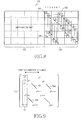
element 130 blocks the element 128 from the effects of the other rows. In this context, a description will now be made of a method of eliminating a coded bit being '1' in a column of degree '1'. - FIG. 9 illustrates the structure of the parity part of a parity check matrix according to an embodiment of the present invention. The information part of the parity check matrix is not shown here because it is not related to the subject matter of the present invention.
- Referring to FIG. 9, the parity part comprises shifted identity matrices σj on
diagonals 50, 50a and 50b and zero matrices elsewhere. j is an integer between 0 and 2(r-1) where r is (n-k). Shifted identity matrices witheven shift indexes second diagonals odd shift indexes - Particularly, matrices each containing only one element of 1 (hereinafter, referred to as delta matrices δi) are inserted into a
subblock column 54 including a column ofdegree 1. The delta matrices δi are of size PxP like the shifted identity matrices and every delta matrix has 1 at an ith bit of the first column. Here, i is an integer between 0 and (P-1) and δ-1 is a zero matrix. A 4x4 δi is
- Considering that the size of the parity part is (N-K)x(N-K), n=N/P and k=K/P, the
subblock column 54 includes (n-k-2) delta matrices. (n-k-2) is an odd number and the positions of the delta matrices are randomly decided. - Summing the rows of the above matrix column by column results in only the element corresponding to the first parity bit is 1 and the other elements are 0s. Hence, as described earlier, the parity bits can be encoded sequentially.
- FIG. 10 illustrates a LDPC code and the associated LDPC coding according to an embodiment of the present invention. Numerals written in small squares representing elements denote the sequence of encoding parity bits.
- Referring to FIG. 10, a
parity check matrix 140, H has aninformation part 142, H1 and aparity part 144, HP (H=[H1:HP]).Twodiagonals parity part 144. Afirst subblock column 150 of theparity part 144 has two shiftedidentity matrices - As stated before, the vector of the column-by-column sums of the rows in the
parity check matrix 140, H is given as S=[S1:SP]. Clearly,
element 146 according to

element 148. One thing to be noted is that the parity bits corresponding to the column containing an element of 1 in the delta matrix of the subblock 152 are encoded by considering p0 additionally. Let the parity bits ordered in the coding order be denoted by p0', p1', ..., p(N-K-1)' and rows reordered according to the order of pt' be denoted by ht'. Then, the parity bits are encoded by
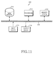
- FIG. 11 is a block diagram of a LDPC code generating apparatus according to an embodiment of the present invention.
- Referring to FIG. 11, a
computer system 200 comprises aprocessor 212 connected to amemory system 218 via asystem bus 230. Theprocessor 212 reads necessary parameters from thememory system 218, generates a LDPC code using the parameters, and stores the LDPC code in thememory system 218. For generation of the LDPC code, theprocessor 212 may be connected to amain memory 210, aninput device 214, and anoutput device 216 via thesystem bus 230. - A user enters a command to the
processor 212 via thesystem bus 230 by manipulating theinput device 214. Theprocessor 212 operates according to the command signal and displays the operation result to the user via theoutput device 216. The operation result may be stored in thememory system 218 upon user request. - The LDPC generating operation according to this embodiment of the present invention is implemented by storing known corresponding computer programs codes in the
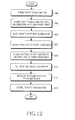
memory system 218 or designing corresponding hardware logic. The parameters needed for generation of the LDPC code or programs codes needed to calculate the parameters are stored in thememory system 218. The LDPC code generated by theprocessor 212 is stored in thememory system 218 on a subblock-by-subblock basis. - FIG. 12 is a flowchart illustrating a LDPC code generating operation according to an embodiment of the present invention. The LDPC code generating operation generates a parity check matrix that defines a LDPC code.
- Referring to FIG. 12, a parity check matrix is formed which comprises (N-K) rows for check nodes and N columns for variable nodes in order to encode an information sequence of length K to a codeword of length N in
step 300. The parity check matrix is divided into an information part matrix with K columns and a parity part matrix with (N-K) columns instep 302. Instep 304, the parity part matrix is further divided into PxP subblocks. P is a divisor of (N-K). Hence, the parity part matrix has (N-K)/P=(n-k) subblock rows and (n-k) subblock columns. - In
step 306, first and second diagonals are determined. The first diagonal runs from the first subblock row and subblock column to the last subblock row and subblock column, and the second diagonal is a shift of the first diagonal by f subblocks. Shifted identity matrices with predetermined shift indexes ji are placed in the subblocks on the first and second diagonals instep 308. f and ji are determined such that the coding performance of the parity check matrix is maximized. Compared to a conventional GDM LDPC code, none of the elements on the first and second diagonals are punctured. - In
step 310, zero matrices are filled elsewhere. An odd number of zero matrices in a subblock column comprising a column ofdegree 1 are replaced with delta matrices in the parity part matrix instep 312. As described before, the delta matrices are defined as matrices each containing 1 at only one entry and 0s elsewhere. The parity check matrix is stored in the memory system instep 314. - FIG. 13 illustrates an exemplary realization of the parity part of an LDPC code according to the preferred embodiment of the present invention.
- Referring to FIG. 13, subblocks on dual diagonals are all identity matrices I in a parity part HP. There are one delta matrix δ0 and one shifted identity matrix δs in two subblocks of the first subblock column. δs is a matrix shifted from the identity matrix by s. In this manner, insertion of the delta matrix δ0 in the first subblock column eliminates the column of
degree 1, thereby facilitating LDPC coding. Here, s is prime with P denoting a subblock size. This LDPC code offers the benefits of a very simple parity structure and very regular coding of parity bits. - For s=1, the coding order is given as

- FIG. 14 illustrates a parity check matrix with P=3 according to an embodiment of the present invention.
- Referring to FIG. 14, a
parity check matrix 160 has aninformation part 162 and aparity part 164. In theparity part 164, 3x3 identity matrices are placed ondual diagonals identity matrix 168 and adelta matrix 166 with only one element of 1. - The above-described systematic LDPC code has subblocks of shifted identity matrices and subblocks of delta matrices (i.e. delta blocks). The memory system preserves the parameters needed to represent the block LDPC code, that is, information about the degree of every check node, the degree of every variable node, the positions of non-zero matrices in every row, and the shift index s of every non-zero matrix. These parameters are expressed as positive integers. According to an embodiment of the present invention, the memory system stores the delta blocks discriminately from the other subblocks.
- In an embodiment of the present invention, the memory system manages 1-bit subblock information indicating whether each subblock being a non-zero matrix comprises a delta matrix or a shifted identity matrix. s represents a shift index for a subblock with a shifted identity matrix, and s also represents the position of 1 for a subblock with a delta matrix.
- In another embodiment of the present invention, the memory system indicates using s whether a subblock being a non-zero matrix includes a delta matrix. Since 0≤s<P, b=[log2P] bits are required to represent s. Here, [ ] is a ceiling function. Accordingly, the memory system allocates as many bits as b or more bits than b to s and represents delta blocks by s being equal to or greater than P.
- The parity check matrix is retrieved from the memory system to a LDPC encoder/decoder. The LDPC encoder computes a parity sequence Cp by Eq. (12) using an input information sequence C1 and the parity check matrix and concatenates C1 and CP into a codeword C. The codeword is transmitted to a receiver through a modulator and a radio frequency (RF) unit.
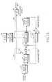
- With reference to FIG. 15, the configuration of an apparatus for decoding a block LDPC code using a parity check matrix according to a preferred embodiment of the present invention will be described below.
- Referring to FIG. 15, the LDPC decoding apparatus comprises a
block controller 410, avariable node part 400, anadder 415, adeinterleaver 417, aninterleaver 419, acontroller 421, amemory 423, anadder 425, acheck node part 450, and a hard-decision decoder 429. Thevariable node part 400 comprises avariable node processor 411 andswitches check node part 450 comprises acheck node processor 427. Thememory 423 represents a parity check matrix using the degree of every check node, the degree of every variable node, the positions of non-zero matrices in every row, and the shift indexes s of the non-zero matrices. Thememory 423 may further comprise 1-bit subblock information for indicating whether each subblock being a non-zero matrix comprises a delta matrix or a shifted identity matrix. - In operation, the
block controller 410 determines the block size of a signal received on a radio channel. In the presence of an information word part punctured in an LDPC coding apparatus corresponding to the LDPC decoding apparatus, theblock controller 410 controls the total block size by inserting 0s in the punctured positions. - The
variable node processor 411 calculates the probabilities of the signal received from theblock controller 410, and updates existing probabilities with the calculated probabilities. Here, thevariable node processor 411 connects the variable nodes to the check nodes in accordance with the predetermined parity check matrix and performs an update operation with as many input values as the number of check nodes connected to every variable node, and a corresponding output value. The number of check nodes connected to every variable node is equal to the weight (i.e. degree) of every column of the parity check matrix, that is, the number of 1s in every column. Thus, thevariable node processor 411 operates according to the weight of each column in the parity check matrix. When theswitch 413 is disabled, theswitch 414 switches the output of thevariable node processor 411 to theadder 415. - The
adder 415 subtracts the output of theinterleaver 419 generated in the previous iteration decoding cycle from the output of thevariable node processor 411. In an initial decoding cycle, the interleaver output is considered to be 0. - The
deinterleaver 417 deinterleaves the difference signal received from theadder 415 in a predetermined method. Thedeinterleaver 417 is configured in accordance with the parity check matrix because theinterleaver 419 corresponding to thedeinterleaver 417 operates in a different manner depending on the positions of elements of 1. - The
adder 425 subtracts the output of thecheck node processor 427 generated in the previous iterative decoding cycle from the output of thedeinterleaver 417. Thecheck node processor 427 connects the check nodes to the variable nodes in accordance with the parity check matrix and performs an update operation with as many input values as the number of variable nodes connected to every check node, and a corresponding output value. The number of variable nodes connected to every check node is equal to the weight of every row in the parity check matrix. Therefore, thecheck node processor 427 operates in accordance with the weight of the rows of the parity check matrix. - The
interleaver 419 interleaves the signal received from theadder 425 in a predetermined interleaving method under the control of thecontroller 421. Thecontroller 421 reads interleaving information from thememory 423 and controls the interleaving operation of theinterleaver 419 based on the interleaving information. Obviously, the output of thedeinterleaver 417 is considered to be 0 in the initial decoding cycle. - The above decoding operation is iteratively performed. After a predetermined number of decoding iterations, the
switch 414 switches off thevariable node processor 411 from theadder 415, and theswitch 413 switches thevariable node processor 411 to the hard-decision decoder 429. The hard-decision decoder 429 performs a hard decision on the signal received from thevariable node processor 411 and outputs the hard decision value as final decoded bits. - It can be further contemplated as another embodiment of the present invention that upon completion of variable node processing and check node processing on the signal received from the
block controller 410, theswitch 413 switches the output of thevariable node processor 411 to the hard-decision decoder 429. The hard decision value from the hard-decision decoder 429 is buffered in a buffer (not shown) and a parity checker (not shown) performs a parity check on the hard decision value. Thecontroller 421 may perform theparity check 421. If the parity check fails, the parity checker notifies thecontroller 421 of a need for further iterative decoding, and thus the signal from theblock controller 410 is again subject to variable node processing and check node processing. On the other hand, if the parity check passes, the buffered hard decision value is finally output as decoded bits. - The present invention operating as described above presents the following major effects.
- The present invention applies density evolution to coding of all parity bits by avoiding the presence of a variable node of
degree 1 for a GDM LDPC code, thereby increasing coding performance. Also, the LDPC code is represented while maintaining its block structure and saving memory capacity. As a result, efficient LDPC coding is carried out. - While the invention has been shown and described with reference to certain embodiments thereof, it will be understood by those skilled in the art that various changes in form and details may be made therein without departing from the spirit and scope of the invention as defined by the appended claims.
Claims (17)
- A method of generating a low density parity check (LDPC) code, comprising the steps of:(1) forming a parity check matrix having (N-K) rows for check nodes and N columns for variable nodes to encode an information sequence of length K to a codeword of length N;(2) dividing the parity check matrix into an information part matrix having K columns and a parity part matrix having (N-k) columns;(3) dividing the parity part matrix into PxP subblocks, P being a divisor of (N-K);(4) defining a first diagonal and a second diagonal in the parity part matrix, the second diagonal being a shift of the first diagonal by f subblocks;(5) placing shifted identity matrices with shift indexes in subblocks that lie on the first and second diagonals;(6) filling zero matrices in the remaining subblocks other than the subblocks of the first and second diagonals;(7) placing an odd number of delta matrices in one subblock column of the parity part matrix, each delta matrix comprising one element of 1 and the other elements of 0; and(8) storing the parity check matrix.
- The method of claim 1, wherein the step of (4) comprises the step of defining the first diagonal so that the first diagonal starts with a first subblock row and a first subblock column and ends with a last subblock row and a last subblock column.
- The method of claim 1, wherein the sum module P of the shift indexes of the shifted identity matrices on the first and second diagonals is prime with P.
- The method of claim 1, wherein the step of (7) comprises the step of substituting one zero matrix in the first subblock column of the parity part matrix into a delta matrix.
- The method of claim 1, wherein the delta matrices each have one element of 1 in a first column.
- The method of claim 1, wherein the step of (8) comprises the step of storing information about the degree of each check node, the degree of each variable node, the positions of non-zero matrices in each row, and the shift indexes of each non-zero matrix, and the 1-bit subblock information indicating whether the each non-zero matrix is a delta matrix or not.
- The method of claim 6, wherein the shift index of a non-zero matrix being a delta matrix indicates the position of an element of 1 in the delta matrix.
- The method of claim 1, wherein the step of (8) comprises the step of storing information on the degree of each check node, the degree of each variable node, the positions of non-zero matrices in each row, and the shift indexes of each non-zero matrix, the shift index of a non-zero matrix being a delta matrix being equal to or less than P.
- An apparatus for generating a low density parity check (LDPC) code, comprising:a memory system for storing program codes used to generate a parity check matrix defining the LDPC code, and storing the parity check matrix; anda processor for generating the parity check matrix by implementing the program codes,wherein the processor is adapted to perform the steps of:(a) forming a parity check matrix having (N-K) rows for check nodes and N columns for variable nodes to encode an information sequence of length K to a codeword of length N;(b) dividing the parity check matrix into an information part matrix having K columns and a parity part matrix having (N-k) columns;(c) dividing the parity part matrix into subblocks each being of size PxP where P is a divisor of (N-K);(d) defining a first diagonal and a second diagonal in the parity part matrix, the second diagonal being a shift of the first diagonal by f subblocks;(e) placing shifted identity matrices with shift indexes in subblocks that lie on the first and second diagonals;(f) filling zero matrices in the remaining subblocks other than the subblocks of the first and second diagonals;(g) placing an odd number of delta matrices in one subblock column of the parity part matrix, each delta matrix comprising one element of 1 and the other elements of 0; and(h) storing the parity check matrix.
- The apparatus of claim 9, wherein the first diagonal starts with a first subblock row and a first subblock column and ends with a last subblock row and a last subblock column.
- The apparatus of claim 9, wherein the sum module P of the shift indexes of the shifted identity matrices on the first and second diagonals is prime with P.
- The apparatus of claim 9, wherein in the step of (g), the processor substitutes one zero matrix in the first subblock column of the parity part matrix into a delta matrix.
- The apparatus of claim 9, wherein the delta matrices each have one element of 1 in a first column.
- The apparatus of claim 9, wherein the memory system comprises the parity check matrix using information on the degree of each check node, the degree of each variable node, the positions of non-zero matrices in each row, and the shift indexes of each non-zero matrix, and the 1-bit subblock information indicating whether the each non-zero matrix is a delta matrix or not.
- The apparatus of claim 14, wherein the shift index of a non-zero matrix being a delta matrix indicates the position of an element of 1 in the delta matrix.
- The apparatus of claim 9, wherein the memory system comprises the parity check matrix using information on the degree of each check node, the degree of each variable node, the positions of non-zero matrices in each row, and the shift indexes of each non-zero matrix, the shift index of a non-zero matrix being a delta matrix being equal to or less than P.
- A low density parity check (LDPC) coding method comprising the steps of:receiving an information sequence;encoding an information sequence of length K to a codeword of length N using an (N, K) parity check matrix having an information part matrix with (N-K) rows and K columns and a parity part matrix with K rows and K columns; andtransmitting the codeword to a receiver,wherein the parity check matrix is a set of subblocks and comprises a matrix having one element of 1 in at least one of the subblocks so that no columns of degree 1 exist in the parity check matrix.
Applications Claiming Priority (1)
| Application Number | Priority Date | Filing Date | Title |
|---|---|---|---|
| KR1020040100039A KR100913876B1 (en) | 2004-12-01 | 2004-12-01 | Method and apparatus for generating low density parity check codes |
Publications (2)
| Publication Number | Publication Date |
|---|---|
| EP1667328A1 true EP1667328A1 (en) | 2006-06-07 |
| EP1667328B1 EP1667328B1 (en) | 2007-10-10 |
Family
ID=35754942
Family Applications (1)
| Application Number | Title | Priority Date | Filing Date |
|---|---|---|---|
| EP05025980A Expired - Fee Related EP1667328B1 (en) | 2004-12-01 | 2005-11-29 | Method and apparatus for generating a low-density parity check (LDPC) code |
Country Status (7)
| Country | Link |
|---|---|
| US (1) | US7536623B2 (en) |
| EP (1) | EP1667328B1 (en) |
| JP (1) | JP4168055B2 (en) |
| KR (1) | KR100913876B1 (en) |
| CN (1) | CN100505556C (en) |
| AU (1) | AU2005239662B2 (en) |
| DE (1) | DE602005002815T2 (en) |
Cited By (6)
| Publication number | Priority date | Publication date | Assignee | Title |
|---|---|---|---|---|
| GB2439986A (en) * | 2006-07-07 | 2008-01-16 | Siemens Ag | Method for generating Low Density Parity Check (LDPC) codes and apparatus using the LDPC codes |
| GB2459828A (en) * | 2007-03-27 | 2009-11-11 | Lg Electronics Inc | Method of encoding data using a low density parity check code |
| US8196012B2 (en) | 2009-10-05 | 2012-06-05 | The Hong Kong Polytechnic University | Method and system for encoding and decoding low-density-parity-check (LDPC) codes |
| RU2461962C2 (en) * | 2008-05-14 | 2012-09-20 | Зти Корпорейшн | Method and apparatus for decoding low-density generator matrix code |
| RU2461963C2 (en) * | 2008-04-30 | 2012-09-20 | ЗетТиИ Корпорейшн | Method and apparatus for decoding low-density generator matrix code |
| CN111641575A (en) * | 2020-04-26 | 2020-09-08 | 北京邮电大学 | Orthogonal time-frequency two-dimensional space modulation signal receiving method and receiver |
Families Citing this family (40)
| Publication number | Priority date | Publication date | Assignee | Title |
|---|---|---|---|---|
| KR100641052B1 (en) * | 2004-12-08 | 2006-11-02 | 한국전자통신연구원 | LDPC encoder and decoder, and method for LDPC encoding and decoding |
| US7707479B2 (en) | 2005-12-13 | 2010-04-27 | Samsung Electronics Co., Ltd. | Method of generating structured irregular low density parity checkcodes for wireless systems |
| JP5215537B2 (en) * | 2006-06-28 | 2013-06-19 | 三星電子株式会社 | Information encoding apparatus, information decoding apparatus, information encoding method, and information decoding method |
| KR100837730B1 (en) | 2006-09-29 | 2008-06-13 | 한국전자통신연구원 | Method for reduced complexity encoder generating low density parity check codes |
| CN100596029C (en) * | 2006-10-20 | 2010-03-24 | 北京泰美世纪科技有限公司 | Method of constructing check matrix for LDPC code, and encoding and decoding device of using the method |
| US7913149B2 (en) * | 2006-12-20 | 2011-03-22 | Lsi Corporation | Low complexity LDPC encoding algorithm |
| US20100107033A1 (en) * | 2007-01-31 | 2010-04-29 | Kenichi Kuri | Radio communication device and puncturing method |
| KR101370903B1 (en) | 2007-03-16 | 2014-03-10 | 엘지전자 주식회사 | Method of encoding and decoding data using LDPC code |
| WO2008117994A1 (en) * | 2007-03-27 | 2008-10-02 | Lg Electronics Inc. | Method of encoding data using a low density parity check code |
| KR100975696B1 (en) * | 2007-04-05 | 2010-08-12 | 삼성전자주식회사 | Apparatus and method for encoding in a communication system |
| US8418023B2 (en) | 2007-05-01 | 2013-04-09 | The Texas A&M University System | Low density parity check decoder for irregular LDPC codes |
| US20090013239A1 (en) * | 2007-07-02 | 2009-01-08 | Broadcom Corporation | LDPC (Low Density Parity Check) decoder employing distributed check and/or variable node architecture |
| CN101373976A (en) * | 2007-08-23 | 2009-02-25 | 松下电器产业株式会社 | Method and equipment for generating LDPC check matrix |
| US7911364B1 (en) | 2007-09-04 | 2011-03-22 | Marvell International Ltd. | Interleaver for turbo equalization |
| EP3614567B1 (en) | 2007-09-28 | 2023-12-20 | Panasonic Holdings Corporation | Encoding method, encoder, and decoder |
| CN101414833B (en) * | 2007-10-19 | 2010-08-04 | 中兴通讯股份有限公司 | Method and apparatus for encoding low-density generated matrix code |
| US8327215B2 (en) | 2007-12-13 | 2012-12-04 | Electronics And Telecommunications Research Institute | Apparatus and method for encoding LDPC code using message passing algorithm |
| KR101431268B1 (en) * | 2007-12-14 | 2014-08-20 | 삼성전자주식회사 | Apparatus and method for generating low density parity check codes for sequential decoding algorithm |
| CN101471672B (en) * | 2007-12-27 | 2011-04-13 | 华为技术有限公司 | Method for generating check matrix and corresponding encoding method and encoder |
| CN101946414B (en) * | 2008-02-18 | 2013-08-14 | 三星电子株式会社 | Apparatus and method for encoding and decoding channel in communication system using low-density parity-check codes |
| PL2091156T3 (en) | 2008-02-18 | 2014-01-31 | Samsung Electronics Co Ltd | Apparatus and method for channel encoding and decoding in a communication system using low-density parity-check codes |
| CN101286819B (en) * | 2008-05-07 | 2010-05-12 | 中兴通讯股份有限公司 | Data receiving method and device |
| JP5009418B2 (en) * | 2008-06-09 | 2012-08-22 | パイオニア株式会社 | Parity matrix generation method, parity check matrix, decoding apparatus, and decoding method |
| WO2010006430A1 (en) * | 2008-07-15 | 2010-01-21 | The Royal Institution For The | Decoding of linear codes with parity check matrix |
| US8219873B1 (en) | 2008-10-20 | 2012-07-10 | Link—A—Media Devices Corporation | LDPC selective decoding scheduling using a cost function |
| TWI427936B (en) * | 2009-05-29 | 2014-02-21 | Sony Corp | Receiving apparatus, receiving method, program, and receiving system |
| GB2471513B (en) * | 2009-07-02 | 2013-09-25 | Samsung Electronics Uk Ltd | Encoding/decoding apparatus and method |
| EP2348487A3 (en) | 2010-01-22 | 2017-09-13 | Samsung Electronics Co., Ltd. | Method and apparatus for creating animation message |
| CN102859885B (en) * | 2010-04-09 | 2015-10-07 | Sk海尼克斯存储技术公司 | The realization of LDPC selectivity decoding scheduling |
| KR20110114204A (en) * | 2010-04-13 | 2011-10-19 | 삼성전자주식회사 | Ldpc encoding method and ldpc encoder |
| CN102790622B (en) * | 2011-05-19 | 2017-03-15 | 中兴通讯股份有限公司 | The building method and device of low-density parity check code check matrix |
| KR101685010B1 (en) * | 2012-06-01 | 2016-12-13 | 한국전자통신연구원 | Low density parity check code for terrestrial cloud trasmission |
| KR102178262B1 (en) * | 2014-07-08 | 2020-11-12 | 삼성전자주식회사 | Parity check matrix generating method, encoding apparatus, encoding method, decoding apparatus and encoding method using the same |
| WO2018111129A1 (en) * | 2016-12-13 | 2018-06-21 | Huawei Technologies Co., Ltd | Devices and methods for generating a low density parity check code for a incremental redundancy harq communication apparatus |
| CN108322285B (en) * | 2017-01-16 | 2020-09-18 | 华为技术有限公司 | Data sending method, receiving method and device |
| US11043970B2 (en) * | 2017-02-06 | 2021-06-22 | Lg Electronics Inc. | Method for transmitting LDPC code using row-orthogonal and apparatus therefor |
| EP3588786B1 (en) * | 2017-06-15 | 2022-11-16 | Huawei Technologies Co., Ltd. | Qc-ldpc codes for 3gpp 5g mobile radio |
| KR102059002B1 (en) * | 2017-06-25 | 2019-12-24 | 엘지전자 주식회사 | Method for performing encoding based on parity check matrix of LDPC code in wireless communication system and terminal using same |
| CN109327225B9 (en) | 2017-06-27 | 2021-12-10 | 华为技术有限公司 | Information processing method and device and communication equipment |
| CN114222132A (en) * | 2022-01-13 | 2022-03-22 | 北京达佳互联信息技术有限公司 | Video decoding inverse transformation method and device |
Citations (3)
| Publication number | Priority date | Publication date | Assignee | Title |
|---|---|---|---|---|
| US20040093549A1 (en) * | 2002-11-07 | 2004-05-13 | Hongwei Song | Encoding method using a low density parity check code with a column weight of two |
| US20040153934A1 (en) * | 2002-08-20 | 2004-08-05 | Hui Jin | Methods and apparatus for encoding LDPC codes |
| EP1596501A1 (en) * | 2004-05-12 | 2005-11-16 | Samsung Electronics Co., Ltd. | Apparatus and method for encoding and decoding block low density parity check codes with a variable coding rate |
Family Cites Families (9)
| Publication number | Priority date | Publication date | Assignee | Title |
|---|---|---|---|---|
| FR2799592B1 (en) | 1999-10-12 | 2003-09-26 | Thomson Csf | SIMPLE AND SYSTEMATIC CONSTRUCTION AND CODING METHOD OF LDPC CODES |
| US6567465B2 (en) * | 2001-05-21 | 2003-05-20 | Pc Tel Inc. | DSL modem utilizing low density parity check codes |
| US7000168B2 (en) * | 2001-06-06 | 2006-02-14 | Seagate Technology Llc | Method and coding apparatus using low density parity check codes for data storage or data transmission |
| US6633856B2 (en) * | 2001-06-15 | 2003-10-14 | Flarion Technologies, Inc. | Methods and apparatus for decoding LDPC codes |
| US6948109B2 (en) * | 2001-10-24 | 2005-09-20 | Vitesse Semiconductor Corporation | Low-density parity check forward error correction |
| KR100936022B1 (en) * | 2002-12-21 | 2010-01-11 | 삼성전자주식회사 | Method of generating parity information for error-correction and apparatus thereof |
| KR100996029B1 (en) * | 2003-04-29 | 2010-11-22 | 삼성전자주식회사 | Apparatus and method for coding of low density parity check code |
| KR100809619B1 (en) * | 2003-08-26 | 2008-03-05 | 삼성전자주식회사 | Apparatus and method for coding/decoding block low density parity check code in a mobile communication system |
| US7260763B2 (en) * | 2004-03-11 | 2007-08-21 | Nortel Networks Limited | Algebraic low-density parity check code design for variable block sizes and code rates |
-
2004
- 2004-12-01 KR KR1020040100039A patent/KR100913876B1/en active IP Right Grant
-
2005
- 2005-11-29 DE DE602005002815T patent/DE602005002815T2/en active Active
- 2005-11-29 EP EP05025980A patent/EP1667328B1/en not_active Expired - Fee Related
- 2005-11-29 JP JP2005344040A patent/JP4168055B2/en not_active Expired - Fee Related
- 2005-11-29 AU AU2005239662A patent/AU2005239662B2/en not_active Ceased
- 2005-11-30 US US11/289,300 patent/US7536623B2/en active Active
- 2005-12-01 CN CNB200510127295XA patent/CN100505556C/en not_active Expired - Fee Related
Patent Citations (3)
| Publication number | Priority date | Publication date | Assignee | Title |
|---|---|---|---|---|
| US20040153934A1 (en) * | 2002-08-20 | 2004-08-05 | Hui Jin | Methods and apparatus for encoding LDPC codes |
| US20040093549A1 (en) * | 2002-11-07 | 2004-05-13 | Hongwei Song | Encoding method using a low density parity check code with a column weight of two |
| EP1596501A1 (en) * | 2004-05-12 | 2005-11-16 | Samsung Electronics Co., Ltd. | Apparatus and method for encoding and decoding block low density parity check codes with a variable coding rate |
Non-Patent Citations (3)
| Title |
|---|
| MACKAY D.J.C. ET AL.: "Comparison of constructions of irregular Gallager codes", IEEE TRANSACTIONS ON COMMUNICATIONS, vol. 47, no. 10, October 1999 (1999-10-01), pages 1449 - 1454, XP002368050 * |
| MILENKOVIC O.: "Block-circulant low-density parity-check codes for optical communication systems", IEEE JOURNAL F SELECTED TOPICS IN QUANTUM ELECTRONICS, vol. 10, no. 2, March 2004 (2004-03-01), pages 294 - 299, XP002368049 * |
| TANNER R.M. ET AL.: "LDPC block and convolutional codes based on circulant matrices", IEEE TRANSACTION ON INFORMATION THEORY, vol. 50, no. 12, December 2004 (2004-12-01), pages 2966 - 2984, XP002368048, Retrieved from the Internet <URL:http://ieeexplore.ieee.org/iel5/18/29865/01362891.pdf?tp=&arnumber=1362891&isnumber=29865> [retrieved on 20051216] * |
Cited By (10)
| Publication number | Priority date | Publication date | Assignee | Title |
|---|---|---|---|---|
| GB2439986A (en) * | 2006-07-07 | 2008-01-16 | Siemens Ag | Method for generating Low Density Parity Check (LDPC) codes and apparatus using the LDPC codes |
| GB2439986B (en) * | 2006-07-07 | 2008-05-21 | Siemens Ag | Method for generating LDPC codes and apparatus using the LDPC codes |
| GB2459828A (en) * | 2007-03-27 | 2009-11-11 | Lg Electronics Inc | Method of encoding data using a low density parity check code |
| GB2459828B (en) * | 2007-03-27 | 2010-11-24 | Lg Electronics Inc | Method of encoding data using a low density parity check code |
| RU2461963C2 (en) * | 2008-04-30 | 2012-09-20 | ЗетТиИ Корпорейшн | Method and apparatus for decoding low-density generator matrix code |
| RU2461962C2 (en) * | 2008-05-14 | 2012-09-20 | Зти Корпорейшн | Method and apparatus for decoding low-density generator matrix code |
| US8438448B2 (en) | 2008-05-14 | 2013-05-07 | Zte Corporation | Decoding method and device for low density generator matrix codes |
| US8196012B2 (en) | 2009-10-05 | 2012-06-05 | The Hong Kong Polytechnic University | Method and system for encoding and decoding low-density-parity-check (LDPC) codes |
| CN111641575A (en) * | 2020-04-26 | 2020-09-08 | 北京邮电大学 | Orthogonal time-frequency two-dimensional space modulation signal receiving method and receiver |
| CN111641575B (en) * | 2020-04-26 | 2022-01-18 | 北京邮电大学 | Orthogonal time-frequency two-dimensional space modulation signal receiving method and receiver |
Also Published As
| Publication number | Publication date |
|---|---|
| US7536623B2 (en) | 2009-05-19 |
| EP1667328B1 (en) | 2007-10-10 |
| CN1783730A (en) | 2006-06-07 |
| CN100505556C (en) | 2009-06-24 |
| AU2005239662B2 (en) | 2008-04-03 |
| KR100913876B1 (en) | 2009-08-26 |
| AU2005239662A1 (en) | 2006-06-15 |
| DE602005002815T2 (en) | 2008-07-17 |
| JP4168055B2 (en) | 2008-10-22 |
| DE602005002815D1 (en) | 2007-11-22 |
| JP2006157926A (en) | 2006-06-15 |
| US20060156183A1 (en) | 2006-07-13 |
| KR20060061145A (en) | 2006-06-07 |
Similar Documents
| Publication | Publication Date | Title |
|---|---|---|
| EP1667328B1 (en) | Method and apparatus for generating a low-density parity check (LDPC) code | |
| KR100678175B1 (en) | Apparatus and method for coding/decoding block low density parity check code with variable block length | |
| US8341492B2 (en) | Quasi-cyclic LDPC (low density parity check) code construction | |
| JP4555334B2 (en) | Apparatus and method for encoding / decoding block low density parity check code having variable block length | |
| KR100739510B1 (en) | Apparatus and method for coding/decoding semi-systematic block low density parity check code | |
| JP4555333B2 (en) | Apparatus and method for encoding / decoding block low density parity check code having variable coding rate | |
| US9319068B2 (en) | Apparatus and method for coding/decoding block low density parity check code in a mobile communication system | |
| KR100713371B1 (en) | Apparatus and method for encoding/decoding a block low density parity check code | |
| KR100641052B1 (en) | LDPC encoder and decoder, and method for LDPC encoding and decoding | |
| KR100809616B1 (en) | Apparatus and method for coding/decoding block low density parity check code with variable block length | |
| KR101208547B1 (en) | Method of encoding and decoding using ldpc code | |
| EP1829223A2 (en) | Apparatus and method for decoding using channel code | |
| US8112695B2 (en) | Method for encoding data message K' for transmission from sending station to receiving station as well as method for decoding, sending station, receiving station and software | |
| KR101216075B1 (en) | Apparatus and method for decoding using channel code | |
| KR101147768B1 (en) | Apparatus and method for decoding using channel code | |
| KR20060016059A (en) | Apparatus and method for coding/decoding block low density parity check code with variable block length | |
| KR20060016061A (en) | Apparatus and method for coding/decoding block low density parity check code with variable block length |
Legal Events
| Date | Code | Title | Description |
|---|---|---|---|
| PUAI | Public reference made under article 153(3) epc to a published international application that has entered the european phase |
Free format text: ORIGINAL CODE: 0009012 |
|
| 17P | Request for examination filed |
Effective date: 20051129 |
|
| AK | Designated contracting states |
Kind code of ref document: A1 Designated state(s): AT BE BG CH CY CZ DE DK EE ES FI FR GB GR HU IE IS IT LI LT LU LV MC NL PL PT RO SE SI SK TR |
|
| AX | Request for extension of the european patent |
Extension state: AL BA HR MK YU |
|
| 17Q | First examination report despatched |
Effective date: 20060913 |
|
| AKX | Designation fees paid |
Designated state(s): DE FR GB IT |
|
| GRAP | Despatch of communication of intention to grant a patent |
Free format text: ORIGINAL CODE: EPIDOSNIGR1 |
|
| RIC1 | Information provided on ipc code assigned before grant |
Ipc: H03M 13/03 20060101ALI20070228BHEP Ipc: H03M 13/11 20060101AFI20070228BHEP |
|
| GRAS | Grant fee paid |
Free format text: ORIGINAL CODE: EPIDOSNIGR3 |
|
| GRAA | (expected) grant |
Free format text: ORIGINAL CODE: 0009210 |
|
| AK | Designated contracting states |
Kind code of ref document: B1 Designated state(s): DE FR GB IT |
|
| REG | Reference to a national code |
Ref country code: GB Ref legal event code: FG4D |
|
| REF | Corresponds to: |
Ref document number: 602005002815 Country of ref document: DE Date of ref document: 20071122 Kind code of ref document: P |
|
| ET | Fr: translation filed | ||
| PLBE | No opposition filed within time limit |
Free format text: ORIGINAL CODE: 0009261 |
|
| STAA | Information on the status of an ep patent application or granted ep patent |
Free format text: STATUS: NO OPPOSITION FILED WITHIN TIME LIMIT |
|
| 26N | No opposition filed |
Effective date: 20080711 |
|
| REG | Reference to a national code |
Ref country code: DE Ref legal event code: R082 Ref document number: 602005002815 Country of ref document: DE Representative=s name: GRUENECKER, KINKELDEY, STOCKMAIR & SCHWANHAEUS, DE Ref country code: DE Ref legal event code: R082 Ref document number: 602005002815 Country of ref document: DE Representative=s name: GRUENECKER PATENT- UND RECHTSANWAELTE PARTG MB, DE |
|
| REG | Reference to a national code |
Ref country code: FR Ref legal event code: PLFP Year of fee payment: 12 |
|
| REG | Reference to a national code |
Ref country code: FR Ref legal event code: PLFP Year of fee payment: 13 |
|
| REG | Reference to a national code |
Ref country code: FR Ref legal event code: PLFP Year of fee payment: 14 |
|
| PGFP | Annual fee paid to national office [announced via postgrant information from national office to epo] |
Ref country code: DE Payment date: 20181022 Year of fee payment: 14 |
|
| PGFP | Annual fee paid to national office [announced via postgrant information from national office to epo] |
Ref country code: IT Payment date: 20181113 Year of fee payment: 14 Ref country code: GB Payment date: 20181023 Year of fee payment: 14 Ref country code: FR Payment date: 20181029 Year of fee payment: 14 |
|
| REG | Reference to a national code |
Ref country code: DE Ref legal event code: R119 Ref document number: 602005002815 Country of ref document: DE |
|
| GBPC | Gb: european patent ceased through non-payment of renewal fee |
Effective date: 20191129 |
|
| PG25 | Lapsed in a contracting state [announced via postgrant information from national office to epo] |
Ref country code: IT Free format text: LAPSE BECAUSE OF NON-PAYMENT OF DUE FEES Effective date: 20191129 Ref country code: FR Free format text: LAPSE BECAUSE OF NON-PAYMENT OF DUE FEES Effective date: 20191130 Ref country code: DE Free format text: LAPSE BECAUSE OF NON-PAYMENT OF DUE FEES Effective date: 20200603 Ref country code: GB Free format text: LAPSE BECAUSE OF NON-PAYMENT OF DUE FEES Effective date: 20191129 |