EP1667180A1 - Electrical contactor and electric arc extinguishing chamber with deionisation blades - Google Patents
Electrical contactor and electric arc extinguishing chamber with deionisation blades Download PDFInfo
- Publication number
- EP1667180A1 EP1667180A1 EP05354038A EP05354038A EP1667180A1 EP 1667180 A1 EP1667180 A1 EP 1667180A1 EP 05354038 A EP05354038 A EP 05354038A EP 05354038 A EP05354038 A EP 05354038A EP 1667180 A1 EP1667180 A1 EP 1667180A1
- Authority
- EP
- European Patent Office
- Prior art keywords
- fins
- fin
- opening
- arc
- duct
- Prior art date
- Legal status (The legal status is an assumption and is not a legal conclusion. Google has not performed a legal analysis and makes no representation as to the accuracy of the status listed.)
- Granted
Links
Images


Classifications
-
- H—ELECTRICITY
- H01—ELECTRIC ELEMENTS
- H01H—ELECTRIC SWITCHES; RELAYS; SELECTORS; EMERGENCY PROTECTIVE DEVICES
- H01H9/00—Details of switching devices, not covered by groups H01H1/00 - H01H7/00
- H01H9/30—Means for extinguishing or preventing arc between current-carrying parts
- H01H9/34—Stationary parts for restricting or subdividing the arc, e.g. barrier plate
- H01H9/36—Metal parts
- H01H9/362—Mounting of plates in arc chamber
-
- H—ELECTRICITY
- H01—ELECTRIC ELEMENTS
- H01H—ELECTRIC SWITCHES; RELAYS; SELECTORS; EMERGENCY PROTECTIVE DEVICES
- H01H73/00—Protective overload circuit-breaking switches in which excess current opens the contacts by automatic release of mechanical energy stored by previous operation of a hand reset mechanism
- H01H73/02—Details
- H01H73/18—Means for extinguishing or suppressing arc
-
- H—ELECTRICITY
- H01—ELECTRIC ELEMENTS
- H01H—ELECTRIC SWITCHES; RELAYS; SELECTORS; EMERGENCY PROTECTIVE DEVICES
- H01H9/00—Details of switching devices, not covered by groups H01H1/00 - H01H7/00
- H01H9/30—Means for extinguishing or preventing arc between current-carrying parts
- H01H9/34—Stationary parts for restricting or subdividing the arc, e.g. barrier plate
- H01H2009/348—Provisions for recirculation of arcing gasses to improve the arc extinguishing, e.g. move the arc quicker into the arcing chamber
Abstract
Description
L'invention est relative à un dispositif électrique de coupure comportant un boîtier ayant un plan géométrique longitudinal de référence, une paire de contacts électriques séparables disposée dans un volume d'ouverture, une chambre d'extinction d'arc s'ouvrant sur le volume d'ouverture et étant délimitée par deux parois latérales parallèles et placées de part et d'autre du plan géométrique de référence, une paroi postérieure éloignée du volume d'ouverture, une paroi inférieure et une paroi supérieure. La chambre d'extinction d'arc comprend un empilement d'au moins deux d'ailettes de désionisation séparées les unes des autres par un espace d'échange, chaque ailette ayant une arête d'attaque destinée à être exposée à l'arc. Au moins un espace d'échange est relié à au moins un conduit d'évacuation via au moins un trou d'évacuation.The invention relates to an electrical cut-off device comprising a housing having a reference longitudinal geometric plane, a pair of separable electrical contacts disposed in an opening volume, an arc extinction chamber opening on the volume opening and being delimited by two parallel side walls and placed on either side of the geometric reference plane, a rear wall remote from the opening volume, a bottom wall and an upper wall. The arc extinguishing chamber comprises a stack of at least two deionization fins separated from each other by an exchange space, each fin having a leading edge to be exposed to the arc. At least one exchange space is connected to at least one evacuation duct via at least one evacuation hole.
La présence de défauts électriques à l'intérieur de dispositifs de coupure tel que des disjoncteurs, des interrupteurs ou contacteurs électriques provoque une brusque ouverture de leurs contacts électriques. Cette séparation rapide des contacts est généralement accompagnée de la naissance d'arc électrique. L'énergie de l'arc et les décharges de gaz accompagnant la naissance dudit arc donnent naissance à des contraintes importantes au niveau des mécanismes et risquent d'endommager le dispositif.The presence of electrical faults inside switching devices such as circuit breakers, switches or electrical contactors causes a sudden opening of their electrical contacts. This rapid separation of the contacts is usually accompanied by the birth of an electric arc. The energy of the arc and the gas discharges accompanying the birth of said arc give rise to significant constraints on the mechanisms and may damage the device.
Pour réduire temps de présence du courant de court-circuit et réduire par la sorte l'effort thermique supporté par le dispositif électrique de coupure, la tension d'arc est élevée le plus rapidement possible jusqu'à ce qu'elle devienne supérieure à la tension appliquée. Ceci provoque l'annulation du courant de court-circuit. La résistance diélectrique de l'air se trouvant entre les contacts séparés empêche alors un réamorçage ou d'autres éclatements d'arc.In order to reduce the time of occurrence of the short-circuit current and thus to reduce the thermal load borne by the electrical breaking device, the arc voltage is raised as rapidly as possible until it becomes greater than the applied voltage. This causes the cancellation of the short circuit current. The dielectric resistance of the air between the separated contacts then prevents a reboot or other arcing.
L'arc électrique doit être refroidi le plus rapidement possible tout en restant éloigné des contacts électriques. Ce refroidissement se fait couramment en plaçant l'arc à l'intérieur d'une chambre d'extinction d'arc comportant un empilement de plaques métalliques appelées ailettes de désionisation. En pratique, l'arc électrique, qui vient de naître, est poussé dans la chambre par des forces électrodynamiques induites par un champ magnétique du au courant circulant dans les conducteurs.The electric arc must be cooled as quickly as possible while remaining away from the electrical contacts. This cooling is commonly done by placing the arc inside an arc extinguishing chamber comprising a stack of metal plates called deionization fins. In practice, the electric arc, which has just been born, is pushed into the chamber by electrodynamic forces induced by a magnetic field of the current flowing in the conductors.
Lors de son déplacement, l'arc tend à se déplacer entre les parois latérales de la chambre d'extinction d'arc en empruntant généralement les évidements présents dans les ailettes. Ces évidements favorisent la migration de l'arc vers le fond de la chambre. En outre, l'empilement des ailettes provoque un découpage de l'arc et facilite son insertion dans la chambre d'extinction d'arc 10. Les ailettes offrent à l'arc une surface d'échange thermique durant toute la coupure. Au moment de la progression de l'arc dans la chambre, ce dernier tend à se dilater pour envahir tout l'espace disponible. Les ailettes contiennent cette dilatation en interagissant avec la périphérie de l'arc. La tension d'arc augmente au fur et à mesure que l'arc se refroidit. En outre, la pression dans le volume de coupure augmente fortement.During its movement, the arc tends to move between the side walls of the arc extinguishing chamber, generally borrowing the recesses present in the fins. These recesses favor the migration of the arc towards the bottom of the chamber. In addition, the stack of fins causes a cutting of the arc and facilitates its insertion into the
Si la forme des évidements n'est pas optimisée, on peut assister à des re-claquages répétitifs d'arc entre les contacts.If the shape of the recesses is not optimized, we can witness repetitive arc recoblings between the contacts.
Certains documents (FR2839195) divulguent des évidements se terminant par une cheminée qui tend à stabiliser l'arc dans une région éloignée du volume d'ouverture des contacts. Cependant, la forme de l'évidement caractérisée par la présence d'un couloir cheminant de la zone de naissance de l'arc à la cheminée peut entraîner un envoi de gaz chauds et de vapeurs en direction de la zone d'ouverture des contacts et ainsi provoquer une fuite de l'arc depuis la chambre vers les contacts. Cette fuite s'accompagne de re-claquages répétitifs.Some documents (FR2839195) disclose recesses terminating in a chimney which tends to stabilize the arc in a region remote from the opening volume of the contacts. However, the shape of the recess characterized by the presence of a corridor running from the birth zone of the arc to the chimney can cause a sending of hot gases and vapors towards the opening area of the contacts and thus causing a leak of the arc from the chamber to the contacts. This leak is accompanied by repetitive repetitions.
Par ailleurs, la naissance de l'arc entraîne concomitamment la naissance d'une importante quantité de vapeurs métalliques ou gaz, qui peuvent, s'elles ne sont pas évacuées, être responsables notamment d'un arc de liaison entre les phases du dispositif électrique de coupure et créer une explosion.Moreover, the birth of the arc causes concomitantly the birth of a large amount of metal vapor or gas, which may, if they are not evacuated, be responsible in particular for a connecting arc between the phases of the electrical device cut and create an explosion.
De nombreuses solutions existantes prévoient au moins un canal d'évacuation desdits gaz à l'extérieur de la zone proche des contacts. Ces gaz sont généralement expulsés à l'extérieur du dispositif électrique de coupure.Many existing solutions provide at least one exhaust channel for said gases outside the area near the contacts. These gases are generally expelled outside the electrical cut-off device.
Ces solutions bien que comportant des avantages peuvent tout de même générer des nuisances dans les locaux où sont placés les dispositifs de coupure. En effet, ces gaz étant encore chauds et fortement ionisés, peuvent provoquer des effets néfastes.These solutions, although having advantages, may nevertheless generate nuisances in the premises where the cut-off devices are placed. Indeed, these gases are still hot and strongly ionized, can cause adverse effects.
Afin d'éviter cette pollution de l'environnement extérieur, d'autres solutions proposent un recyclage de gaz en interne (GB2285889, US5731561, FR1400079).In order to avoid this pollution of the external environment, other solutions offer internal gas recycling (GB2285889, US5731561, FR1400079).
Ces solutions peuvent présenter certains inconvénients. Ce recyclage des gaz en interne s'accompagne généralement d'une augmentation du volume du dispositif électrique de coupure. En effet, les gaz sont généralement conduits dans des volumes spécifiques se trouvant au-delà de la chambre d'extinction d'arc. En outre, les canaux utilisés pour la conduite des gaz, peuvent, de part leur géométrie, induire des bouchons de pression responsables d'une mauvaise évacuation ou un ralentissement desdits gaz.These solutions may have certain disadvantages. This internal gas recirculation is generally accompanied by an increase in the volume of the electrical cut-off device. Indeed, the gases are generally conducted in specific volumes located beyond the arc extinction chamber. In addition, the channels used for the gas duct can, due to their geometry, induce pressure caps responsible for poor evacuation or slowing of said gases.
L'invention vise donc à remédier aux inconvénients de l'état de la technique, de manière à proposer un dispositif électrique de coupure comportant des ailettes de désionisation permettant un refroidissement rapide de l'arc électrique.The invention therefore aims to overcome the drawbacks of the state of the art, so as to provide an electrical cutoff device comprising deionization fins for rapid cooling of the electric arc.
L'arête libre d'attaque d'au moins deux des ailettes du dispositif selon l'invention délimite un évidement débouchant de forme asymétrique et formant deux branches latérales, ledit évidement étant réalisée de manière à créer, lorsque lesdites ailettes sont empilées en alternance, au moins une cheminée dont le conduit apparaît comme sensiblement fermé dans un plan perpendiculaire à l'axe longitudinal de ladite cheminée.The free edge of attack of at least two of the fins of the device according to the invention delimits a recess opening of asymmetrical shape and forming two lateral branches, said recess being made so as to create, when said fins are stacked alternately, at least one chimney whose duct appears as substantially closed in a plane perpendicular to the longitudinal axis of said chimney.
Avantageusement, le dispositif comprend selon l'axe z, au moins deux zones d'alignement entre une branche latérale d'une première ailette et au moins une branche latérale d'une seconde ailette ayant subi, par rapport à ladite première ailette, une rotation de 180° autour de son axe longitudinal.Advantageously, the device comprises, along the axis z, at least two alignment zones between a lateral branch of a first fin and at least one lateral branch of a second fin having undergone, with respect to said first fin, a rotation 180 ° around its longitudinal axis.
Dans un mode de réalisation préférentiel de l'invention, l'arête libre d'attaque des ailettes est en contact au moins deux fois avec l'axe longitudinal de desdites ailettes.In a preferred embodiment of the invention, the free edge of attack fins is in contact at least twice with the longitudinal axis of said fins.
Dans un mode de réalisation préférentiel de l'invention, l'arête libre d'attaque des ailettes coupe au moins deux fois l'axe longitudinal desdites ailettes.In a preferred embodiment of the invention, the free cutting edge of the fins cuts at least twice the longitudinal axis of said fins.
Avantageusement, le dispositif de coupure comprend, selon l'axe z, au moins une zone de recouvrement entre une branche latérale d'une première ailette et au moins une branche latérale d'une seconde ailette ayant subi, par rapport à ladite première ailette, une rotation de 180° autour de son axe longitudinal.Advantageously, the cut-off device comprises, along the z-axis, at least one overlap zone between a lateral branch of a first fin and at least one lateral branch of a second fin having undergone, with respect to said first fin, a rotation of 180 ° around its longitudinal axis.
De préférence, l'arête libre d'attaque de l'évidement délimite une première portion antérieure évasée débouchant sur le volume d'ouverture et une deuxième portion postérieure longitudinale s'étendant vers la paroi postérieure, la première portion antérieure évasée est coupée par l'axe longitudinal des ailettes.Preferably, the free leading edge of the recess delimits a first flared front portion opening on the opening volume and a second longitudinal posterior portion extending towards the posterior wall, the first flared front portion is cut by the longitudinal axis of the fins.
Selon un mode de développement de l'invention, chaque ailette est positionnée à coté d'une autre ailette ayant subi une rotation de 180° par rapport à son axe longitudinal.According to one embodiment of the invention, each fin is positioned next to another fin which has been rotated 180 ° relative to its longitudinal axis.
Selon un mode particulier de développement de l'invention, au moins un conduit d'évacuation s'étend d'au moins un trou d'évacuation vers une ouverture, le long d'au moins une paroi latérale, ledit conduit comportant, selon l'axe z de l'entrée des gaz à leur sortie dudit conduit, une section sensiblement constante ou croissante, ladite ouverture (18) étant au moins égale à la plus grande section dudit conduit et étant placée en vis à vis des contacts électriques du volume d'ouverture.According to a particular embodiment of the invention, at least one evacuation duct extends from at least one evacuation hole to an opening, along at least one side wall, said duct comprising, according to z axis of the gas inlet at their outlet of said duct, a substantially constant or increasing section, said opening (18) being at least equal to the largest section of said duct and being placed facing the electrical contacts of the volume opening.
De préférence, chaque espace d'échange de la chambre d'extinction comporte au moins un trou d'évacuation relié à au moins un conduit d'évacuation.Preferably, each exchange space of the extinguishing chamber comprises at least one evacuation hole connected to at least one evacuation duct.
De préférence, le dispositif comporte au moins deux conduits d'évacuation, au moins un conduit s'étendant le long de chaque paroi latérale de la chambre d'extinction d'arc.Preferably, the device comprises at least two exhaust ducts, at least one duct extending along each side wall of the arc extinguishing chamber.
Avantageusement, les espaces d'échange de la chambre d'extinction comportent au moins deux trous d'évacuation, au moins un trou étant relié à chacun des conduits d'évacuation s'étendant le long de chaque paroi.Advantageously, the exchange spaces of the extinguishing chamber comprise at least two evacuation holes, at least one hole being connected to each of the evacuation conduits extending along each wall.
De préférence, les trous d'évacuation sont placés dans une zone comprise entre la paroi postérieure et l'axe médian des ailettes.Preferably, the drain holes are placed in an area between the rear wall and the center axis of the fins.
Les trous d'évacuation sont placés dans les parois latérales.The drain holes are placed in the side walls.
Les trous d'évacuation sont placés dans la paroi postérieure.The drainage holes are placed in the posterior wall.
Les conduits d'évacuation ont une forme sensiblement parallélépipédique.The exhaust ducts have a substantially parallelepiped shape.
D'autres avantages et caractéristiques ressortiront plus clairement de la description qui va suivre d'un mode particulier de réalisation de l'invention, donné à titre d'exemple non limitatif, et représenté aux dessins annexés sur lesquels :
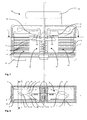
- la figure 1 représente une vue de coté d'un dispositif électrique de coupure selon un premier mode de réalisation préférentiel de l'invention ;
- la figure 2 représente une vue en coupe selon un plan Il d'un dispositif électrique de coupure selon la figure 1 ;
- la figure 3 représente une vue en coupe selon un plan JJ d'un dispositif électrique de coupure selon la figure 2 ;
- la figure 4A représente une vue détaillée d'une ailette de désionisation d'un dispositif électrique de coupure selon la figure 1 ;
- la figure 4B représente une vue détaillée d'un empilement d'ailettes de désionisation selon la figure 4A ;
- les figures 5A, 5B représentent respectivement une vue détaillée d'une ailette et d'un empilement d'ailettes de désionisation d'un dispositif électrique de coupure selon une variante du premier mode de réalisation préférentiel de l'invention ;
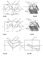
- la figure 6A représente une vue détaillée d'une ailette de désionisation d'un dispositif électrique de coupure selon un seconde mode de réalisation préférentiel ;
- la figure 6B représente une vue détaillée d'un empilement d'ailettes de désionisation selon la figure 6A ;
- les figures 7A, 7B représentent respectivement une vue détaillée d'une ailette et d'un empilement d'ailettes de désionisation d'un dispositif électrique de coupure selon une variante du second mode de réalisation préférentiel de l'invention ;
- les figures 9A à 10B représentent des variantes de réalisation d'ailettes de désioniation de la chambre d'extinction d'arc.
- la figure 11 représente une variante de réalisation d'un dispositif électrique de coupure selon la figure 1.
- FIG. 1 represents a side view of an electrical cut-off device according to a first preferred embodiment of the invention;
- FIG. 2 represents a sectional view along a plane II of an electrical cut-off device according to FIG. 1;
- FIG. 3 represents a sectional view along a plane JJ of an electric cut-off device according to FIG. 2;
- FIG. 4A represents a detailed view of a deionization fin of an electric breaking device according to FIG. 1;
- FIG. 4B represents a detailed view of a stack of deionization vanes according to FIG. 4A;
- FIGS. 5A and 5B respectively represent a detailed view of a fin and a stack of deionization vanes of an electric switching device according to a variant of the first preferred embodiment of the invention;
- FIG. 6A represents a detailed view of a deionization fin of an electric breaking device according to a second preferred embodiment;
- FIG. 6B shows a detailed view of a stack of deionization fins according to FIG. 6A;
- FIGS. 7A and 7B respectively represent a detailed view of a fin and a stack of deionization vanes of an electric switching device according to a variant of the second preferred embodiment of the invention;
- FIGS. 9A to 10B show alternative embodiments of fins for deionizing the arc extinction chamber.
- FIG. 11 represents an alternative embodiment of an electric switching device according to FIG. 1.
Selon un premier mode de réalisation préférentiel présenté sur les figures 1, 2 et 3, le dispositif électrique de coupure 30 comprend un boîtier 31 en matériau plastique moulé dans lequel sont disposés au moins un contact fixe 32 associé à au moins un contact mobile 33. Un ou plusieurs dispositifs de détection de défauts notamment de court-circuit, agissent sur un mécanisme d'actionnement 34 commandant l'ouverture du contact mobile 33.According to a first preferred embodiment shown in FIGS. 1, 2 and 3, the electrical cut-off
Le boîtier 31, de part sa forme, définit un plan géométrique longitudinal de référence xz.The
Dans ce mode de réalisation présenté, le dispositif électrique de coupure comprend deux contacts fixes 32 en U reliés respectivement à une borne électrique de raccordement. Le contact mobile 33, pouvant se déplacer en translation sous l'action du dispositif d'actionnement 34, permet de relier électriquement les deux contacts fixes 32. Le contact mobile 33 présente deux zones de contact 36 pouvant chacune respectivement collaborer avec un contact fixe 32. On définit ainsi deux volumes d'ouverture 35 correspondant à l'espace dans lequel sont disposés un contact fixe 32 et une zone de contact 36 associée au contact mobile 33.In this embodiment shown, the electrical cut-off device comprises two U-shaped fixed
En outre, chaque volume d'ouverture 35 est associé à une chambre d'extinction d'arc 10. La chambre d'extinction d'arc 10 s'ouvrant sur le volume d'ouverture 35, est délimitée par deux parois latérales 11 parallèles et placées de part et d'autre du plan géométrique longitudinal de référence xz, une paroi postérieure 6 éloignée du volume d'ouverture 35, une paroi inférieure 7 et une paroi supérieure 8.In addition, each opening
La chambre d'extinction d'arc 10 comprend un empilement d'au moins deux ailettes de désionisation 1 planes et perpendiculaires au plan géométrique longitudinal de référence xz. Lesdites ailettes sont de forme sensiblement rectangulaire et comportent un axe longitudinal 12 ainsi qu'un axe médian 13. Lesdites ailettes comprennent deux parties principales : une première partie antérieure 13a faisant face au volume d'ouverture 35 et s'étendant de la face antérieure de la chambre d'extinction 10 à l'axe médian 13, et une seconde partie postérieure 13b s'étendant de l'axe médian 13 à la paroi postérieure 6.The
Chaque ailette 1 comporte une arête libre d'attaque 5 destinée à être exposée à l'arc. L'arête libre d'attaque 5 forme un évidement 9 débouchant et s'étendant selon l'axe longitudinal 12, de la face antérieure de la chambre d'extinction 10 vers la paroi postérieure 6. Cet évidement 9 délimite deux branches latérales 1a, 1b.Each
L'évidement 9 d'au moins deux ailettes 1 est de forme asymétrique et comporte deux portions. Il comporte une première portion antérieure évasée 9a faisant face aux contacts 32, 33 placés dans le volume d'ouverture 35 et une seconde portion longitudinale postérieure plus étroite 9b.The
Selon un mode préférentiel de réalisation de l'invention, tel que représenté sur les figures 6A, 7A, l'arête d'attaque 5 parcourant la surface plane desdites au moins deux ailettes, est au moins deux fois en contact aux points a, b avec l'axe longitudinal 12 des ailettes. Dans un autre mode de réalisation préférentiel de l'invention, comme représenté sur les figures 4A et 5A, l'arête d'attaque 5 coupe trois fois aux points a, b, c l'axe longitudinal 12 desdites au moins deux ailettes.According to a preferred embodiment of the invention, as shown in FIGS. 6A, 7A, the
Selon ces modes préférentiels de réalisation de l'invention, l'évidement 9 est réalisé de manière à ce que lorsque deux ailettes sont empilées en alternance, il existe, selon l'axe z, au moins deux zones d'alignement a et b entre une branche latérale 1 a d'une première ailette 1 et au moins une branche latérale 1a d'une seconde ailette 1 placée dans une position alternée. Une ailette est dans une position alternée par rapport à une autre quand elle a subi une rotation de 180° autour de son axe longitudinal 12. De préférence, la première zone d'alignement a se situe dans la partie antérieure 13a de l'ailette 1.According to these preferred embodiments of the invention, the
Lorsque l'arête d'attaque 5 coupe trois fois l'axe longitudinal 12, il existe trois zones d'alignement a, b et c entre une branche latérale 1a d'une première ailette 1 et au moins une branche latérale 1a d'une seconde ailette 1 placée dans une position alternée. Il existe alors une zone de recouvrement 50 des branches latérales 1a. Chaque ailette comporte une zone de recouvrement 50 délimitée par l'intersection, aux points a et b, entre l'axe longitudinal 12 et l'arête d'attaque 5 de la première branche latérale 1a.When the
Selon ces deux modes préférentiels de réalisation de l'invention, les deux branches latérales 1a, 1b sont sensiblement placées de part et d'autre dudit axe longitudinal 12 et la première portion antérieure évasée 9a est coupée par l'axe longitudinal 12.According to these two preferred embodiments of the invention, the two
Dans les exemples de réalisation tel que représentés sur les figures 1 à 11, toutes les ailettes placées dans la chambre d'extinction d'arc 10 comportent le même évidement 9. L'empilement de l'ensemble des ailettes 1 de la chambre d'extinction d'arc 10 est réalisé de manière à ce qu'au moins deux des ailettes soient empilées en alternance afin que les formes de leur évidement 9 ne coïncident pas.In the exemplary embodiments as represented in FIGS. 1 to 11, all the fins placed in the
Avantageusement, toutes les ailettes 1 sont empilées en alternance, de manière à ce que chaque ailette 1 soit positionnée à coté d'une autre ailette ayant subi une rotation de 180° par rapport à son axe longitudinal 12.Advantageously, all the
Du fait de la forme asymétrique des évidements 9 des ailettes 1 et du fait de l'empilement en alternance desdites ailettes, est formée une cheminée 15 dont le conduit apparaît comme sensiblement fermé dans un plan xy perpendiculaire à l'axe longitudinal 16 de ladite cheminée 15.Due to the asymmetrical shape of the
Dans l'exemple de réalisation, la cheminée 15 s'étend sur toute la hauteur de la chambre, de la paroi inférieure 8 à la paroi supérieure 7.In the exemplary embodiment, the
En fonction de la forme des évidements 9 des ailettes 1, l'axe 16 de la cheminée 15 sera plus ou moins proche de la paroi postérieure 6 de la chambre d'extinction d'arc 10. La cheminée 15 est de préférence positionnée niveau de l'axe médian 13 de l'ailette 1 ou au-delà dudit axe vers la paroi postérieure 6.Depending on the shape of the
Les ailettes sont réalisées en matériau conducteur à base d'acier. Les ailettes de désionisation 1 empilées les unes sur les autres sont séparées les unes des autres par un espace d'échange 2. L'épaisseur de chaque espace d'échange 2, légèrement supérieure à l'épaisseur des ailettes.The fins are made of conductive material based on steel. The
Les gaz ou les vapeurs métalliques présents dans la chambre d'extinction d'arc 10 peuvent être évacués de manière traditionnelle au moyen d'au moins un canal d'évacuation relié à un ou plusieurs espace d'échange 2 via des trous d'évacuation. Les gaz peuvent être expulsés à l'extérieur du dispositif électrique de coupure au risque de provoquer des nuisances dans les locaux où sont placés les dispositifs de coupure.The gases or metal vapors present in the
Dans un mode de réalisation particulier de l'invention, des moyens de recyclage de gaz sont alors utilisés. Au moins un espace d'échange 2 est relié à au moins un conduit d'évacuation 3 via au moins un trou d'évacuation 4. Ledit au moins un conduit d'évacuation 3 est destiné d'une part à l'évacuation des gaz de la chambre d'extinction 10 et d'autre part à l'injection desdits gaz, via une ouverture 18, au niveau des contacts 32, 33 du volume d'ouverture 35. En outre, Ledit au moins conduit d'évacuation 3, s'étend d'au moins un trou d'évacuation 4 vers l'ouverture 18, le long d'au moins une paroi latérale 11. Ladite ouverture 18 est placée en vis à vis des contacts électriques 32, 33 du volume d'ouverture 35In a particular embodiment of the invention, gas recycling means are then used. At least one
Les gaz empruntent alors un conduit d'écoulement composé d'au moins un trou d'évacuation 4, d'au moins un conduit d'évacuation 3 et d'au moins une ouverture 18. Lesdits conduits d'évacuation 3 comportent, sur toute leur longueur et suivant l'axe x, une section A constante ou croissante. En outre, lesdits conduits d'évacuation 3 comportent aussi de préférence une section constante selon les axes y et z. Autrement dit, de l'entrée à la sortie des gaz des conduits d'évacuation 3, la section desdits conduits est sensiblement constante. Avantageusement la section desdits conduits peut être croissante. L'ouverture 18 est au moins égale à la plus grande section A dudit conduit.The gases then take a flow duct composed of at least one
De manière générale, la section d'un conduit d'écoulement emprunté par les gaz doit au moins rester constante ou augmenter. Cette particularité géométrique favorise l'écoulement des gaz provenant des espaces d'échange 2 et limite ainsi la création des bouchons de pression pouvant se former le long du conduit d'écoulement. Une diminution de la section du conduit d'écoulement, particulièrement au niveau du conduit d'évacuation 3 ou de l'ouverture 18, pourrait provoquer la naissance de bouchons de pression. Ces bouchons de pression pourraient engendrer un freinage dans la progression des gaz ainsi que dans la progression de l'arc électrique.In general, the section of a flow path taken by the gases must at least remain constant or increase. This geometrical feature promotes the flow of gases from the
Avantageusement, dans le mode de réalisation préférentiel de l'invention présenté sur les figures 1 à 3, chaque espace d'échange 2 est relié à au moins un conduit d'évacuation 3 via au moins un trou 4 d'évacuation. La forme et la dimension des trous d'évacuation 4 sont telles que l'écoulement gazeux n'entraîne pas le passage de l'arc par ces trous. Afin d'éviter des court-circuit entre les ailettes 1, via l'art électrique, les trous d'évacuation sont réalisés de manière indépendante et ne communiquent pas entre eux.Advantageously, in the preferred embodiment of the invention shown in FIGS. 1 to 3, each
De préférence, au moins deux conduits d'évacuation 3 sont présents de manière à ce qu'au moins un conduit 3 s'étende le long de chaque paroi latérale 11 de la chambre d'extinction d'arc 10. Dans l'exemple de réalisation présenté sur les figures 1 et 2, chaque conduit d'évacuation placé à coté d'une paroi latérale 11, s'étend des trous d'évacuation 4 vers une ouverture 18, de la paroi inférieure 8 à la paroi supérieure 7 et le long de la paroi latérale 11.Preferably, at least two
Dans un mode de réalisation préférentiel selon l'invention tel que représenté sur les figures 1 à 3, deux conduits d'évacuation 3 sont utilisés. Un conduit d'évacuation 3 est placé à coté de chacune des parois latérales 11 de la chambre d'extinction d'arc 10. Chaque espace d'échange 2 comporte au moins un trou d'évacuation 4 relié à un conduit d'évacuation 3. Les trous d'évacuation 4, placés dans les parois latérales 11, sont positionnés dans une zone comprise entre la paroi postérieure 6 et l'axe médian 13 des ailettes 1. En outre, les conduits sont de forme sensiblement parallélépipédique.In a preferred embodiment according to the invention as shown in Figures 1 to 3, two
L'appareillage fonctionne de la manière suivante. Lors de l'apparition d'un court circuit, le champ électromagnétique induit par le courant circulant dans les conducteurs et notamment dans le contact fixe 32, engendre dans le contact mobile 33 des forces électrodynamiques qui repoussent le contact mobile en position de séparation, ce mouvement étant par la suite confirmé par l'ouverture du mécanisme d'actionnement via le mécanisme 34. Dès la séparation des contacts 32, 33, un arc électrique naît entre lesdits contacts. Cet arc est poussé dans la chambre d'extinction d'arc 10 par les forces électrodynamiques. Lors de son déplacement vers la cheminée 15 et la paroi postérieure 6, l'arc reste à mi-distance entre les parois latérales 11, car il tend à emprunter les évidements 9 ouverts entre les ailettes.The apparatus operates in the following manner. During the appearance of a short circuit, the electromagnetic field induced by the current flowing in the conductors and in particular in the fixed
Les ailettes 1 offrent à l'arc une surface d'échange thermique durant toute la coupure, notamment dans leur partie à proximité des arêtes 5. Au cours de sa progression dans la chambre d'extinction d'arc 10 ou lorsqu'il est installé dans la cheminée 15, l'arc tend à se dilater pour envahir tout l'espace disponible. Les ailettes 1 contiennent cette dilatation en interagissant avec la périphérie de l'arc. Lorsque l'arc se situe dans la cheminée 15, l'échange thermique est réparti de façon uniforme autour de l'arc et permet ainsi d'optimiser son refroidissement et d'accélérer son extinction. La tension d'arc augmente au fur et à mesure que l'arc se refroidit ce qui permet finalement l'extinction de l'arc lors du passage du courant électrique par zéro.The
Les évidements 9 favorisent la migration de l'arc vers le fond de la chambre d'extinction d'arc 10, et la cheminée 15 stabilise l'arc dans cette région. Cette cheminée 15, éloignée du volume d'ouverture permet à l'arc de se stabiliser et de ne pas re-claquer de façon répétitive entre les contacts. C'est donc la conjonction de la forme de l'évidement et de la position respective des ailettes les unes par rapport aux autres qui permet d'éloigner rapidement et durablement l'arc des contacts.The
Par ailleurs, via les conduits d'évacuation 3, une convection gazeuse s'établit de sorte que la progression de l'arc vers la paroi postérieure 6 n'est pas entravée par une augmentation de pression. Le pied de l'arc migre rapidement du contact fixe 32 jusqu'à la cheminée 15, avant que le contact mobile 33 ait atteint sa position finale de séparation.Furthermore, via the
En pratique, les gaz émis à la périphérie de l'arc et présents dans les espaces d'échange 2 sont injectés dans le volume d'ouverture 35 via les conduits d'écoulement composés des trous d'évacuation 4, des conduits d'évacuation 3 et des ouvertures 18. La répartition homogène et régulière des gaz évacués par les conduits d'écoulement réduit le risque de bouchons de pression responsables du ralentissement de la progression des gaz et de la progression de l'arc. En effet, une augmentation locale de pression ou la présence de gaz froid, en avant de l'arc, peut entraîner un ralentissement dans son déplacement.In practice, the gases emitted at the periphery of the arc and present in the
La circulation des gaz dans les conduits d'écoulement en direction des contacts électriques 32, 33 du volume d'ouverture 35 permet une décompression desdits gaz compris ainsi qu'un refroidissement plus rapide de ces derniers.The flow of gases in the flow conduits towards the
L'injection des gaz refroidis au niveau des contacts 32, 33 présents dans le volume d'ouverture 35 permet d'augmenter la rigidité diélectrique dans cet espace et d'éviter ainsi des re-claquages intempestifs de l'arc électrique. De plus cette injection au niveau des contacts permet de soumettre le plasma présent dans le volume d'ouverture 35 et la chambre d'extinction d'arc 10 à un flux arrière de gaz froids et faiblement ionisés. Ceci provoque un refroidissement de la zone arrière de l'arc mais aussi l'envoi des gaz chauds en avant de l'arc. Du fait de son refroidissement par l'arrière, l'arc tendant à se développer en présence de gaz chauds ionisés associés à des vapeurs métalliques, se déplace vers là face postérieure 6 de la chambre d'extinction 10 et s'éloigne ainsi de la zone d'ouverture des contacts.The injection of the cooled gases at the
Selon une première série de variantes de réalisation telles que représentées sur les figures 6A et 7A, l'arête d'attaque 5 parcourant la surface plane des ailettes 1 et formant l'évidement 9 de forme asymétrique, coupe cinq fois aux points a, b, c, d, e l'axe longitudinal 12 desdites ailettes. Du fait de la forme asymétrique des évidements 9 de chaque ailette 1 et du fait de l'empilement en alternance desdites ailettes, sont formées deux cheminées 15 dont les conduits 16 apparaissent respectivement comme sensiblement fermés dans un plan perpendiculaire xy à l'axe longitudinal 16 desdites cheminées 15.According to a first series of alternative embodiments as shown in FIGS. 6A and 7A, the
Selon une seconde série de variantes de réalisation telles que représentées sur les figures 10a et 10b, l'arête d'attaque 5 parcourant la surface plane de l'ailette et formant l'évidement 9 de forme asymétrique coupe deux fois l'axe longitudinal 12 de ladite ailette. En outre, la première portion longitudinale évasée 9a est positionnée au-delà de l'axe longitudinal 12 des ailettes 1.According to a second series of alternative embodiments as shown in FIGS. 10a and 10b, the
Dans une autre variante de réalisation tel que représentée sur la figure 11, les espaces d'échange 2 comportent au moins un trou d'évacuation 4 placé dans la paroi postérieure 6 et relié à un conduit d'évacuation 3. Selon cet exemple de réalisation, chaque espace d'échange 2 comporte deux trous d'évacuation 4 ; chacun des trous est relié respectivement à un conduit d'évacuation 3.In another alternative embodiment as shown in FIG. 11, the
Dans une autre variante de réalisation, chaque trou 4 est relié de manière autonome à une ouverture 18 via son propre conduit d'évacuation 3. En effet, chaque conduit d'évacuation 3 reste indépendant des autres conduits d'évacuation.In another variant embodiment, each
Claims (15)
Applications Claiming Priority (1)
| Application Number | Priority Date | Filing Date | Title |
|---|---|---|---|
| FR0412972A FR2879019B1 (en) | 2004-12-06 | 2004-12-06 | ELECTRICAL CUTTING DEVICE WITH ARC EXTINGUISHING CHAMBER WITH DESIONIZATION FINS |
Publications (2)
| Publication Number | Publication Date |
|---|---|
| EP1667180A1 true EP1667180A1 (en) | 2006-06-07 |
| EP1667180B1 EP1667180B1 (en) | 2008-03-05 |
Family
ID=34951319
Family Applications (1)
| Application Number | Title | Priority Date | Filing Date |
|---|---|---|---|
| EP05354038A Not-in-force EP1667180B1 (en) | 2004-12-06 | 2005-10-20 | Electrical contactor and electric arc extinguishing chamber with deionisation blades |
Country Status (6)
| Country | Link |
|---|---|
| EP (1) | EP1667180B1 (en) |
| CN (1) | CN100541691C (en) |
| AT (1) | ATE388476T1 (en) |
| DE (1) | DE602005005142T2 (en) |
| ES (1) | ES2300964T3 (en) |
| FR (1) | FR2879019B1 (en) |
Cited By (3)
| Publication number | Priority date | Publication date | Assignee | Title |
|---|---|---|---|---|
| EP2109130A1 (en) * | 2008-04-09 | 2009-10-14 | Abb Ag | Arc welding anti-surge sheet metal assembly for an electrical switch |
| WO2014135641A3 (en) * | 2013-03-06 | 2016-01-14 | Eaton Electrical Ip Gmbh & Co. Kg | Plate stack for a cooling device in installation devices |
| US9622374B2 (en) | 2014-08-08 | 2017-04-11 | General Electric Company | Electrical equipment and a method of manufacturing |
Families Citing this family (3)
| Publication number | Priority date | Publication date | Assignee | Title |
|---|---|---|---|---|
| DE102012104992A1 (en) * | 2012-06-11 | 2013-12-12 | Eaton Industries Gmbh | switchgear |
| DE102016115223B4 (en) * | 2015-11-10 | 2022-02-17 | Dehn Se + Co Kg | Horn spark gap with deion chamber in non-extinguishing design |
| GB2606543A (en) * | 2021-05-12 | 2022-11-16 | Eaton Intelligent Power Ltd | Switchgear |
Citations (3)
| Publication number | Priority date | Publication date | Assignee | Title |
|---|---|---|---|---|
| FR1400079A (en) * | 1963-07-01 | 1965-05-21 | Thomson Houston Comp Francaise | Improvements to circuit breakers |
| US4612426A (en) * | 1985-08-23 | 1986-09-16 | Westinghouse Electric Corp. | Arc chute assembly for circuit breaker |
| FR2839195A1 (en) * | 2002-04-29 | 2003-10-31 | Schneider Electric Ind Sa | ELECTRICAL SWITCHING APPARATUS COMPRISING AN ARC EXTINGUISHING CHAMBER PROVIDED WITH DEIONIZING FINS |
-
2004
- 2004-12-06 FR FR0412972A patent/FR2879019B1/en not_active Expired - Fee Related
-
2005
- 2005-10-20 AT AT05354038T patent/ATE388476T1/en not_active IP Right Cessation
- 2005-10-20 ES ES05354038T patent/ES2300964T3/en active Active
- 2005-10-20 EP EP05354038A patent/EP1667180B1/en not_active Not-in-force
- 2005-10-20 DE DE602005005142T patent/DE602005005142T2/en active Active
- 2005-12-06 CN CNB2005101297514A patent/CN100541691C/en not_active Expired - Fee Related
Patent Citations (3)
| Publication number | Priority date | Publication date | Assignee | Title |
|---|---|---|---|---|
| FR1400079A (en) * | 1963-07-01 | 1965-05-21 | Thomson Houston Comp Francaise | Improvements to circuit breakers |
| US4612426A (en) * | 1985-08-23 | 1986-09-16 | Westinghouse Electric Corp. | Arc chute assembly for circuit breaker |
| FR2839195A1 (en) * | 2002-04-29 | 2003-10-31 | Schneider Electric Ind Sa | ELECTRICAL SWITCHING APPARATUS COMPRISING AN ARC EXTINGUISHING CHAMBER PROVIDED WITH DEIONIZING FINS |
Cited By (3)
| Publication number | Priority date | Publication date | Assignee | Title |
|---|---|---|---|---|
| EP2109130A1 (en) * | 2008-04-09 | 2009-10-14 | Abb Ag | Arc welding anti-surge sheet metal assembly for an electrical switch |
| WO2014135641A3 (en) * | 2013-03-06 | 2016-01-14 | Eaton Electrical Ip Gmbh & Co. Kg | Plate stack for a cooling device in installation devices |
| US9622374B2 (en) | 2014-08-08 | 2017-04-11 | General Electric Company | Electrical equipment and a method of manufacturing |
Also Published As
| Publication number | Publication date |
|---|---|
| CN1787138A (en) | 2006-06-14 |
| FR2879019A1 (en) | 2006-06-09 |
| CN100541691C (en) | 2009-09-16 |
| ES2300964T3 (en) | 2008-06-16 |
| FR2879019B1 (en) | 2008-04-04 |
| DE602005005142D1 (en) | 2008-04-17 |
| DE602005005142T2 (en) | 2009-03-19 |
| EP1667180B1 (en) | 2008-03-05 |
| ATE388476T1 (en) | 2008-03-15 |
Similar Documents
| Publication | Publication Date | Title |
|---|---|---|
| EP1667179B1 (en) | Electrical switchgear with recycling of cut-off gases | |
| EP2061051B1 (en) | Arc chamber and circuit breaker equipped with such an arc chamber | |
| EP1667180B1 (en) | Electrical contactor and electric arc extinguishing chamber with deionisation blades | |
| EP1359596B1 (en) | Electrical switching device having an arc extinguishing chamber with deionization plates | |
| EP2478539A2 (en) | Interrupter device having at least one single-pole phase unit comprising a contact bridge and circuit breaker comprising such a device | |
| FR3012662A1 (en) | BIDIRECTIONAL CONTINUOUS CURRENT ELECTRICAL SWITCHING DEVICE HAVING PERMANENT SMALL MAGNETS ON FERROMAGNETIC LATERAL ELEMENTS AND ARM CUTTING PLATE ASSEMBLY | |
| EP1115132B1 (en) | Pole for electrical circuit breaker with arc extinguishing chamber provided with dielectric shields | |
| EP2478544B1 (en) | Single-pole cutoff unit comprising a rotary contact bridge, cutoff device comprising such a unit, and circuit breaker comprising such a device | |
| EP2804189B1 (en) | Arc extinguising chamber for an electric protection apparatus and electric protection apparatus comprising same | |
| EP2894647B1 (en) | Unipolar breaking unit and switchgear comprising such a unit | |
| EP2936529B1 (en) | Unitary cut-off block and cut-off device, in particular contact switch comprising at least one such block | |
| EP4341973A1 (en) | Electrical protection apparatuses and systems having an integrated cut-off module | |
| FR2999790B1 (en) | UNIPOLAR CUT-OFF BLOCK AND CUTTING DEVICE COMPRISING SUCH A BLOCK | |
| EP3035363B1 (en) | Arc extinguishing chamber for electrical circuit breaker and circuit breaker comprising such a chamber | |
| FR3038124A1 (en) | ARC EXTINGUISHING DEVICE IN AN ELECTRICAL PROTECTION APPARATUS AND ELECTRICAL PROTECTION APPARATUS COMPRISING SUCH A DEVICE | |
| FR2981789A1 (en) | Electrical cut-off device e.g. circuit breaker, for cutting direct current in photovoltaic electricity generation station, has actuating mechanism with reversal unit to move mobile contact bridge between contact and separating positions | |
| FR2986659A1 (en) | Unipolar cut off block i.e. ampoule for use in tripolar circuit breaker, has axle fixed at sidewalls of discharge channel to divide rotative valve into non-symmetrical surfaces that are moved to release position to release bypass sections | |
| EP0713232B1 (en) | Arc chamber for an electrical circuit breaker | |
| FR2589625A1 (en) | Kinematic chain for transmission beween the control mechanism and the poles of an electric circuit breaker | |
| FR2950473A1 (en) | Unipolar cutoff unit useful in cutoff device for circuit-breaker, comprises rotating contact bridge, pair of fixed contacts connected with bridge, rotating rod having transverse opening, sealing shields, and arc extinction chambers | |
| FR2950474A1 (en) | Electrical interrupter device for e.g. tripolar circuit breaker, has chambers connected to channels that discharge onto upstream surface of case, where surface is positioned opposite to downstream surface placed in contact with trigger | |
| FR3016472A1 (en) | ELECTRIC CONTACT DEVICE AND LOW VOLTAGE UNIPOLAR CUT-OFF BLOCK INCORPORATING AN ELECTRICAL CONTACT DEVICE | |
| FR2950471A1 (en) | Unipolar cutoff unit useful in cutoff device for circuit-breaker, comprises rotating contact bridge, pair of fixed contacts connected with bridge, rotating rod having transverse opening, sealing shields, and arc extinction chambers | |
| FR2972074A1 (en) | Cassette for extinction of electric arc in unipolar bulb in circuit breaker of switching device, has casing whose front wall is bordered by flaps extending in direction perpendicular to front wall to mask sides of housing | |
| FR3059460A1 (en) | CHAMBER FOR RELAXATION OF A DIFFERENTIAL CIRCUIT BREAKER AND CIRCUIT BREAKER THUS EQUIPPED |
Legal Events
| Date | Code | Title | Description |
|---|---|---|---|
| PUAI | Public reference made under article 153(3) epc to a published international application that has entered the european phase |
Free format text: ORIGINAL CODE: 0009012 |
|
| AK | Designated contracting states |
Kind code of ref document: A1 Designated state(s): AT BE BG CH CY CZ DE DK EE ES FI FR GB GR HU IE IS IT LI LT LU LV MC NL PL PT RO SE SI SK TR |
|
| AX | Request for extension of the european patent |
Extension state: AL BA HR MK YU |
|
| 17P | Request for examination filed |
Effective date: 20061110 |
|
| 17Q | First examination report despatched |
Effective date: 20061208 |
|
| AKX | Designation fees paid |
Designated state(s): AT BE BG CH CY CZ DE DK EE ES FI FR GB GR HU IE IS IT LI LT LU LV MC NL PL PT RO SE SI SK TR |
|
| GRAP | Despatch of communication of intention to grant a patent |
Free format text: ORIGINAL CODE: EPIDOSNIGR1 |
|
| GRAS | Grant fee paid |
Free format text: ORIGINAL CODE: EPIDOSNIGR3 |
|
| GRAA | (expected) grant |
Free format text: ORIGINAL CODE: 0009210 |
|
| AK | Designated contracting states |
Kind code of ref document: B1 Designated state(s): AT BE BG CH CY CZ DE DK EE ES FI FR GB GR HU IE IS IT LI LT LU LV MC NL PL PT RO SE SI SK TR |
|
| REG | Reference to a national code |
Ref country code: GB Ref legal event code: FG4D Free format text: NOT ENGLISH |
|
| REG | Reference to a national code |
Ref country code: CH Ref legal event code: EP |
|
| REG | Reference to a national code |
Ref country code: IE Ref legal event code: FG4D Free format text: LANGUAGE OF EP DOCUMENT: FRENCH |
|
| REF | Corresponds to: |
Ref document number: 602005005142 Country of ref document: DE Date of ref document: 20080417 Kind code of ref document: P |
|
| REG | Reference to a national code |
Ref country code: ES Ref legal event code: FG2A Ref document number: 2300964 Country of ref document: ES Kind code of ref document: T3 |
|
| PG25 | Lapsed in a contracting state [announced via postgrant information from national office to epo] |
Ref country code: FI Free format text: LAPSE BECAUSE OF FAILURE TO SUBMIT A TRANSLATION OF THE DESCRIPTION OR TO PAY THE FEE WITHIN THE PRESCRIBED TIME-LIMIT Effective date: 20080305 |
|
| PG25 | Lapsed in a contracting state [announced via postgrant information from national office to epo] |
Ref country code: AT Free format text: LAPSE BECAUSE OF FAILURE TO SUBMIT A TRANSLATION OF THE DESCRIPTION OR TO PAY THE FEE WITHIN THE PRESCRIBED TIME-LIMIT Effective date: 20080305 |
|
| NLV1 | Nl: lapsed or annulled due to failure to fulfill the requirements of art. 29p and 29m of the patents act | ||
| PG25 | Lapsed in a contracting state [announced via postgrant information from national office to epo] |
Ref country code: LV Free format text: LAPSE BECAUSE OF FAILURE TO SUBMIT A TRANSLATION OF THE DESCRIPTION OR TO PAY THE FEE WITHIN THE PRESCRIBED TIME-LIMIT Effective date: 20080305 Ref country code: SI Free format text: LAPSE BECAUSE OF FAILURE TO SUBMIT A TRANSLATION OF THE DESCRIPTION OR TO PAY THE FEE WITHIN THE PRESCRIBED TIME-LIMIT Effective date: 20080305 Ref country code: PL Free format text: LAPSE BECAUSE OF FAILURE TO SUBMIT A TRANSLATION OF THE DESCRIPTION OR TO PAY THE FEE WITHIN THE PRESCRIBED TIME-LIMIT Effective date: 20080305 |
|
| REG | Reference to a national code |
Ref country code: IE Ref legal event code: FD4D |
|
| PG25 | Lapsed in a contracting state [announced via postgrant information from national office to epo] |
Ref country code: PT Free format text: LAPSE BECAUSE OF FAILURE TO SUBMIT A TRANSLATION OF THE DESCRIPTION OR TO PAY THE FEE WITHIN THE PRESCRIBED TIME-LIMIT Effective date: 20080805 Ref country code: NL Free format text: LAPSE BECAUSE OF FAILURE TO SUBMIT A TRANSLATION OF THE DESCRIPTION OR TO PAY THE FEE WITHIN THE PRESCRIBED TIME-LIMIT Effective date: 20080305 Ref country code: SK Free format text: LAPSE BECAUSE OF FAILURE TO SUBMIT A TRANSLATION OF THE DESCRIPTION OR TO PAY THE FEE WITHIN THE PRESCRIBED TIME-LIMIT Effective date: 20080305 Ref country code: SE Free format text: LAPSE BECAUSE OF FAILURE TO SUBMIT A TRANSLATION OF THE DESCRIPTION OR TO PAY THE FEE WITHIN THE PRESCRIBED TIME-LIMIT Effective date: 20080605 Ref country code: CZ Free format text: LAPSE BECAUSE OF FAILURE TO SUBMIT A TRANSLATION OF THE DESCRIPTION OR TO PAY THE FEE WITHIN THE PRESCRIBED TIME-LIMIT Effective date: 20080305 |
|
| PG25 | Lapsed in a contracting state [announced via postgrant information from national office to epo] |
Ref country code: RO Free format text: LAPSE BECAUSE OF FAILURE TO SUBMIT A TRANSLATION OF THE DESCRIPTION OR TO PAY THE FEE WITHIN THE PRESCRIBED TIME-LIMIT Effective date: 20080305 |
|
| PG25 | Lapsed in a contracting state [announced via postgrant information from national office to epo] |
Ref country code: IS Free format text: LAPSE BECAUSE OF FAILURE TO SUBMIT A TRANSLATION OF THE DESCRIPTION OR TO PAY THE FEE WITHIN THE PRESCRIBED TIME-LIMIT Effective date: 20080705 |
|
| PLBE | No opposition filed within time limit |
Free format text: ORIGINAL CODE: 0009261 |
|
| STAA | Information on the status of an ep patent application or granted ep patent |
Free format text: STATUS: NO OPPOSITION FILED WITHIN TIME LIMIT |
|
| PG25 | Lapsed in a contracting state [announced via postgrant information from national office to epo] |
Ref country code: LT Free format text: LAPSE BECAUSE OF FAILURE TO SUBMIT A TRANSLATION OF THE DESCRIPTION OR TO PAY THE FEE WITHIN THE PRESCRIBED TIME-LIMIT Effective date: 20080305 Ref country code: DK Free format text: LAPSE BECAUSE OF FAILURE TO SUBMIT A TRANSLATION OF THE DESCRIPTION OR TO PAY THE FEE WITHIN THE PRESCRIBED TIME-LIMIT Effective date: 20080305 Ref country code: IE Free format text: LAPSE BECAUSE OF FAILURE TO SUBMIT A TRANSLATION OF THE DESCRIPTION OR TO PAY THE FEE WITHIN THE PRESCRIBED TIME-LIMIT Effective date: 20080305 |
|
| 26N | No opposition filed |
Effective date: 20081208 |
|
| BERE | Be: lapsed |
Owner name: SCHNEIDER ELECTRIC INDUSTRIES SAS Effective date: 20081031 |
|
| PG25 | Lapsed in a contracting state [announced via postgrant information from national office to epo] |
Ref country code: BG Free format text: LAPSE BECAUSE OF FAILURE TO SUBMIT A TRANSLATION OF THE DESCRIPTION OR TO PAY THE FEE WITHIN THE PRESCRIBED TIME-LIMIT Effective date: 20080605 Ref country code: EE Free format text: LAPSE BECAUSE OF FAILURE TO SUBMIT A TRANSLATION OF THE DESCRIPTION OR TO PAY THE FEE WITHIN THE PRESCRIBED TIME-LIMIT Effective date: 20080305 |
|
| PG25 | Lapsed in a contracting state [announced via postgrant information from national office to epo] |
Ref country code: MC Free format text: LAPSE BECAUSE OF NON-PAYMENT OF DUE FEES Effective date: 20081031 |
|
| PG25 | Lapsed in a contracting state [announced via postgrant information from national office to epo] |
Ref country code: CY Free format text: LAPSE BECAUSE OF FAILURE TO SUBMIT A TRANSLATION OF THE DESCRIPTION OR TO PAY THE FEE WITHIN THE PRESCRIBED TIME-LIMIT Effective date: 20080305 Ref country code: BE Free format text: LAPSE BECAUSE OF NON-PAYMENT OF DUE FEES Effective date: 20081031 |
|
| REG | Reference to a national code |
Ref country code: CH Ref legal event code: PL |
|
| PG25 | Lapsed in a contracting state [announced via postgrant information from national office to epo] |
Ref country code: LU Free format text: LAPSE BECAUSE OF NON-PAYMENT OF DUE FEES Effective date: 20081020 Ref country code: HU Free format text: LAPSE BECAUSE OF FAILURE TO SUBMIT A TRANSLATION OF THE DESCRIPTION OR TO PAY THE FEE WITHIN THE PRESCRIBED TIME-LIMIT Effective date: 20080906 |
|
| PG25 | Lapsed in a contracting state [announced via postgrant information from national office to epo] |
Ref country code: TR Free format text: LAPSE BECAUSE OF FAILURE TO SUBMIT A TRANSLATION OF THE DESCRIPTION OR TO PAY THE FEE WITHIN THE PRESCRIBED TIME-LIMIT Effective date: 20080305 |
|
| PG25 | Lapsed in a contracting state [announced via postgrant information from national office to epo] |
Ref country code: CH Free format text: LAPSE BECAUSE OF NON-PAYMENT OF DUE FEES Effective date: 20091031 Ref country code: GR Free format text: LAPSE BECAUSE OF FAILURE TO SUBMIT A TRANSLATION OF THE DESCRIPTION OR TO PAY THE FEE WITHIN THE PRESCRIBED TIME-LIMIT Effective date: 20080606 Ref country code: LI Free format text: LAPSE BECAUSE OF NON-PAYMENT OF DUE FEES Effective date: 20091031 |
|
| REG | Reference to a national code |
Ref country code: FR Ref legal event code: PLFP Year of fee payment: 12 |
|
| REG | Reference to a national code |
Ref country code: FR Ref legal event code: PLFP Year of fee payment: 13 |
|
| REG | Reference to a national code |
Ref country code: FR Ref legal event code: PLFP Year of fee payment: 14 |
|
| PGFP | Annual fee paid to national office [announced via postgrant information from national office to epo] |
Ref country code: DE Payment date: 20181024 Year of fee payment: 14 |
|
| PGFP | Annual fee paid to national office [announced via postgrant information from national office to epo] |
Ref country code: FR Payment date: 20181024 Year of fee payment: 14 Ref country code: GB Payment date: 20181017 Year of fee payment: 14 Ref country code: ES Payment date: 20181102 Year of fee payment: 14 Ref country code: IT Payment date: 20181018 Year of fee payment: 14 |
|
| REG | Reference to a national code |
Ref country code: DE Ref legal event code: R119 Ref document number: 602005005142 Country of ref document: DE |
|
| PG25 | Lapsed in a contracting state [announced via postgrant information from national office to epo] |
Ref country code: DE Free format text: LAPSE BECAUSE OF NON-PAYMENT OF DUE FEES Effective date: 20200501 |
|
| GBPC | Gb: european patent ceased through non-payment of renewal fee |
Effective date: 20191020 |
|
| PG25 | Lapsed in a contracting state [announced via postgrant information from national office to epo] |
Ref country code: GB Free format text: LAPSE BECAUSE OF NON-PAYMENT OF DUE FEES Effective date: 20191020 Ref country code: IT Free format text: LAPSE BECAUSE OF NON-PAYMENT OF DUE FEES Effective date: 20191020 Ref country code: FR Free format text: LAPSE BECAUSE OF NON-PAYMENT OF DUE FEES Effective date: 20191031 |
|
| REG | Reference to a national code |
Ref country code: ES Ref legal event code: FD2A Effective date: 20210302 |
|
| PG25 | Lapsed in a contracting state [announced via postgrant information from national office to epo] |
Ref country code: ES Free format text: LAPSE BECAUSE OF NON-PAYMENT OF DUE FEES Effective date: 20191021 |