EP1664538B1 - Mit einer schwimmersteuervorrichtung ausgestattete tauchpumpe - Google Patents
Mit einer schwimmersteuervorrichtung ausgestattete tauchpumpe Download PDFInfo
- Publication number
- EP1664538B1 EP1664538B1 EP04764386A EP04764386A EP1664538B1 EP 1664538 B1 EP1664538 B1 EP 1664538B1 EP 04764386 A EP04764386 A EP 04764386A EP 04764386 A EP04764386 A EP 04764386A EP 1664538 B1 EP1664538 B1 EP 1664538B1
- Authority
- EP
- European Patent Office
- Prior art keywords
- pump
- float
- structure according
- pump structure
- control device
- Prior art date
- Legal status (The legal status is an assumption and is not a legal conclusion. Google has not performed a legal analysis and makes no representation as to the accuracy of the status listed.)
- Expired - Lifetime
Links
- 238000007654 immersion Methods 0.000 title claims abstract description 13
- 230000001360 synchronised effect Effects 0.000 claims abstract description 11
- 239000000523 sample Substances 0.000 claims description 13
- 239000012530 fluid Substances 0.000 claims description 11
- 230000005355 Hall effect Effects 0.000 claims description 3
- 238000004891 communication Methods 0.000 claims description 3
- 238000000926 separation method Methods 0.000 claims description 2
- XLYOFNOQVPJJNP-UHFFFAOYSA-N water Substances O XLYOFNOQVPJJNP-UHFFFAOYSA-N 0.000 description 5
- 239000010865 sewage Substances 0.000 description 3
- 238000010276 construction Methods 0.000 description 1
- 230000007423 decrease Effects 0.000 description 1
- 238000006073 displacement reaction Methods 0.000 description 1
- 239000003344 environmental pollutant Substances 0.000 description 1
- 238000009434 installation Methods 0.000 description 1
- 238000009413 insulation Methods 0.000 description 1
- 238000004519 manufacturing process Methods 0.000 description 1
- 238000012544 monitoring process Methods 0.000 description 1
- 230000003287 optical effect Effects 0.000 description 1
- 231100000719 pollutant Toxicity 0.000 description 1
- 238000005086 pumping Methods 0.000 description 1
- 239000011347 resin Substances 0.000 description 1
- 229920005989 resin Polymers 0.000 description 1
- 230000035945 sensitivity Effects 0.000 description 1
- 239000002699 waste material Substances 0.000 description 1
Images



Classifications
-
- F—MECHANICAL ENGINEERING; LIGHTING; HEATING; WEAPONS; BLASTING
- F04—POSITIVE - DISPLACEMENT MACHINES FOR LIQUIDS; PUMPS FOR LIQUIDS OR ELASTIC FLUIDS
- F04D—NON-POSITIVE-DISPLACEMENT PUMPS
- F04D15/00—Control, e.g. regulation, of pumps, pumping installations or systems
- F04D15/02—Stopping of pumps, or operating valves, on occurrence of unwanted conditions
- F04D15/0209—Stopping of pumps, or operating valves, on occurrence of unwanted conditions responsive to a condition of the working fluid
- F04D15/0218—Stopping of pumps, or operating valves, on occurrence of unwanted conditions responsive to a condition of the working fluid the condition being a liquid level or a lack of liquid supply
Definitions
- the present invention relates to an immersion pump driven by a permanent-magnet synchronous electric motor and particularly, but not exclusively, suitable for a submersed installation in drain basins or tanks or in a sewage floodway.
- immersion pumps are used to rapidly pump down sewage collection tanks or however when fluids flowing in a recess are to be discharged, whose draining requires the fluid to exceed a given head.
- a typical application in the civil field is represented by pumping down sewage collection basins or tanks positioned in underground rooms located at a lower level than the corresponding sewerage network.
- a float control device comprising a level sensor of the fluid to be discharged is generally associated to an immersion pump; the sensor allows the pump to be turned on when the fluid level is kept above a predetermined threshold and the pump to be turned off when the fluid level reaches a minimum value.
- the German patent n° DE 3607466A describes a unit pump with a float level regulator housed in a guide located parallel to the body of the pump.
- the guide guides the float in its displacements.
- the float comprises at least one magnet (15), which acts at least on a Hall generator controlling the triggering of the regulator.
- a control device connects the Hall generator and switches provided for monitoring pump functions: switch-on and switch-off.
- Such pumps are advantageously realised with permanent-magnet synchronous motors which are cheap and very reliable and they have the only drawback of a difficult turn-on due to the need to overcome the initial load inertia before reaching a steady synchronism state.
- the float control device which is generally floating with respect to the pump body, is responsible for allowing the pump to be turned on or turned off.
- a first aim of the present invention is to provide an immersion pump with a float control device incorporated in the pump body.
- a further aim of the invention is to provide an immersion pump with a float control device having a simple construction and being reliable and low-cost.
- a pump structure as previously indicated and characterised in that the float of said control device is incorporated in an envelope, externally associated with the pump body, and a sensor element of said control device is housed in the pump body in correspondence with said float.
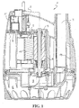
- a synchronous pump structure is globally and schematically indicated with 1, particularly an immersion pump installed in a submersed way in fluid collection basins or tanks.
- the pump 1 has a substantially-truncated-cone-shaped body 15 being equipped in the upper part with a lid 18 covering a top portion 12 of the pump body 15.
- the pump 1 is turned on by a synchronous electric motor 2 which can be both of the mechanical turn-on type and of the electronics-aided turn-on type.
- the electric motor 2 of the pump 1, shown in figure 1, comprises a stator 10 and a substantially cylindrical permanent-magnet central rotor 8.
- the motor 2 has an axis X-X substantially coinciding with the rotor 8 rotation axis.
- the stator 10 comprises asymmetrical pole pieces shown in figure 1.
- the operation of the pump 1 is adjusted by an electronic turn-on and turn-off device, schematically shown in figures 6 and 7 in the shape of components assembled on an electronic board 28 and interlocked with a float control device 3 realised according to the invention.
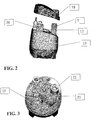
- the base 13 has a side portion 23 equipped with a grate 29 putting the internal part of the envelope 11 in fluid communication with the external environment. Internally, close to this side portion 23, a semi-cylinder-shaped filter element 14 is provided whose function will be explained hereafter.
- the filter 14 is kept in position by two opposite bulkheads 24, 30 partially projecting towards the internal part of the envelope 11.
- a float 16 is housed inside the envelope 11.
- a lid 20 is fitted on the base 13 defining therewith a chamber of the envelope 11 wherein the float 16 can freely move in the portion being not occupied by the filter.
- the lid 20 has a knob 22 which can be handled by a user in order to adjust, with a predetermined angle amplitude, for example between 90° and 180°, the float 16 position on the horizontal plane.
- the water inflow determining the float 16 movement is ensured by the grate-shaped wall 29 drawn in the side wall 23 of the base 13.
- the filter 14 is located within the grate-shaped wall 29 in order to prevent suspended bodies or other pollutants from contacting the float 16 and jeopardising the free movement thereof.
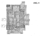
- An electronic board 28, suitable for housing the pump turn-on and turn-off electronic device, is advantageously housed within the pump body 15 in a position just underlying the float control device 3.
- the board 28 is equipped at one end with a Hall probe 27 housed on a board surface in a position facing the permanent magnet 19 of the float 16.
- the mobile position of the float 16 can provide a reciprocal separation and approach of the magnet 19 with the Hall probe 27, but also a misalignment of the probe 27 and the magnet 19, as it will be apparent in the following description.
- An insulating resin layer 25 separates the board 28 from the internal wall of the pump body 15, just between the Hall probe and the magnet 19.
- the upper wall of the pump body 15 insulates the Hall probe 27 and the magnet 19 so that all the live circuit parts have a double insulation with respect to the internal area of the envelope 11 containing water.
- the vertical axis of the float 16 coincides with the Hall probe 27axis.
- the pump turn-off thus occurs when two conditions simultaneously occur:
- control device 3 This situation is interpreted by the control device 3 as the pump being always submersed and thus always moving even with air in the impeller chamber.
- the so-equipped pump is more compact and it substantially incorporates a function being previously required by external components.
Landscapes
- Engineering & Computer Science (AREA)
- Mechanical Engineering (AREA)
- General Engineering & Computer Science (AREA)
- Structures Of Non-Positive Displacement Pumps (AREA)
- Control Of Non-Positive-Displacement Pumps (AREA)
- Special Spraying Apparatus (AREA)
- External Artificial Organs (AREA)
- Stabilization Of Oscillater, Synchronisation, Frequency Synthesizers (AREA)
Claims (11)
- Synchronpumpenaufbau, insbesondere Tauchpumpe (1), die mit einer Schwimmkörper-Steuervorrichtung (3) ausgestattet ist und einen Synchronelektromotor (2) mit einem Permanentmagnetrotor (8) umfasst, bei welchem Pumpenaufbau der Schwimmkörper (16) der Steuervorrichtung (3) in eine Kammer eines Hüllkörpers (11) eingebracht ist, der an den Korpus (15) der Pumpe (1) extern angeschlossen ist, dadurch gekennzeichnet, dass der Hüllkörper (11) eine Basis (13) umfasst, die drehbar am Korpus (15) angebracht ist, und ein Sensorelement (4) der Steuervorrichtung (3) in dem Korpus (15) in Entsprechung mit der Basis (13) aufgenommen ist, wobei sich der Schwimmkörper (16) frei innerhalb der Kammer bewegt und dabei eine hin- und hergehende Wegbewegung vom und Annäherung an das Sensorelement (4) entlang einer Achse bereitstellt, die mit einer vertikalen Achse des Sensorelements (4) entsprechend der Position der Basis (13) zusammenfällt oder zu dieser versetzt ist.
- Pumpenaufbau nach Anspruch 1, dadurch gekennzeichnet, dass das Sensorelement ein magnetisch arbeitender Pegelsensor (4) mit Hall-Effekt ist.
- Pumpenaufbau nach Anspruch 1, dadurch gekennzeichnet, dass der Schwimmkörper (16) an seinem unteren Teil mit einem Permanentmagneten (19) ausgestattet ist.
- Pumpenaufbau nach Anspruch 1, dadurch gekennzeichnet, dass der Hüllkörper (11) die Basis (13) umfasst, die ein zylindrischer, napfförmiger Abschnitt ist, und einen Deckel (20), der mit dem Basisabschnitt (13) die geschlossene Kammer bildet.
- Pumpenaufbau nach Anspruch 4, dadurch gekennzeichnet, dass der Deckel (20) einen Ansatz (22) umfasst, der von einem Benutzer betätigt werden kann, um die Position des Schwimmkörpers (16) in der Horizontalebene einzustellen.
- Pumpenaufbau nach Anspruch 2, dadurch gekennzeichnet, dass der Hall-Effekt-Sensor (4) einen Fühler (27) umfasst, der auf einer in dem Pumpenkorpus (15) untergebrachten elektronischen Leiterplatte in einer unter dem Schwimmkörper (16) liegenden Position angebracht ist.
- Pumpenaufbau nach Anspruch 4, dadurch gekennzeichnet, dass der Basisabschnitt (13) eine mit einem Gitter (29) ausgestattete Seitenwand (23) hat, um den inneren Teil des Hüllkörpers (11) in Fluidverbindung mit der Außenumgebung zu setzen.
- Pumpenaufbau nach Anspruch 7, dadurch gekennzeichnet, dass im Inneren nahe dem Seitenabschnitt (23) ein halbzylinderförmiges Filterelement (14) vorgesehen ist.
- Pumpenaufbau nach Anspruch 8, bei dem der Filter (14) durch zwei gegenüberliegende Abschlussplatten (24, 30) in Position gehalten wird, die teilweise zum inneren Teil des Hüllkörpers (11) hin vorspringen.
- Pumpenaufbau nach Anspruch 2, bei dem die Position des Schwimmkörpers (16) per Hand eingestellt werden kann, um so in Bezug auf das Sensorelement (4) versetzt zu sein.
- Pumpenaufbau nach einem oder mehreren vorhergehenden Ansprüchen, dadurch gekennzeichnet, dass der Hüllkörper (11) in einem oberen Teil (12) des Pumpenkorpus (15) sitzt.
Applications Claiming Priority (2)
| Application Number | Priority Date | Filing Date | Title |
|---|---|---|---|
| IT001662A ITMI20031662A1 (it) | 2003-08-22 | 2003-08-22 | Struttura di pompa sincrona, in particolare una pompa ad |
| PCT/EP2004/009405 WO2005019649A1 (en) | 2003-08-22 | 2004-08-23 | Immersion pump equipped with a float control device |
Publications (2)
| Publication Number | Publication Date |
|---|---|
| EP1664538A1 EP1664538A1 (de) | 2006-06-07 |
| EP1664538B1 true EP1664538B1 (de) | 2006-12-06 |
Family
ID=34204176
Family Applications (1)
| Application Number | Title | Priority Date | Filing Date |
|---|---|---|---|
| EP04764386A Expired - Lifetime EP1664538B1 (de) | 2003-08-22 | 2004-08-23 | Mit einer schwimmersteuervorrichtung ausgestattete tauchpumpe |
Country Status (7)
| Country | Link |
|---|---|
| US (1) | US7704050B2 (de) |
| EP (1) | EP1664538B1 (de) |
| AT (1) | ATE347652T1 (de) |
| DE (1) | DE602004003592T2 (de) |
| ES (1) | ES2280994T3 (de) |
| IT (1) | ITMI20031662A1 (de) |
| WO (1) | WO2005019649A1 (de) |
Families Citing this family (4)
| Publication number | Priority date | Publication date | Assignee | Title |
|---|---|---|---|---|
| US8696331B2 (en) * | 2008-05-06 | 2014-04-15 | Fmc Technologies, Inc. | Pump with magnetic bearings |
| WO2009137324A2 (en) * | 2008-05-06 | 2009-11-12 | Fmc Technologies, Inc. | Motor with high pressure rated can |
| US10193546B1 (en) * | 2015-01-23 | 2019-01-29 | S.J. Electro Systems, Inc. | Pump switching device |
| CN115788919A (zh) | 2021-09-09 | 2023-03-14 | 创科无线普通合伙 | 潜水泵 |
Family Cites Families (17)
| Publication number | Priority date | Publication date | Assignee | Title |
|---|---|---|---|---|
| US3316845A (en) * | 1965-07-28 | 1967-05-02 | Alfred F Schumann | Bilge pump |
| SE328149B (de) * | 1966-08-23 | 1970-09-07 | Svenska Precisionsverktyg Ab | |
| US3897172A (en) * | 1973-04-02 | 1975-07-29 | Wayne Home Equipment Co Inc | Motor control assembly for submersible sump pump |
| US4275995A (en) * | 1979-01-10 | 1981-06-30 | Taylor Thomas K | Bilge pump |
| US4345879A (en) * | 1979-12-06 | 1982-08-24 | Simer Pump Company | Hydraulic switch for a pump |
| DE3607466A1 (de) * | 1986-03-07 | 1987-09-24 | Blum Albert | Pumpenaggregat mit einer niveauschalteinrichtung |
| ES2026412A6 (es) * | 1990-11-15 | 1992-04-16 | Transpar Iberica Sa | Bomba para lavaparabrisas provista de dispositivo sensor de nivel. |
| US5297939A (en) * | 1993-02-01 | 1994-03-29 | Johnson Pumps Of America, Inc. | Automatic control for bilge & sump pump |
| US5324171A (en) * | 1993-05-14 | 1994-06-28 | Liberty Pumps | Pump assembly including a hermetically sealed switch capsule for housing a magnetically actuated switch |
| US5562423A (en) * | 1994-10-17 | 1996-10-08 | Johnson Pumps Of America, Inc. | Automatic float control switch for a bilge and sump pump |
| DE19507010A1 (de) * | 1995-02-28 | 1996-08-29 | Abs Pumps Ltd | Tauchmotorpumpe mit Schwimmerschalter |
| US5622477A (en) * | 1995-08-15 | 1997-04-22 | Johnson Pumps Of America, Inc. | Switch for bilge and sump/pump with automatic float control |
| US5833437A (en) * | 1996-07-02 | 1998-11-10 | Shurflo Pump Manufacturing Co. | Bilge pump |
| FR2767875B3 (fr) * | 1997-09-04 | 1999-08-13 | Askoll Holding Srl | Pompe centrifuge fonctionnant en immersion |
| DE19830416C1 (de) * | 1998-07-08 | 1999-12-09 | Hanning & Kahl Gmbh & Co | Pumpe mit schwimmbetätigter Abschaltautomatik |
| US6390780B1 (en) * | 1998-09-24 | 2002-05-21 | Rule Industries, Inc. | Pump and controller system and method |
| US6499961B1 (en) * | 2000-03-16 | 2002-12-31 | Tecumseh Products Company | Solid state liquid level sensor and pump controller |
-
2003
- 2003-08-22 IT IT001662A patent/ITMI20031662A1/it unknown
-
2004
- 2004-08-23 AT AT04764386T patent/ATE347652T1/de not_active IP Right Cessation
- 2004-08-23 EP EP04764386A patent/EP1664538B1/de not_active Expired - Lifetime
- 2004-08-23 ES ES04764386T patent/ES2280994T3/es not_active Expired - Lifetime
- 2004-08-23 DE DE602004003592T patent/DE602004003592T2/de not_active Expired - Lifetime
- 2004-08-23 WO PCT/EP2004/009405 patent/WO2005019649A1/en not_active Ceased
- 2004-08-23 US US10/568,040 patent/US7704050B2/en active Active
Also Published As
| Publication number | Publication date |
|---|---|
| WO2005019649A1 (en) | 2005-03-03 |
| DE602004003592D1 (de) | 2007-01-18 |
| US7704050B2 (en) | 2010-04-27 |
| ITMI20031662A1 (it) | 2005-02-23 |
| ATE347652T1 (de) | 2006-12-15 |
| US20070172359A1 (en) | 2007-07-26 |
| DE602004003592T2 (de) | 2007-10-11 |
| ES2280994T3 (es) | 2007-09-16 |
| EP1664538A1 (de) | 2006-06-07 |
Similar Documents
| Publication | Publication Date | Title |
|---|---|---|
| US5562422A (en) | Liquid level control assembly for pumps | |
| KR100306204B1 (ko) | 펌프장치및그작동법 | |
| JPH078877Y2 (ja) | 水中ポンプ用制御装置 | |
| CN102705265B (zh) | 空调机用排水泵 | |
| US5297939A (en) | Automatic control for bilge & sump pump | |
| US7704050B2 (en) | Immersion pump equipped with a float control device | |
| US4345879A (en) | Hydraulic switch for a pump | |
| US8535014B2 (en) | System and method for explosion-proof pump | |
| EP1819885B1 (de) | Pumpabwasser | |
| US7695251B2 (en) | Electronic control device for a synchronous pump | |
| JP2006070729A (ja) | 水中ポンプ | |
| US6474952B1 (en) | Sump pump motor switch assembly | |
| CA2213765A1 (en) | Submersible motor-driven pump with float switch | |
| KR100877236B1 (ko) | 에어컨용 배수펌프 | |
| JP5075390B2 (ja) | ポンプ | |
| EP1233188A1 (de) | Niveauabhängige Steuerung von Pumpen | |
| JP7019397B2 (ja) | ポンプ装置 | |
| EP1130267B1 (de) | Tauchpumpe mit integriertem Schwimmschalter | |
| CN222459757U (zh) | 一种水满报警的可拆卸水箱 | |
| JP2002122093A (ja) | 自動運転型水中ポンプ | |
| JP2006022668A (ja) | 水中ポンプおよび水中ポンプ装置 | |
| KR20190025092A (ko) | 응급구조 재난용 수중모터펌프 | |
| KR20010001465A (ko) | 침수감지 센서 | |
| JPS5923338Y2 (ja) | オ−トポンプ | |
| JP7030437B2 (ja) | ケーブル支持構造及びポンプ装置 |
Legal Events
| Date | Code | Title | Description |
|---|---|---|---|
| PUAI | Public reference made under article 153(3) epc to a published international application that has entered the european phase |
Free format text: ORIGINAL CODE: 0009012 |
|
| 17P | Request for examination filed |
Effective date: 20060315 |
|
| AK | Designated contracting states |
Kind code of ref document: A1 Designated state(s): AT BE BG CH CY CZ DE DK EE ES FI FR GB GR HU IE IT LI LU MC NL PL PT RO SE SI SK TR |
|
| GRAP | Despatch of communication of intention to grant a patent |
Free format text: ORIGINAL CODE: EPIDOSNIGR1 |
|
| GRAS | Grant fee paid |
Free format text: ORIGINAL CODE: EPIDOSNIGR3 |
|
| GRAA | (expected) grant |
Free format text: ORIGINAL CODE: 0009210 |
|
| DAX | Request for extension of the european patent (deleted) | ||
| AK | Designated contracting states |
Kind code of ref document: B1 Designated state(s): AT BE BG CH CY CZ DE DK EE ES FI FR GB GR HU IE IT LI LU MC NL PL PT RO SE SI SK TR |
|
| PG25 | Lapsed in a contracting state [announced via postgrant information from national office to epo] |
Ref country code: FI Free format text: LAPSE BECAUSE OF FAILURE TO SUBMIT A TRANSLATION OF THE DESCRIPTION OR TO PAY THE FEE WITHIN THE PRESCRIBED TIME-LIMIT Effective date: 20061206 Ref country code: SK Free format text: LAPSE BECAUSE OF FAILURE TO SUBMIT A TRANSLATION OF THE DESCRIPTION OR TO PAY THE FEE WITHIN THE PRESCRIBED TIME-LIMIT Effective date: 20061206 Ref country code: PL Free format text: LAPSE BECAUSE OF FAILURE TO SUBMIT A TRANSLATION OF THE DESCRIPTION OR TO PAY THE FEE WITHIN THE PRESCRIBED TIME-LIMIT Effective date: 20061206 Ref country code: SI Free format text: LAPSE BECAUSE OF FAILURE TO SUBMIT A TRANSLATION OF THE DESCRIPTION OR TO PAY THE FEE WITHIN THE PRESCRIBED TIME-LIMIT Effective date: 20061206 Ref country code: LI Free format text: LAPSE BECAUSE OF FAILURE TO SUBMIT A TRANSLATION OF THE DESCRIPTION OR TO PAY THE FEE WITHIN THE PRESCRIBED TIME-LIMIT Effective date: 20061206 Ref country code: BE Free format text: LAPSE BECAUSE OF FAILURE TO SUBMIT A TRANSLATION OF THE DESCRIPTION OR TO PAY THE FEE WITHIN THE PRESCRIBED TIME-LIMIT Effective date: 20061206 Ref country code: RO Free format text: LAPSE BECAUSE OF FAILURE TO SUBMIT A TRANSLATION OF THE DESCRIPTION OR TO PAY THE FEE WITHIN THE PRESCRIBED TIME-LIMIT Effective date: 20061206 Ref country code: DK Free format text: LAPSE BECAUSE OF FAILURE TO SUBMIT A TRANSLATION OF THE DESCRIPTION OR TO PAY THE FEE WITHIN THE PRESCRIBED TIME-LIMIT Effective date: 20061206 Ref country code: AT Free format text: LAPSE BECAUSE OF FAILURE TO SUBMIT A TRANSLATION OF THE DESCRIPTION OR TO PAY THE FEE WITHIN THE PRESCRIBED TIME-LIMIT Effective date: 20061206 Ref country code: CH Free format text: LAPSE BECAUSE OF FAILURE TO SUBMIT A TRANSLATION OF THE DESCRIPTION OR TO PAY THE FEE WITHIN THE PRESCRIBED TIME-LIMIT Effective date: 20061206 Ref country code: CZ Free format text: LAPSE BECAUSE OF FAILURE TO SUBMIT A TRANSLATION OF THE DESCRIPTION OR TO PAY THE FEE WITHIN THE PRESCRIBED TIME-LIMIT Effective date: 20061206 Ref country code: NL Free format text: LAPSE BECAUSE OF FAILURE TO SUBMIT A TRANSLATION OF THE DESCRIPTION OR TO PAY THE FEE WITHIN THE PRESCRIBED TIME-LIMIT Effective date: 20061206 |
|
| REG | Reference to a national code |
Ref country code: GB Ref legal event code: FG4D |
|
| REG | Reference to a national code |
Ref country code: CH Ref legal event code: EP |
|
| REG | Reference to a national code |
Ref country code: IE Ref legal event code: FG4D |
|
| REF | Corresponds to: |
Ref document number: 602004003592 Country of ref document: DE Date of ref document: 20070118 Kind code of ref document: P |
|
| PG25 | Lapsed in a contracting state [announced via postgrant information from national office to epo] |
Ref country code: BG Free format text: LAPSE BECAUSE OF FAILURE TO SUBMIT A TRANSLATION OF THE DESCRIPTION OR TO PAY THE FEE WITHIN THE PRESCRIBED TIME-LIMIT Effective date: 20070306 Ref country code: SE Free format text: LAPSE BECAUSE OF FAILURE TO SUBMIT A TRANSLATION OF THE DESCRIPTION OR TO PAY THE FEE WITHIN THE PRESCRIBED TIME-LIMIT Effective date: 20070306 |
|
| PG25 | Lapsed in a contracting state [announced via postgrant information from national office to epo] |
Ref country code: PT Free format text: LAPSE BECAUSE OF FAILURE TO SUBMIT A TRANSLATION OF THE DESCRIPTION OR TO PAY THE FEE WITHIN THE PRESCRIBED TIME-LIMIT Effective date: 20070507 |
|
| NLV1 | Nl: lapsed or annulled due to failure to fulfill the requirements of art. 29p and 29m of the patents act | ||
| REG | Reference to a national code |
Ref country code: CH Ref legal event code: PL |
|
| EN | Fr: translation not filed | ||
| REG | Reference to a national code |
Ref country code: ES Ref legal event code: FG2A Ref document number: 2280994 Country of ref document: ES Kind code of ref document: T3 |
|
| PLBE | No opposition filed within time limit |
Free format text: ORIGINAL CODE: 0009261 |
|
| STAA | Information on the status of an ep patent application or granted ep patent |
Free format text: STATUS: NO OPPOSITION FILED WITHIN TIME LIMIT |
|
| 26N | No opposition filed |
Effective date: 20070907 |
|
| PG25 | Lapsed in a contracting state [announced via postgrant information from national office to epo] |
Ref country code: GR Free format text: LAPSE BECAUSE OF FAILURE TO SUBMIT A TRANSLATION OF THE DESCRIPTION OR TO PAY THE FEE WITHIN THE PRESCRIBED TIME-LIMIT Effective date: 20070307 Ref country code: FR Free format text: LAPSE BECAUSE OF FAILURE TO SUBMIT A TRANSLATION OF THE DESCRIPTION OR TO PAY THE FEE WITHIN THE PRESCRIBED TIME-LIMIT Effective date: 20070727 Ref country code: MC Free format text: LAPSE BECAUSE OF NON-PAYMENT OF DUE FEES Effective date: 20070831 |
|
| PG25 | Lapsed in a contracting state [announced via postgrant information from national office to epo] |
Ref country code: IE Free format text: LAPSE BECAUSE OF NON-PAYMENT OF DUE FEES Effective date: 20070823 |
|
| PG25 | Lapsed in a contracting state [announced via postgrant information from national office to epo] |
Ref country code: FR Free format text: LAPSE BECAUSE OF FAILURE TO SUBMIT A TRANSLATION OF THE DESCRIPTION OR TO PAY THE FEE WITHIN THE PRESCRIBED TIME-LIMIT Effective date: 20061206 |
|
| PG25 | Lapsed in a contracting state [announced via postgrant information from national office to epo] |
Ref country code: EE Free format text: LAPSE BECAUSE OF FAILURE TO SUBMIT A TRANSLATION OF THE DESCRIPTION OR TO PAY THE FEE WITHIN THE PRESCRIBED TIME-LIMIT Effective date: 20061206 |
|
| GBPC | Gb: european patent ceased through non-payment of renewal fee |
Effective date: 20080823 |
|
| PG25 | Lapsed in a contracting state [announced via postgrant information from national office to epo] |
Ref country code: CY Free format text: LAPSE BECAUSE OF FAILURE TO SUBMIT A TRANSLATION OF THE DESCRIPTION OR TO PAY THE FEE WITHIN THE PRESCRIBED TIME-LIMIT Effective date: 20061206 Ref country code: LU Free format text: LAPSE BECAUSE OF NON-PAYMENT OF DUE FEES Effective date: 20070823 |
|
| PG25 | Lapsed in a contracting state [announced via postgrant information from national office to epo] |
Ref country code: TR Free format text: LAPSE BECAUSE OF FAILURE TO SUBMIT A TRANSLATION OF THE DESCRIPTION OR TO PAY THE FEE WITHIN THE PRESCRIBED TIME-LIMIT Effective date: 20061206 Ref country code: HU Free format text: LAPSE BECAUSE OF FAILURE TO SUBMIT A TRANSLATION OF THE DESCRIPTION OR TO PAY THE FEE WITHIN THE PRESCRIBED TIME-LIMIT Effective date: 20070607 |
|
| PG25 | Lapsed in a contracting state [announced via postgrant information from national office to epo] |
Ref country code: GB Free format text: LAPSE BECAUSE OF NON-PAYMENT OF DUE FEES Effective date: 20080823 |
|
| PGFP | Annual fee paid to national office [announced via postgrant information from national office to epo] |
Ref country code: IT Payment date: 20230720 Year of fee payment: 20 Ref country code: ES Payment date: 20230901 Year of fee payment: 20 |
|
| PGFP | Annual fee paid to national office [announced via postgrant information from national office to epo] |
Ref country code: DE Payment date: 20230720 Year of fee payment: 20 |
|
| REG | Reference to a national code |
Ref country code: DE Ref legal event code: R071 Ref document number: 602004003592 Country of ref document: DE |
|
| REG | Reference to a national code |
Ref country code: ES Ref legal event code: FD2A Effective date: 20240830 |
|
| PG25 | Lapsed in a contracting state [announced via postgrant information from national office to epo] |
Ref country code: ES Free format text: LAPSE BECAUSE OF EXPIRATION OF PROTECTION Effective date: 20240824 |
|
| PG25 | Lapsed in a contracting state [announced via postgrant information from national office to epo] |
Ref country code: ES Free format text: LAPSE BECAUSE OF EXPIRATION OF PROTECTION Effective date: 20240824 |