EP1664530B1 - Dispositif de regulation de puissance - Google Patents
Dispositif de regulation de puissance Download PDFInfo
- Publication number
- EP1664530B1 EP1664530B1 EP04764612A EP04764612A EP1664530B1 EP 1664530 B1 EP1664530 B1 EP 1664530B1 EP 04764612 A EP04764612 A EP 04764612A EP 04764612 A EP04764612 A EP 04764612A EP 1664530 B1 EP1664530 B1 EP 1664530B1
- Authority
- EP
- European Patent Office
- Prior art keywords
- throttle
- power control
- control unit
- valve
- pressure
- Prior art date
- Legal status (The legal status is an assumption and is not a legal conclusion. Google has not performed a legal analysis and makes no representation as to the accuracy of the status listed.)
- Expired - Lifetime
Links
- 230000001105 regulatory effect Effects 0.000 title claims description 5
- 230000002706 hydrostatic effect Effects 0.000 claims description 13
- 230000001419 dependent effect Effects 0.000 claims description 4
- 230000006835 compression Effects 0.000 description 15
- 238000007906 compression Methods 0.000 description 15
- 230000008878 coupling Effects 0.000 description 10
- 238000010168 coupling process Methods 0.000 description 10
- 238000005859 coupling reaction Methods 0.000 description 10
- 230000000994 depressogenic effect Effects 0.000 description 4
- 238000007789 sealing Methods 0.000 description 3
- 238000011144 upstream manufacturing Methods 0.000 description 3
- 238000010586 diagram Methods 0.000 description 2
- 238000006073 displacement reaction Methods 0.000 description 2
- 230000000694 effects Effects 0.000 description 2
- 238000003780 insertion Methods 0.000 description 2
- 230000037431 insertion Effects 0.000 description 2
- 238000005461 lubrication Methods 0.000 description 2
- 238000009530 blood pressure measurement Methods 0.000 description 1
- 238000004891 communication Methods 0.000 description 1
- 230000003247 decreasing effect Effects 0.000 description 1
- 238000013461 design Methods 0.000 description 1
- 238000011161 development Methods 0.000 description 1
- 230000018109 developmental process Effects 0.000 description 1
- 230000010354 integration Effects 0.000 description 1
- 230000001050 lubricating effect Effects 0.000 description 1
- 238000004519 manufacturing process Methods 0.000 description 1
- 230000002093 peripheral effect Effects 0.000 description 1
Images


Classifications
-
- F—MECHANICAL ENGINEERING; LIGHTING; HEATING; WEAPONS; BLASTING
- F04—POSITIVE - DISPLACEMENT MACHINES FOR LIQUIDS; PUMPS FOR LIQUIDS OR ELASTIC FLUIDS
- F04B—POSITIVE-DISPLACEMENT MACHINES FOR LIQUIDS; PUMPS
- F04B49/00—Control, e.g. of pump delivery, or pump pressure of, or safety measures for, machines, pumps, or pumping installations, not otherwise provided for, or of interest apart from, groups F04B1/00 - F04B47/00
- F04B49/002—Hydraulic systems to change the pump delivery
-
- F—MECHANICAL ENGINEERING; LIGHTING; HEATING; WEAPONS; BLASTING
- F04—POSITIVE - DISPLACEMENT MACHINES FOR LIQUIDS; PUMPS FOR LIQUIDS OR ELASTIC FLUIDS
- F04B—POSITIVE-DISPLACEMENT MACHINES FOR LIQUIDS; PUMPS
- F04B1/00—Multi-cylinder machines or pumps characterised by number or arrangement of cylinders
- F04B1/12—Multi-cylinder machines or pumps characterised by number or arrangement of cylinders having cylinder axes coaxial with, or parallel or inclined to, main shaft axis
- F04B1/26—Control
- F04B1/30—Control of machines or pumps with rotary cylinder blocks
- F04B1/32—Control of machines or pumps with rotary cylinder blocks by varying the relative positions of a swash plate and a cylinder block
- F04B1/324—Control of machines or pumps with rotary cylinder blocks by varying the relative positions of a swash plate and a cylinder block by changing the inclination of the swash plate
-
- F—MECHANICAL ENGINEERING; LIGHTING; HEATING; WEAPONS; BLASTING
- F04—POSITIVE - DISPLACEMENT MACHINES FOR LIQUIDS; PUMPS FOR LIQUIDS OR ELASTIC FLUIDS
- F04B—POSITIVE-DISPLACEMENT MACHINES FOR LIQUIDS; PUMPS
- F04B49/00—Control, e.g. of pump delivery, or pump pressure of, or safety measures for, machines, pumps, or pumping installations, not otherwise provided for, or of interest apart from, groups F04B1/00 - F04B47/00
- F04B49/08—Regulating by delivery pressure
Definitions
- the invention relates to a power control device for a hydrostatic piston engine.
- a power control valve in a recess formed on a housing of a hydrostatic piston machine, by means of which a control pressure acting in a control pressure chamber is regulated.
- the control pressure chamber is formed within an adjusting device, which is located in the axial extension of the power control valve.
- end channels are formed, which open into the control pressure chamber. Due to the adjusting movement of the adjusting piston, the adjusting pressure chamber undergoes a change in volume. Through the channels that connect the control pressure chamber with the power control valve, a volume flow arises due to this volume change.
- the actuator piston is acted upon by a spring force, which acts in the direction of smaller volume of the control pressure chamber.
- the control pressure chamber is connected to a tank volume of the hydrostatic piston engine in the corresponding control state through the power control valve.
- a throttle point In the line which connects the power control valve with the tank volume, while a throttle point is provided, is prevented by that due to the spring load of the actuating piston resulting adjusting movement of the hydrostatic piston engine is too fast.
- a throttling is not provided in the supply line to the power control valve and in the connection between the control pressure chamber and the power control valve.
- a disadvantage of the known power control device is that the throttling of the volume flow takes place late on the way of the pressure medium to the tank volume, whereby it for example by leakage at the power control valve and other possibly existing pressure or volume control valves to the occurrence of a residual pressure upstream of the throttle comes, which has a negative effect on the control behavior of the power control device.
- a throttle point and a non-return valve arranged parallel thereto are provided in a connecting line which connects an actuating pressure chamber of the actuating device to an output port of a power control valve.
- the check valve When unloading the control pressure chamber, the check valve is closed, so that the flow rate is limited by the throttle point and thus the actuating speed is reduced.
- the check valve arranged in parallel, in the opposite direction so when pressing the control pressure chamber, the flow cross-section additionally released by the check valve can be used, so that a limitation of the volume flow does not occur, whereby correspondingly high actuating speeds can be achieved.
- the power control device is designed such that an increasing actuating pressure displaces the hydraulic pump in the direction of a smaller delivery volume and the non-return valve is arranged such that it opens in the direction of the adjusting device.
- the throttle point and the check valve are a combined throttle check valve, which comprises a throttle pin which is movable between two stops.
- a combined throttle check valve which comprises a throttle pin which is movable between two stops.
- the operation in practice is particularly unproblematic when the throttle point between the a stopper and the throttle pin is formed by flats formed on a substantially circular cross-section of the throttle pin.
- the rotationally symmetrical basic shape of the throttle pin not only facilitates the production of the throttle pin itself, but also ensures the same rotationally symmetrical stop a consistent quality of the throttle and closing behavior.
- Fig. 1 is a hydraulic circuit diagram of a power control device 5 according to the invention is shown.
- the power control device 5 is arranged in a hydraulic pump unit 1.
- the hydraulic pump unit 1 comprises a hydraulic pump 2, which promotes a pressure medium in a first working line 3, which discharges it a second working line 4 sucks.
- a power control device 5 is connected to an adjusting device of the hydraulic pump 2. By adjusting the hydraulic pump 2, for example, the angle of a swash plate of an axial piston machine is adjusted.
- the power control device 5 comprises a control cylinder 6, in which an actuating piston 7 is arranged, whose one actuating piston surface is acted upon in a control pressure chamber 8 with the force of a control pressure.
- the power control device 5 has a power control valve 9.
- An output terminal 10 of the power control valve 9 is connected to a setting pressure chamber port 11 of the adjusting cylinder 6 via a connecting line 12.
- a combined throttle check valve 13 is provided, which consists of a arranged in the connecting line 12 throttle point 14 and arranged in a parallel thereto formed bypass line 12 'check valve 15.
- the actuating piston 7 is acted upon by a return spring 16 with a force which acts counter to the control pressure acting on the actuating piston 7 in the control pressure chamber 8.
- the hydraulic pump 2 is swung in the direction of maximum delivery volume.
- the power control valve 9 is designed as a 3/2-way valve, which is continuously adjustable between its two end positions.
- the power control valve 9 has, in addition to the output port 10 a Input terminal 17, which is connected via a delivery pressure supply line 18 to the first working line 3.
- the pressure generated by the hydraulic pump 2 in the first working line 3 is supplied via the delivery pressure supply line 18 to the input port 17, which is connected in a first end position of the power control valve 9 to the Jardinanschlus s 10.
- the control pressure chamber 8 is depressed with the pressure prevailing in the first working line 3 delivery pressure.
- the pressure medium taken from the first working line 3 via the delivery pressure supply line 18 is supplied via the connecting line 12 of the control pressure chamber 8, wherein in the combined throttle check valve 13, the check valve 15 opens and thus a substantially unthrottled connection between the power control valve 9 and the control pressure chamber 8 via the bypass line 12 'is open.
- the delivery pressure supply line 18 leads to the one delivery pressure measuring connection 19, to which the power control valve 9 is acted upon by a force, so that it is deflected in the direction of its first end position, in which it causes a depression of the control pressure chamber 8.
- the increase of the control pressure in the control pressure chamber 8 causes a displacement of the control piston 7 in FIG. 1 to the left, wherein such a control movement corresponds to a reduction of the pivot angle of the hydraulic pump 2 and thus the set delivery volume of the hydraulic pump 2.
- the position of the arranged in the power control valve 9 valve piston is determined not only by the pressure applied to the delivery pressure measuring port 19, but also by an oppositely acting force which is generated by a first compression spring 20.1 and a second, preferably adjustable compression spring 20.2.
- the first and second compression spring 20.21.2 are based on the one hand on the valve piston of the power control valve 9 and on the other hand on a coupling rod 21, so that the delivery pressure counteracting force on the valve piston of the power control valve 9 increases with decreasing set pivot angle and thus the power control valve 9 is adjusted in the direction of its second end position.
- the power control valve 9 is thus in each case in an equilibrium position, which is determined by the force acting on the delivery pressure measuring port 19 and the force acting in the opposite direction of the first compression spring 20.1 and the second compression spring 20.2, wherein the oppositely acting force of the compression springs 20.1 and 20.2 dependent from the set delivery volume of the hydraulic pump 2 is.
- the first compression spring 20.1 and the second compression spring 20.1 serve to equalize the control curve of the power control valve 9 by two straight lines to a power hyperbola, for which initially only the force of one of the springs acts on the power control valve 9 in the region of large pivot angle.
- the hydraulic pump 2 is increased by the movement of the actuating piston 7 to a smaller delivery volume and the associated movement of the coupling rod 21 increases the force on the valve piston of the power control valve 9 in the direction of the second end position of the power control valve 9 the connection between the input terminal 17 and the output terminal 10 is increasingly interrupted and at the same time a connection between the output terminal 10 and another terminal 22 is established.
- the connecting line 12 is connected to a tank volume 23. The pressure prevailing in the control pressure chamber 8 actuating pressure is thus relaxed via the connecting line 12 into the tank volume 23 and the actuating piston 7 through the return spring 16 adjusted so that the hydraulic pump 2 is adjusted in the direction of larger pivot angle.
- a pressure relief line 24 is provided, in which a pressure limiting control valve 25 and a delivery volume control valve 26 are arranged.
- the two valves form a section of the expansion line 24, which can be flowed through unthrottled.
- an additional throttle 27 may be arranged in the expansion line 24, which can be made considerably larger in cross-section compared to the known prior art, so that through the throttle 27 the emergence of a residual pressure in the upstream line of the throttle 27 lying line area is prevented. A feedback of the throttling by the throttle 27 on the control behavior of the power control valve 9 is thus prevented.
- the throttle 27 can be omitted entirely.
- the output port 10 and the other port 22 of the power control valve 9 are connected in addition to the inner, unthrottled connection in the second end position of the power control valve 9 outside the power control valve 9 via a bypass line 28 in which a second throttle 29 is arranged.
- the output connection 36 of the pressure limiting control valve 25 is connected via a second bypass line 100, in which a third throttle 101 and a fourth throttle 102 are arranged in series, with the expansion line 24 downstream of the throttle 27 arranged therein.
- a branch line 103 branches off from the second bypass line 100, the other end of which opens into a section of the expansion line 24 lying between the further port 35 of the pressure limiting control valve 25 and the output port 40 of the delivery volume control valve 26.
- leakage is discharged via a leakage line 31 into the tank volume 23.
- the control range of the power control valve 9 is limited by the pressure relief control valve 25 in the direction of greatly increasing pressure in the first working line 23.
- the pressure limiting control valve 25 has a delivery pressure measuring connection 32, which, like an input connection 33 of the pressure limiting control valve 25, is connected to the first working line 3 via the delivery pressure supply line 18 and a delivery pressure supply line 18 'branching off from it.
- the pressure limiting control valve 25 is in the illustrated end position and connects the other terminal 35 of the pressure limiting control valve 25 to the output port 36 of the pressure relief control valve 25th
- the delivery pressure prevailing in the first working line 3 acts on the delivery pressure measuring connection 32 of the pressure limiting control valve 25. If this pressure exceeds a certain limit value, then the pressure-limiting control valve 25 is adjusted in the direction of its second end position, in which the inlet connection 33 of the pressure-limiting control valve 25 is connected to the outlet connection 36 of the pressure-limiting control valve 25. Thus, the further port 22 of the power control valve 9 is acted upon by the delivery pressure, so that a relaxation of the control pressure chamber 8 is prevented by the increasing back pressure. About the pressure relief control valve 25, the control pressure chamber 8 is depressed, thus adjusting the hydraulic pump 2 in the direction of smaller delivery volume and thus avoided a further pressure increase in the first working line 3.
- the power control valve 9 can also be overridden by the delivery volume control valve 26.
- the delivery pressure applied via the delivery pressure supply line section 18 ' is also at a delivery pressure measuring port 37 of the delivery volume control valve 26 and at an input port 38 of the delivery volume control valve 26 the first working line 3 at.
- a working pressure taken downstream of a delivery volume restriction 43 of the first working line 3 acts on a working pressure measurement port 42. Downstream of the delivery volume restriction 43 branches off from the first working line 3, a working pressure supply line 44 from.
- the force acting on the valve piston of the delivery volume control valve 26 is dependent on the force of the adjustable constructivevolumeneinstellfeder 41, with the start of regulation of the delivery volume control valve 26 is adjusted, and the difference of the pressure in the first working line 3 upstream or downstream of the delivery volume 43th
- the valve piston of the delivery volume control valve 26 is brought in the direction of its second end position, in which the inlet connection 38 of the delivery volume control valve 26 is connected to the output connection 40 of the delivery volume control valve 26.
- the relaxation of the control pressure chamber 8 of the actuator 5 is prevented by the connection to the tank volume 23 interrupted and instead the further connection 22 of the power control valve 9 is connected to the input connection 38 of the delivery volume control valve 26.
- auxiliary pump 45 When starting the system from the idle state, the hydraulic system is depressed by an auxiliary pump 45 via a feed line 46, wherein the feeding in z. B. the first working line 3 via a not shown valve system.
- the suction side of the auxiliary pump 45 is connected via a suction line 47 to the second working line 4.
- the auxiliary pump 45 may for example be designed as a gear pump, which is driven together with the hydraulic pump 2 via a multi-part running drive shaft 48.
- the adjusting device 5 is designed so that it can be used as a cartridge in a corresponding recess of the housing of a piston engine. In this recess of the housing, the actuating piston 7 is slidably guided.
- the adjusting piston 7 has a pot-shaped geometry, in the interior of which the control pressure chamber 8 is formed.
- an extension 50 is formed in the interior of the cup-shaped geometry of the actuating piston 7, in which a threaded receptacle 51 is arranged, in which the coupling rod 21 is screwed.
- the coupling rod 21 penetrates a Valve sleeve 52 and a valve piston 53, which cooperate as a power control valve 9.
- the valve piston 53 has a dome-shaped rounded portion 54 against which a first spring bearing 55 rests.
- At the first spring bearing 55 each have a contact surface for the first compression spring 20.1 and the second compression spring 20.2 are formed.
- the second spring bearing 57 is secured with a lock nut 58 on the coupling rod 21 and forms a contact surface and a guide for the first compression spring 20.1.
- an external thread is arranged on the second spring bearing 57, on which a third spring bearing 59 is screwed, on which the second compression spring 20.2 is supported.
- the third spring bearing 59 is secured with a further lock nut 60.
- the spring bearings 55, 57 and 59 and the first compression spring 20.1 and the second compression spring 20.2 are arranged in a spring chamber 61, which is formed in a spring housing 63 which is screwed sealingly with an O-ring on the valve sleeve 52.
- the spring chamber 61 is connected via a compensation channel 62 to the further connection 22 of the power control valve 9.
- the compensation channel 62 is formed as a bore in the valve sleeve 52.
- the valve piston 53 has a circumferential first groove 64 and a circumferential second groove 65. Is the Valve piston 53 in its position corresponding to the second end position of the power control valve 9, the second port 65 connects the further port 22 to the output port 10.
- the opposite boundary surfaces of the first groove 64 are of different sizes. The different size of the surfaces is achieved by a gradation of the valve piston 53 and the valve sleeve 52.
- the axial force displaces the valve piston 53 against the force of the first and second compression springs 20.1 and 20.2.
- the second groove 65 is shifted so far that the connection between the further terminal 22 and the output terminal 10 is increasingly interrupted.
- the first groove 64 coincides with the output terminal 10, so that the input terminal 17 not visible in FIG. 2 is increasingly connected to the output terminal 10.
- the channel which forms the outlet connection 10 in the valve sleeve 52 is connected to the channel which forms the further connection 22 in the valve sleeve 52 through an axial bore whose narrowest cross-section forms the bypass throttle 29.
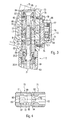
- the adjusting device 5 is preferably used as a mounting group in a housing of a piston engine.
- a first connection channel 12.1 and a second connection channel 12.2 are introduced in the housing of the piston engine.
- the first connection channel 12.1 and the second connection channel 12.2 are each closed on the outside of the housing by a sealing plug 66.
- the first connection channel 12.1 opens on the side of the adjusting device 5 on the housing so that it is in communication with the output terminal 10.
- the second connecting channel 12.2 opens out so that a connection with the actuating pressure chamber 8 is made.
- a plurality of connection openings 68 can be distributed over the circumference of the control piston 7, for example on the control piston 7.
- the adjusting piston 7 is provided at its outer periphery with a circumferential recess 67 in this area.
- the first connecting channel 12.1 and the second connecting channel 12.2 are supplemented by a receiving opening 69 to the connecting line 12, in which the combined throttle check valve 13 is arranged.
- the receiving opening 69 may be formed for example as a blind hole in the housing of the piston engine, wherein at least over a part of the length of the blind hole, an internal thread is formed.
- a first Gezzauseinpiceil 70 and a second Gepuruseinpiceil 71 is screwed.
- the first GeHouseinpiceil 70 and the throttle pin 72 is first used.
- the second Genzoinmagazineil 71 is screwed into the receiving opening 69 before the receiving opening 69 is also closed with a sealing plug 66.
- the throttle pin 72 has a conical portion which cooperates with a stopper to a throttle point, and is freely movable between two stops.
- the throttle pin 72 is held in abutment with the one stop or the other stop.
- a throttling cross section is released between the throttle pin 72 and the one stop, or a larger cross section is released, which generates an unthrottled or only slightly throttled connection between the first connecting channel 12.1 and the second connecting channel 12.2.
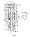
- FIG. 1 A second embodiment is shown in FIG.
- a valve receptacle 74 is arranged in the form of a recess in the housing 73, in which the adjusting device 5 is inserted with a part of its longitudinal extent.
- the adjusting piston 7 of the adjusting device 5 actuates due to its adjusting movement a swash plate 75, with which the delivery volume of the hydrostatic piston machine is adjusted.
- a mounting surface 76 is formed on which a housing 77 of the throttle check valve 13 is attached.
- the housing 77 of the throttle check valve 13 is secured by screws 78 to the housing 73 of the axial piston machine.
- a first housing channel 79.1 and a second housing channel 79.2 are introduced, which connect the valve receptacle 74 with the first connection channel 12.1 and the second connection channel 12.2, which in turn are provided in the housing 77 of the throttle check valve 13.
- the first and second housing channel 79.1 and 79.2 thus form, together with the first connection channel 12.1 and the second connection channel 12.2 and the two connection channels 12.1 and 12.2 connecting receiving opening 69, the connecting channel 12.
- a lubricating channel 80 is introduced on the piston shaft of the adjusting piston 7 at its outer circumference, which is connected to the actuating pressure chamber 8 via at least one lubrication bore 81.
- the control pressure prevailing in the control pressure chamber 8 ensures a low leakage flow in the gap formed between the control piston 7 and the valve seat 74, which serves for the lubrication of the control piston 7 slidably disposed in the valve seat 74.
- a retaining ring 82 is inserted into the actuating piston 7, which is penetrated by the coupling rod 21 as well as an adjacent disc 83.
- a support body 84 is supported, which has a corresponding to a spherical head 85 recess.
- the spherical head 85 is connected to the coupling rod 21 and is supported on the side facing away from the recess of the support body 84 on the actuating piston 7, so that between the coupling rod 21 and the actuating piston 7 both tensile and shear forces are transferable.
- a first recess 86 is arranged, which is designed stepped.
- the recess 86 is preferably rotationally symmetrical and penetrates the GeHouseinpiceil 70.
- a first stop 87 is formed on which a cylindrical portion 88 of the throttle pin 72 abuts when the throttle check valve 13 is in its open position.
- the cylindrical portion 88 has a diameter which is larger than the radially unextended portion of the recess 86, but smaller than the radially expanded portion of the recess 86, so that between the lateral surface of the cylindrical portion 88 of the throttle pin 72 and the first Genzouseinpiceil 70th a gap 91 is created.
- a transverse bore 89 and an associated longitudinal bore 90 introduced from the end face of the cylindrical part 88 are provided in the cylindrical part 88.
- a second recess 92 On the side of the first Genzouseinpiceils 70, at which the radially expanded portion of the recess 86 opens, connects to the recess 86, a second recess 92, which in turn is preferably rotationally symmetrical in the second Genzoinpiceil 71 and penetrates it.
- the second recess 92 also has at least one radial step, which forms a second stop 93, which is oriented opposite to the first stop 87. In the direction of the second stop 93, a frusto-conical part 94 adjoins the cylindrical part 88 of the throttle pin 72.
- the diameter of the radially unextended region of the second recess 92 is dimensioned so that the throttle pin 72 with the conical portion 94 partially in the radially unextended region of the second Recess 92 can dive, so that the lateral surface of the truncated cone comes into contact with the inner peripheral edge of the second stop 93.
- a plurality of flats 95 are formed on the circumference of the frusto-conical part 94. Due to the flats 95, the throttle pin 72 can not form a sealing seat on the second stop 93, but it forms a throttle point, whose cross section is preferably determined by the geometry of the flats 95.
- the gap 91 formed between the throttle pin 72 and the first housing insertion part 70 is continued.
- a throttling cross-section instead of the flats 95 on the conical portion 94 of the throttle pin 72 also z. B. notches on the second stop 93 be present.
- the throttle pin 72 can be exchanged for a different throttle pin after unscrewing the second GeHouseinjeeils 71 from the housing, not shown in FIG. 4. This can be adjusted individually when using different flats on the throttle pins each formed throttle point.
- FIG. 5 once again shows a schematic representation of the exemplary embodiment from FIG. 3, in which, however, a channel is provided in the valve sleeve 52 as connection point for the connecting line 12.
- the connection to the actuating pressure chamber 8 can thus be designed simply as a bore 99 running in the axial direction in the valve sleeve 52.
- To form the connecting line 12 is in turn in the housing 73 of the Piston engine, a first housing channel 79.1 and a second housing channel 79.2 are provided, which connect the valve receptacle 74 with the outside of the housing 73.
Landscapes
- Engineering & Computer Science (AREA)
- Mechanical Engineering (AREA)
- General Engineering & Computer Science (AREA)
- Fluid-Pressure Circuits (AREA)
- Reciprocating Pumps (AREA)
- Safety Valves (AREA)
Claims (11)
- Dispositif de régulation de puissance pour une machine à pistons hydrostatique variable, quant à son volume refoulé, au moyen d'un dispositif de positionnement (5), dans lequel une pression de positionnement qui agit dans le dispositif de positionnement (5) est susceptible d'être régulée par une valve de régulation de puissance (9) qui est reliée par une conduite de liaison (12) au dispositif de positionnement (5),
caractérisé en ce que
dans la conduite de liaison (12) sont prévus un clapet antiretour (15) et un étranglement (14) agencé parallèlement à celui-ci. - Dispositif de régulation de puissance selon la revendication 1,
caractérisé en ce que
la machine à pistons hydrostatique est déplacée lorsque la pression de positionnement augmente en direction d'une réduction du volume refoulé, et le clapet antiretour (15) est ouvert en direction du dispositif de positionnement (5). - Dispositif de régulation de puissance selon la revendication 1 ou 2,
caractérisé en ce que
la pression de positionnement est susceptible d'être régulée par la valve de régulation de puissance (9) en fonction du volume refoulé de la machine à pistons hydrostatique. - Dispositif de régulation de puissance selon l'une des revendications 1 à 3,
caractérisé en ce que
le clapet antiretour (15) et l'étranglement (14) sont réalisés sous forme de clapet combiné (13) antiretour à étranglement, qui comprend une tige d'étranglement mobile entre deux butées (87, 93). - Dispositif de régulation de puissance selon la revendication 4,
caractérisé en ce que
au moins une butée (93) forme, lorsque la tige d'étranglement (72) est appliquée, un étranglement (14) avec la tige d'étranglement (72). - Dispositif de régulation de puissance selon la revendication 5,
caractérisé en ce que
la tige d'étranglement (72) présente, dans une zone (94) qui coopère avec la butée (93) pour former un étranglement, une section essentiellement circulaire qui présente au moins un méplat (95) sur sa périphérie pour réaliser la section d'étranglement. - Dispositif de régulation de puissance selon l'une des revendications 4 à 6,
caractérisé en ce que
la tige d'étranglement (72) de la valve combinée (13) antiretour à étranglement est interchangeable et, par échange de la tige d'étranglement (72) il est possible de générer d'autres sections d'étranglement. - Dispositif de régulation de puissance selon l'une des revendications 4 à 7,
caractérisé en ce que
la tige d'étranglement (72) est précontrainte par un ressort dans la direction de fermeture du clapet antiretour (15). - Dispositif de régulation de puissance selon l'une des revendications 1 à 8,
caractérisé en ce que
la valve de régulation de puissance (9) est susceptible d'être mise en place au moins partiellement dans un évidement (74) d'un boîtier (73) d'une machine à pistons hydrostatique, des canaux (79.1, 79.2) étant prévus dans le boîtier, qui forment une partie de la conduite de liaison (12). - Dispositif de régulation de puissance selon la revendication 9,
caractérisé en ce que
les canaux (79.1, 79.2) s'étendent depuis l'évidement (74) de la machine à pistons hydrostatique jusqu'à un second évidement (69) qui est prévu pour loger le clapet combiné (13) antiretour à étranglement. - Dispositif de régulation de puissance selon la revendication 9,
caractérisé en ce que
les canaux (79.1, 79.2) débouchent, à leur extrémité détournée de l'évidement (74), à l'extérieur sur le boîtier (73), et une surface plane (76) est réalisée dans la zone de l'embouchure pour fixer le clapet combiné (13) antiretour à étranglement.
Applications Claiming Priority (2)
| Application Number | Priority Date | Filing Date | Title |
|---|---|---|---|
| DE10341331A DE10341331B3 (de) | 2003-09-08 | 2003-09-08 | Leistungsregelvorrichtung |
| PCT/EP2004/009643 WO2005028863A1 (fr) | 2003-09-08 | 2004-08-30 | Dispositif de regulation de puissance |
Publications (2)
| Publication Number | Publication Date |
|---|---|
| EP1664530A1 EP1664530A1 (fr) | 2006-06-07 |
| EP1664530B1 true EP1664530B1 (fr) | 2007-10-03 |
Family
ID=34352772
Family Applications (1)
| Application Number | Title | Priority Date | Filing Date |
|---|---|---|---|
| EP04764612A Expired - Lifetime EP1664530B1 (fr) | 2003-09-08 | 2004-08-30 | Dispositif de regulation de puissance |
Country Status (4)
| Country | Link |
|---|---|
| US (1) | US20060254269A1 (fr) |
| EP (1) | EP1664530B1 (fr) |
| DE (2) | DE10341331B3 (fr) |
| WO (1) | WO2005028863A1 (fr) |
Cited By (1)
| Publication number | Priority date | Publication date | Assignee | Title |
|---|---|---|---|---|
| CN110792584A (zh) * | 2019-11-27 | 2020-02-14 | 力源液压(苏州)有限公司 | 一种柱塞泵的多档输入功率控制系统 |
Families Citing this family (6)
| Publication number | Priority date | Publication date | Assignee | Title |
|---|---|---|---|---|
| DE102011076581A1 (de) | 2010-12-23 | 2012-06-28 | Robert Bosch Gmbh | Hydrostatische Kolbenmaschine mit Bremsvorrichtung |
| JP6021226B2 (ja) * | 2013-11-28 | 2016-11-09 | 日立建機株式会社 | 建設機械の油圧駆動装置 |
| DE102014206755B4 (de) | 2014-02-18 | 2024-09-19 | Robert Bosch Gmbh | Verstelleinrichtung einer Axialkolbenmaschine mit einem Druckmittel beaufschlagten Steuerventil |
| DE102014211202A1 (de) * | 2014-06-12 | 2015-12-17 | Robert Bosch Gmbh | Hydrostatische Axialkolbenmaschine in Schrägscheibenbauweise und Lüfter mit einer hydro-statischen Axialkolbenmaschine |
| JP6921071B2 (ja) | 2015-11-15 | 2021-08-18 | イートン インテリジェント パワー リミテッドEaton Intelligent Power Limited | 油圧ポンプ制御システム |
| CH717932A1 (de) * | 2020-10-06 | 2022-04-14 | Liebherr Machines Bulle Sa | Hydraulische Ventileinheit, Leistungs- und/oder Drehmomentregelungssystem und Axialkolbenmaschine mit einer solchen. |
Family Cites Families (7)
| Publication number | Priority date | Publication date | Assignee | Title |
|---|---|---|---|---|
| DE2121267A1 (de) * | 1971-04-30 | 1972-11-16 | G.L. Rexroth Gmbh, 8770 Lohr | Verstellpumpe mit Verstellvorrichtung |
| SE396239B (sv) * | 1976-02-05 | 1977-09-12 | Hytec Ab | Metod och anordning for reglering av den effekt som tillfors ett hydrauliskt, ett pneumatiskt eller ett hydraulpneumatiskt system |
| DE3345264A1 (de) * | 1983-12-14 | 1985-06-27 | Brueninghaus Hydraulik Gmbh, 7240 Horb | Drehmomenten-regeleinrichtung fuer eine verstellbare hydropumpe |
| US4821514A (en) * | 1987-06-09 | 1989-04-18 | Deere & Company | Pressure flow compensating control circuit |
| DE4302036C2 (de) * | 1993-01-26 | 1996-07-11 | Sauer Sundstrand Gmbh & Co | Als Wechseldrossel ausgeführtes Steuerorgan |
| DE19949169C2 (de) * | 1999-10-12 | 2001-10-11 | Brueninghaus Hydromatik Gmbh | Verstellvorrichtung |
| DE10001826C1 (de) * | 2000-01-18 | 2001-09-20 | Brueninghaus Hydromatik Gmbh | Vorrichtung zum Regeln der Leistung einer verstellbaren Kolbenmaschine |
-
2003
- 2003-09-08 DE DE10341331A patent/DE10341331B3/de not_active Expired - Fee Related
-
2004
- 2004-08-30 DE DE502004005162T patent/DE502004005162D1/de not_active Expired - Lifetime
- 2004-08-30 WO PCT/EP2004/009643 patent/WO2005028863A1/fr not_active Ceased
- 2004-08-30 US US10/571,201 patent/US20060254269A1/en not_active Abandoned
- 2004-08-30 EP EP04764612A patent/EP1664530B1/fr not_active Expired - Lifetime
Cited By (2)
| Publication number | Priority date | Publication date | Assignee | Title |
|---|---|---|---|---|
| CN110792584A (zh) * | 2019-11-27 | 2020-02-14 | 力源液压(苏州)有限公司 | 一种柱塞泵的多档输入功率控制系统 |
| CN110792584B (zh) * | 2019-11-27 | 2021-06-08 | 力源液压(苏州)有限公司 | 一种柱塞泵的多档输入功率控制系统 |
Also Published As
| Publication number | Publication date |
|---|---|
| DE502004005162D1 (de) | 2007-11-15 |
| WO2005028863A1 (fr) | 2005-03-31 |
| US20060254269A1 (en) | 2006-11-16 |
| EP1664530A1 (fr) | 2006-06-07 |
| DE10341331B3 (de) | 2005-05-25 |
Similar Documents
| Publication | Publication Date | Title |
|---|---|---|
| EP1409873B1 (fr) | Bloc de distribution pour un dispositif de regulation, en particulier une machine hydrostatique | |
| DE10115162C1 (de) | Druckbegrenzungsventil für Kraftstoff-Einspritzeinrichtungen | |
| DE3022918A1 (de) | Druck-uebersteuer-steuervorrichtung | |
| EP1853824B1 (fr) | Dispositif et procede pour une alimentation en lubrifiant | |
| DE102013216889B4 (de) | Überströmventil für ein Kraftstoffeinspritzsystem sowie Kraftstoffeinspritzsystem | |
| EP1664530B1 (fr) | Dispositif de regulation de puissance | |
| EP4357874A2 (fr) | Agencement de soupape | |
| EP1828651B1 (fr) | Soupape de limitation de pression presentant une surface differentielle reduite | |
| DE102009005768B4 (de) | Druckregelung einer hydraulischen Antriebseinheit | |
| EP1502027B1 (fr) | Dispositif de regulation comprenant une soupape de regulation de valeur limite | |
| DE3919175C2 (fr) | ||
| EP3464908B1 (fr) | Système de vannes | |
| DE102012214374B4 (de) | Druckbegrenzungsventil und hydrostatischer Fahrantrieb | |
| DE69615099T2 (de) | Durchfluss-Regeleinrichtung | |
| DE10261634B4 (de) | Kombinationsverschraubung für eine Vorrichtung zur Regelung des Flusses von Druckflüssigkeit in einer Durchfluss-Kontrolleinrichtung | |
| DE102009060188B4 (de) | Verstellventil für die Verstellung des Fördervolumens einer Verdrängerpumpe mit Kaltstartfunktion | |
| DE102022210469A1 (de) | Druckbegrenzungsventilanordnung, modulare Druckbegrenzungsventilanordnung und hydraulische Steueranordnung mit einer derartigen Druckbegrenzungsventilanordnung | |
| EP0636529B1 (fr) | Soupape de réglage de débit pour pompes de direction assistée | |
| DE19507975A1 (de) | Flügelzellenverdichter | |
| EP1174620B1 (fr) | Commande de pression dynamique | |
| DE102010044824B4 (de) | Ventil | |
| DE2424272C2 (de) | Hubventil | |
| DE3126794C2 (de) | Verstellpumpe | |
| WO2005057011A1 (fr) | Dispositif de regulation de puissance totale | |
| DE2519750A1 (de) | Hydraulikventil-baugruppe fuer fahrzeuge |
Legal Events
| Date | Code | Title | Description |
|---|---|---|---|
| PUAI | Public reference made under article 153(3) epc to a published international application that has entered the european phase |
Free format text: ORIGINAL CODE: 0009012 |
|
| 17P | Request for examination filed |
Effective date: 20050422 |
|
| AK | Designated contracting states |
Kind code of ref document: A1 Designated state(s): DE FR GB IT SE |
|
| GRAP | Despatch of communication of intention to grant a patent |
Free format text: ORIGINAL CODE: EPIDOSNIGR1 |
|
| DAX | Request for extension of the european patent (deleted) | ||
| RBV | Designated contracting states (corrected) |
Designated state(s): DE FR GB IT SE |
|
| GRAS | Grant fee paid |
Free format text: ORIGINAL CODE: EPIDOSNIGR3 |
|
| RIN1 | Information on inventor provided before grant (corrected) |
Inventor name: KAUSS, WOLFGANG Inventor name: LUDESCHER, HARALD Inventor name: BLUM, KARL-HEINZ |
|
| GRAA | (expected) grant |
Free format text: ORIGINAL CODE: 0009210 |
|
| AK | Designated contracting states |
Kind code of ref document: B1 Designated state(s): DE FR GB IT SE |
|
| REG | Reference to a national code |
Ref country code: GB Ref legal event code: FG4D Free format text: NOT ENGLISH |
|
| REG | Reference to a national code |
Ref country code: SE Ref legal event code: TRGR |
|
| GBT | Gb: translation of ep patent filed (gb section 77(6)(a)/1977) |
Effective date: 20071003 |
|
| REF | Corresponds to: |
Ref document number: 502004005162 Country of ref document: DE Date of ref document: 20071115 Kind code of ref document: P |
|
| ET | Fr: translation filed | ||
| PLBE | No opposition filed within time limit |
Free format text: ORIGINAL CODE: 0009261 |
|
| STAA | Information on the status of an ep patent application or granted ep patent |
Free format text: STATUS: NO OPPOSITION FILED WITHIN TIME LIMIT |
|
| 26N | No opposition filed |
Effective date: 20080704 |
|
| PGFP | Annual fee paid to national office [announced via postgrant information from national office to epo] |
Ref country code: SE Payment date: 20120823 Year of fee payment: 9 Ref country code: GB Payment date: 20120823 Year of fee payment: 9 |
|
| PGFP | Annual fee paid to national office [announced via postgrant information from national office to epo] |
Ref country code: IT Payment date: 20120824 Year of fee payment: 9 Ref country code: FR Payment date: 20120831 Year of fee payment: 9 |
|
| REG | Reference to a national code |
Ref country code: SE Ref legal event code: EUG |
|
| GBPC | Gb: european patent ceased through non-payment of renewal fee |
Effective date: 20130830 |
|
| PG25 | Lapsed in a contracting state [announced via postgrant information from national office to epo] |
Ref country code: SE Free format text: LAPSE BECAUSE OF NON-PAYMENT OF DUE FEES Effective date: 20130831 |
|
| REG | Reference to a national code |
Ref country code: FR Ref legal event code: ST Effective date: 20140430 |
|
| PG25 | Lapsed in a contracting state [announced via postgrant information from national office to epo] |
Ref country code: IT Free format text: LAPSE BECAUSE OF NON-PAYMENT OF DUE FEES Effective date: 20130830 |
|
| PG25 | Lapsed in a contracting state [announced via postgrant information from national office to epo] |
Ref country code: GB Free format text: LAPSE BECAUSE OF NON-PAYMENT OF DUE FEES Effective date: 20130830 |
|
| PG25 | Lapsed in a contracting state [announced via postgrant information from national office to epo] |
Ref country code: FR Free format text: LAPSE BECAUSE OF NON-PAYMENT OF DUE FEES Effective date: 20130902 |
|
| PGFP | Annual fee paid to national office [announced via postgrant information from national office to epo] |
Ref country code: DE Payment date: 20151022 Year of fee payment: 12 |
|
| REG | Reference to a national code |
Ref country code: DE Ref legal event code: R119 Ref document number: 502004005162 Country of ref document: DE |
|
| PG25 | Lapsed in a contracting state [announced via postgrant information from national office to epo] |
Ref country code: DE Free format text: LAPSE BECAUSE OF NON-PAYMENT OF DUE FEES Effective date: 20170301 |