EP1664528B1 - Blitzschutzverfahren für eine schaufel für eine windenergieanlage - Google Patents
Blitzschutzverfahren für eine schaufel für eine windenergieanlage Download PDFInfo
- Publication number
- EP1664528B1 EP1664528B1 EP04762822A EP04762822A EP1664528B1 EP 1664528 B1 EP1664528 B1 EP 1664528B1 EP 04762822 A EP04762822 A EP 04762822A EP 04762822 A EP04762822 A EP 04762822A EP 1664528 B1 EP1664528 B1 EP 1664528B1
- Authority
- EP
- European Patent Office
- Prior art keywords
- electrically conductive
- blade
- lightning
- receptor
- fibres
- Prior art date
- Legal status (The legal status is an assumption and is not a legal conclusion. Google has not performed a legal analysis and makes no representation as to the accuracy of the status listed.)
- Active
Links
- 238000000034 method Methods 0.000 title claims abstract description 27
- 229910052751 metal Inorganic materials 0.000 claims description 16
- 239000002184 metal Substances 0.000 claims description 14
- 239000003292 glue Substances 0.000 claims description 8
- 238000004026 adhesive bonding Methods 0.000 claims description 4
- 238000005476 soldering Methods 0.000 claims description 3
- BQCADISMDOOEFD-UHFFFAOYSA-N Silver Chemical compound [Ag] BQCADISMDOOEFD-UHFFFAOYSA-N 0.000 claims description 2
- 238000002347 injection Methods 0.000 claims description 2
- 239000007924 injection Substances 0.000 claims description 2
- 230000010354 integration Effects 0.000 claims description 2
- 239000011347 resin Substances 0.000 claims description 2
- 229920005989 resin Polymers 0.000 claims description 2
- 229910052709 silver Inorganic materials 0.000 claims description 2
- 239000004332 silver Substances 0.000 claims description 2
- 238000003466 welding Methods 0.000 claims description 2
- 239000000835 fiber Substances 0.000 abstract description 15
- OKTJSMMVPCPJKN-UHFFFAOYSA-N Carbon Chemical compound [C] OKTJSMMVPCPJKN-UHFFFAOYSA-N 0.000 description 11
- 229910052799 carbon Inorganic materials 0.000 description 11
- 239000003365 glass fiber Substances 0.000 description 5
- 229910000831 Steel Inorganic materials 0.000 description 4
- 239000010959 steel Substances 0.000 description 4
- 239000004020 conductor Substances 0.000 description 3
- 229910000906 Bronze Inorganic materials 0.000 description 1
- 230000000254 damaging effect Effects 0.000 description 1
- 238000009826 distribution Methods 0.000 description 1
- 238000004519 manufacturing process Methods 0.000 description 1
- 239000000463 material Substances 0.000 description 1
- 150000002739 metals Chemical class 0.000 description 1
- 239000000203 mixture Substances 0.000 description 1
- 238000010397 one-hybrid screening Methods 0.000 description 1
- 239000000243 solution Substances 0.000 description 1
Images


Classifications
-
- H—ELECTRICITY
- H02—GENERATION; CONVERSION OR DISTRIBUTION OF ELECTRIC POWER
- H02G—INSTALLATION OF ELECTRIC CABLES OR LINES, OR OF COMBINED OPTICAL AND ELECTRIC CABLES OR LINES
- H02G13/00—Installations of lightning conductors; Fastening thereof to supporting structure
-
- F—MECHANICAL ENGINEERING; LIGHTING; HEATING; WEAPONS; BLASTING
- F03—MACHINES OR ENGINES FOR LIQUIDS; WIND, SPRING, OR WEIGHT MOTORS; PRODUCING MECHANICAL POWER OR A REACTIVE PROPULSIVE THRUST, NOT OTHERWISE PROVIDED FOR
- F03D—WIND MOTORS
- F03D80/00—Details, components or accessories not provided for in groups F03D1/00 - F03D17/00
- F03D80/30—Lightning protection
-
- H—ELECTRICITY
- H02—GENERATION; CONVERSION OR DISTRIBUTION OF ELECTRIC POWER
- H02G—INSTALLATION OF ELECTRIC CABLES OR LINES, OR OF COMBINED OPTICAL AND ELECTRIC CABLES OR LINES
- H02G13/00—Installations of lightning conductors; Fastening thereof to supporting structure
- H02G13/40—Connection to earth
-
- H—ELECTRICITY
- H02—GENERATION; CONVERSION OR DISTRIBUTION OF ELECTRIC POWER
- H02G—INSTALLATION OF ELECTRIC CABLES OR LINES, OR OF COMBINED OPTICAL AND ELECTRIC CABLES OR LINES
- H02G13/00—Installations of lightning conductors; Fastening thereof to supporting structure
- H02G13/80—Discharge by conduction or dissipation, e.g. rods, arresters, spark gaps
-
- Y—GENERAL TAGGING OF NEW TECHNOLOGICAL DEVELOPMENTS; GENERAL TAGGING OF CROSS-SECTIONAL TECHNOLOGIES SPANNING OVER SEVERAL SECTIONS OF THE IPC; TECHNICAL SUBJECTS COVERED BY FORMER USPC CROSS-REFERENCE ART COLLECTIONS [XRACs] AND DIGESTS
- Y02—TECHNOLOGIES OR APPLICATIONS FOR MITIGATION OR ADAPTATION AGAINST CLIMATE CHANGE
- Y02E—REDUCTION OF GREENHOUSE GAS [GHG] EMISSIONS, RELATED TO ENERGY GENERATION, TRANSMISSION OR DISTRIBUTION
- Y02E10/00—Energy generation through renewable energy sources
- Y02E10/70—Wind energy
- Y02E10/72—Wind turbines with rotation axis in wind direction
Definitions
- the invention relates to a method of lightning-proofing a blade of a wind-energy plant, which blade comprises a blade shell configured essentially as a fibre-reinforced laminate, which laminate comprises electrically conductive fibres, where the blade comprises at least one lightning arrester configured for conducting a lightning current, including preferably to ground. Also, the invention relates to a lightning-proofed blade and a wind-energy plant.
- a method according to the invention as defined in claim 1 may at least partially remedy the above-described problems.
- the electrically conductive fibres are connected to each other by electrically conductive means, and the at least one essentially massive first connecting element of metal is arranged internally of the blade on top of the electrically conductive means and in electrically conductive connection therewith, said connecting element being connected to the lightning arrestor the fibres will cooperate on the conduction of a lightning current.
- a suitable electrical connection is accomplished, where powerful currents can be conducted from the electrically conductive means to the lightning arrester.
- any damaging effect will be reduced.
- the metallic receptor will serve as the primary lightning capturing device and reduce the risk of lightning strikes in the laminate.
- the receptor being connected to the lighting arrestor, the lightning current will predominately be earthed, while the risk of transfers to the laminate is minimised in that the electrically conductive fibres, being for the major part connected to each other, are also connected to the lightning arrestor whereby any difference in potential that may give rise to transfer is thereby equalised. The risk of lightning striking the laminate or transferring to the laminate from the lightning arrestor is thus minimised.
- the receptor can be connected both to the lightning arrestor and to the electrically conductive fibres in the principal laminate, either via the electrically conductive means or directly or by a combination thereof.
- the receptor which must always be of a sturdy configuration for conducting a lightning current, can also be used for connecting the conductive fibres in the laminate by means of the lightning conductor.
- a powerful current can also be conducted from the conductive fibres to the lightning arrester.
- the receptor can be connected to the electrically conductive fibres in the principal laminate by a process that comprises welding, soldering or gluing by electrically conductive glue, eg silver glue.
- electrically conductive glue eg silver glue.
- At least one further essentially massive connecting element of metal can be arranged against the laminate, and the electrically conductive means are arranged on top of the second connecting element, and the first connecting element is arranged on top of the electrically conductive means, and the first connecting element and the receptor are configured for being clamped to each other through the second connecting element and the electrically conductive means by threads.
- the first and the second connecting elements can be clamped around the electrically conductive means by means of the receptor, whereby good electrical connection is created from the electrically conductive means to the connecting elements.
- first connecting element and/or the second connecting element can be soldered, welded or glued with electrically conductive glue to the electrically conductive means for further improvement of the conductivity.
- the principal laminate may both comprise fibres that are electrically conductive and fibres that are not electrically conductive.
- the fibre composition can be optimised in relation to the design of the blade and the load on the blade, since one may freely select fibres from both categories.
- the receptor can be moulded completely or partially into the laminate, including eg in connection with vacuum-injection of resin for bonding the laminate.
- processing of the blade is avoided following setting for mounting of the receptor.
- the electrically conductive means may comprise electrically conductive fibres, including in the form of at least one mat. This is advantageous in that, usually, such fibres are already employed in the laminate, and thus they are readily available. Moreover the fibres can be laminated to each other, and a strength contribution there from can be used to advantage, if so desired.
- the electrically conductive means may comprise at least a grid or a plate of metal.
- good conductivity is accomplished of the conductive means that are thus suitable for conducting powerful currents.
- a number of elongate metal elements can be arranged at the exterior surface of the blade for capturing lightning current and connected to the lightning arrester.
- increased reliability is accomplished that a lightning current is captured and conduction of it to the lightning arrester without the laminate being influenced or damaged.
- the receptors can be arranged approximately symmetrically about an axis, which axis - seen in a cross section of the blade, essentially at right angles to the longitudinal axis of the blade from root to tip - extends through the fore edge and aft edge of the blade.
- advantageous distribution of the receptors is accomplished thereby increasing the likelihood of a lightning current being captured.
- the at least one receptor can be configured to be elongate and adapted for integration into or with the fore and/or aft edge(s) of the blade.
- the receptor or receptors can be configured to be elongate and adapted for integration into or with the fore and/or aft edge(s) of the blade.
- the receptor can be used as lightning arrester, at least along a part of the length of the blade.
- the receptor can be used as lightning arrester, at least along a part of the length of the blade.
- the at least one receptor can preferably be arranged at that part of the blade shell that is not constituted by the principal laminate of the blade, and preferably in a position in proximity of the principal laminate.
- the principal laminate is weakened - eg by through-bores, and the receptor can be arranged in the remaining part of the blade shell instead, which is less important from a strength point of view.
- the at least one receptor can preferably be arranged such that at least a part of the receptor is arranged in proximity of or at the external surface of the blade.
- a further aspect of the invention relates to a wind-energy plant comprising at least one lightning-proofed blade, which blade is manufactured according to a method according to one or more of the above aspects.
- a further aspect relates to a lightning-proofed blade, which blade is also manufactured according to a method according to one or more of the above aspects. In both cases corresponding advantages are accomplished that are disclosed in respective teachings above.
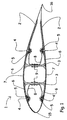
- FIG. 1 shows a blade 1 for a wind-energy plant.
- the blade 1 comprises a blade shell 2 that ia constitutes the aerodynamically active part of the blade.
- the blade shell 2 comprises upper principal laminates 7, by which the essential part of the strength and rigidity of the blade are achieved.
- two essentially longitudinally extending beams 3 are arranged for bracing purposes.
- the fore edge and the aft edge of the blade are indicated by reference numerals 15 and 16, respectively.
- metallic receptors 4 are provided at the exterior surface of the blade shell 2.
- the term "receptor" is to be understood an electrically conductive object being configured with a view to capturing and conducting a lightning current.
- connection 8 the receptors 4 are connected to lightning arresters 9.
- Receptors 4, connections 8 and arresters 9 are metallic objects configured for being able to conduct a lightning current that may be extremely powerful. The lightning current must be conducted reliably from the lightning currents 9 to a ground connection, including optionally across a spark gap since otherwise the current may damage the blade.
- the receptors 4 are connected to connections 8 by terminals 5 that are configured for reliably transferring a lightning current from the receptor 4 to the connection 8.
- the principal laminates 7 comprise not shown electrically conductive fibres, such as carbon fibres, steel fibres, etch.
- Electrically conductive means 6 are arranged that are connected to a large portion of the conductive fibres in principal laminates, and being in the shown case connected to a lightning arrester 9 via a receptor 4 and a connection 8. This is a practical embodiment, the receptor being already connected to the lightning arrestor 9; however, the conductive means 6 may also be connected to a lightning arrestor in some other manner.
- the conductive means 6 and hence the conductive fibres are connected to the lightning arrester 6, the fibres, the conductive means and the lightning arrester will have the same potential, thereby at least reducing the risk of a lightning current in the lightning arrestor transferring to the fibres of the laminate 7.
- the receptors 4 are preferably arranged next to the principal laminates 7 so as not to compromise the strength thereof. The number and location of the receptors 4 are selected to be in accordance with the dimensions of the blade 1.
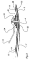
- FIG. 2 shows a blade shell 2 comprising a principal laminate 7, wherein not shown electrically conductive fibres are shown.
- a cylindrical receptor 4 is provided next to the principal laminate 7, a cylindrical receptor 4 is provided.
- a metallic connecting element 10 is arranged that may be secured by means of glue.
- a heavy grid 12 of cupper is provided: the grid 12 is conveyed across a part of the principal laminate 7 where it is in contact with the not shown electrically conductive fibres - either directly or by means of not shown electrically conductive means.
- a number of mats 13 are arranged that may be of carbon fibres or other suitable material, and yet a grid of cupper.
- a metallic connecting element 11 provided with thread is arranged on top of the layers of grid 12 and mats 13, yet a metallic connecting element 11 provided with thread is arranged.
- the receptor 4 is also configured with threads for cooperating with the connecting element 11 through the connecting element 10, grid 12 and mats 13.
- clamping together of the receptor 4 and the connecting element 11 can be used to clamp the connecting elements 10, 11 tightly around grid 12 and mats 13, whereby good electrical connection is achieved. This can be further improved and ensured by soldering the grids 12 to the respective connecting elements 10 and 11.
- the receptor 4 is connected to a connection 8 for earthing. To improve securing of connection 8, it is arranged in a gluing 14.
- the metallic connecting elements 10 and 11 can be configured of eg a bronze-alloy; but other metals may also be used. The same applies to grids 12 and mats 13; the essential being good electrical conductivity.
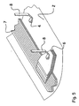
- Figure 3 shows an exemplified embodiment of mats 13 and grids 12, wherein they are stepped up in thickness and narrowed in width in the course from the laminate 7 towards the connecting element 11.
- the one grid 12 is arranged in contact with not shown electrically conductive fibres in the laminate 7, and the grids 12 and the mats 13 thus constitute electrically conductive means 6 that also connect the conductive fibres to each other.
- Figure 4 shows a receptor 4 cast integrally with a laminate for a blade. Exteriorly a layer of gel coat 10 is provided.
- the laminate comprises electrically non-conductive fibres 20 in mat-shape and electrically conductive fibres 21 arranged in mats 18. Both fibres 20 and fibres 21 are arranged in batches 18, wherein the binding ensures electrically conductive connection between all of the fibres, albeit they are situated essentially in parallel.
- the receptor 4 is connected to the fibres 21 by electrically conductive glue 22.
- a connection 8 is coupled to a not shown lightning arrester for earthing and by means of a screw it is connected to the receptor 4, whereby both receptor 4 and electrically conductive fibres 21 are connected to ground.
- the shown fibre mats may conveniently be the so-called hybrid mats that are structured in a pattern with at least one roving of one type of fibre and at least one roving of another type of fibre.
- the fibres 20 can have a pattern of alternately seven rovings of glass fibres and one roving of carbon fibres.
- electrically conductive means are arranged, eg in the form of electrically conductive fibres, eg carbon fibres, for creating an electrical connection and equalisation of potential between the fibres.
- the electrically conductive means can be a metal grid or a metal plate or the like.
- Fibres 21 may be steel fibres.
- FIG. 5 shows a blade shell 2 comprising a laminate 7 that contains not shown electrically conductive fibres, said fibres being electrically connected via electrically conductive means 6 from where they are coupled to a connection 8.
- a receptor 4 is arranged that is connected to a connection 8. Both connections 8 are connected to ground.
- Figure 6 shows a blade shell 2, wherein a receptor 4 is arranged for capturing lightnings at the outside at the outside thereof, and wherein the receptor is arranged in that part of the blade shell that is not constituted by the principal laminate 7. Via a connection 8, the receptor 4 is connected to ground. Not shown electrically conductive fibres in the laminate 7 are connected to a grid 13 of metal and likewise connected to the connection 8. Preferably the grid can be glued to the laminate.
- Figure 7 shows a principal laminate 7 containing at least a portion of not shown electrically conductive fibres, eg in the form of at least one hybrid mat, wherein the fibres are connected to electrically conductive means 6.
- the means 6 can be a grid, a mat or a plate and configured essentially of an electrically conductive material.
- the electrically conductive fibres can be cross-connected by electrically conductive means throughout the entire length of the blade or in sections.
- Figure 8 shows a blade shell 2 with internal bracings in the form of beams 3. Exteriorly of the blade shell 2, elongate metal members 23 are arranged - the so-called diverter strips - that are connected to a receptor 4. Hereby great area coverage of the surface is accomplished by means of relatively few receptors 4, which may be advantageous in case of large blades.
- the metal objects 23 can be secured by gluing or cast integrally.
- Figure 9 shows bracing beams 3 and receptors 24 and 25 that can be integral with the fore edge and/or the aft edge of the blade and will have an expanse corresponding at least to half the length of the blade.
Claims (18)
- Verfahren zur Blitzschutzausstattung eines Rotorblatts (1) einer Windkraftanlage, wobei das Rotorblatt eine Rotorblatthülle (2) besitzt, die mindestens ein faserverstärktes Hauptlaminat (7; 18) aufweist, wobei das Hauptlaminat elektrisch leitfähige Fasern (21) aufweist und wobei das Rotorblatt mindestens einen Überspannungsableiter (9) aufweist, der zum Leiten von Blitzströmen, einschließlich vorzugsweise zur Erde, konfiguriert ist,
wobei das Verfahren folgende Schritte aufweist:- mindestens eine Anzahl von elektrisch leitfähigen Fasern innerhalb desselben Hauptlaminats wird durch elektrisch leitfähige Einrichtungen (6,12, 13) miteinander verbunden; und- mindestens ein metallischer Rezeptor (4, 24, 25) wird zum Auffangen von Blitzströmen an der oder in der Nähe der äußeren Oberfläche des Rotorblatts vorgesehen; und- der Rezeptor wird mit dem Überspannungsableiter verbunden; und- eine Anzahl der elektrisch leitfähigen Fasern innerhalb desselben Hauptlaminats wird über die elektrisch leitfähigen Einrichtungen mit dem Überspannungsableiter verbunden, um die Potentialdifferenz zwischen dem Überspannungsableiter und den elektrisch leitfähigen Fasern auszugleichen,wobei mindestens ein im wesentlichen massives erstes Verbindungselement (11) aus Metall im Inneren des Rotorblatts oben auf den elektrisch leitfähigen Einrichtungen sowie in elektrisch leitender Verbindung mit diesen angeordnet wird, wobei das Verbindungselement mit dem Überspannungsableiter in Verbindung steht. - Verfahren nach Anspruch 1,
wobei der Rezeptor sowohl mit dem Überspannungsableiter als auch mit den elektrisch leitfähigen Fasern in dem Hauptlaminat entweder über die elektrisch leitfähigen Einrichtungen oder direkt durch eine Kombination von diesen verbunden wird. - Verfahren nach Anspruch 1 oder 2,
wobei der Rezeptor mit den elektrisch leitfähigen Fasern in dem Hauptlaminat durch einen Vorgang verbunden wird, der Schweißen, Löten oder Kleben mittels elektrisch leitfähigen Klebstoffs, beispielsweise Silberklebstoff, beinhaltet. - Verfahren nach Anspruch 1,
wobei mindestens ein zweites im wesentlichen massives Verbindungselement (10) aus Metall in Anlage an dem Laminat angeordnet wird;
und wobei die elektrisch leitfähigen Einrichtungen oben auf dem weiteren Verbindungselement angeordnet werden;
und wobei das erste Verbindungselement (11) oben auf den elektrisch leitfähigen Einrichtungen angeordnet wird;
und wobei das erste Verbindungselement und der Rezeptor dazu ausgebildet sind, durch das zweite Verbindungselement und die elektrisch leitfähigen Einrichtungen mittels Gewindeeinrichtungen gegeneinander geklemmt zu werden. - Verfahren nach einem oder mehreren der Ansprüche 1-4,
wobei das erste Verbindungselement und/oder das zweite Verbindungselement mit den elektrisch leitfähigen Einrichtungen verlötet, verschweißt oder mittels elektrisch leitfähigen Klebstoffs verklebt ist/sind. - Verfahren nach einem oder mehreren der Ansprüche 1 bis 5,
wobei das Hauptlaminat sowohl elektrisch leitfähige Fasern als auch elektrisch nicht leitfähige Fasern (20) aufweist. - Verfahren nach einem oder mehreren der Ansprüche 1 bis 6,
wobei der Rezeptor vollständig oder teilweise integral mit dem Laminat gegossen wird, beispielsweise in Verbindung mit einem Vakuumeinspritzvorgang von Harz zum Verbinden des Laminats. - Verfahren nach einem oder mehreren der Ansprüche 1 bis 7,
wobei die elektrisch leitfähigen Einrichtungen elektrisch leitfähige Fasern einschließlich solchen in Form von mindestens einer Matte aufweisen. - Verfahren nach einem oder mehreren der Ansprüche 1 bis 8,
wobei die elektrisch leitfähigen Einrichtungen zumindest ein Gitter oder eine Platte aus Metall aufweisen. - Verfahren nach einem oder mehreren der Ansprüche 1 bis 9,
wobei eine Anzahl von langgestreckten Metallelementen (23) an der äußeren Oberfläche des Rotorblatts angeordnet wird, um Blitzströme aufzufangen, sowie mit dem Überspannungsableiter verbunden wird. - Verfahren nach einem oder mehreren der Ansprüche 1 bis 10,
wobei eine Anzahl von Rezeptoren sowohl an der Oberseite als auch an der Unterseite des Rotorblatts angeordnet wird. - Verfahren nach Anspruch 11,
wobei die Rezeptoren etwa asymmetrisch um eine Achse angeordnet werden, wobei die Achse im Querschnitt des Rotorblatts im wesentlichen rechtwinklig zu der Längsachse des Rotorblatts von der Wurzel bis zu der Spitze durch den vorderen Rand (15) und den hinteren Rand (16) des Rotorblatts hindurchgeht. - Verfahren nach einem oder mehrere der Ansprüche 1 bis 10,
wobei der mindestens eine Rezeptor langgestreckt konfiguriert sowie für die Integration in dem oder mit dem vorderen und/oder dem hinteren Rand des Rotorblatts ausgebildet wird. - Verfahren nach Anspruch 13,
wobei der Rezeptor zumindest an einem Teil der Länge des Rotorblatts als Überspannungsableiter verwendet wird. - Verfahren nach einem oder mehreren der Ansprüche 1 bis 14,
wobei der mindestens eine Rezeptor vorzugsweise an dem Teil des Rotorblattshülle verwendet wird, der nicht durch das Hauptlaminat des Rotorblatts gebildet ist, vorzugsweise an einer Stelle in der Nähe des Hauptlaminats. - Verfahren nach einem oder mehreren der Ansprüche 1 bis 15,
wobei der mindestens eine Rezeptor vorzugsweise derart angeordnet wird, daß zumindest ein Teil des Rezeptors in der Nähe von der oder an der Außenfläche des Rotorblatts angeordnet ist. - Windkraftanlage mit mindestens einem mit Blitzschutz versehenen Rotorblatt (1), wobei das Rotorblatt eine Rotorblatthülle (2) besitzt, die mindestens ein faserverstärktes Hauptlaminat (7, 18) aufweist, wobei das Hauptlaminat elektrisch leitfähige Fasern (21) aufweist, wobei das Rotorblatt mindestens einen Überspannungsableiter (9) aufweist, der zum Leiten von Blitzströmen, einschließlich vorzugsweise zur Erde, konfiguriert ist, wobei das Rotorblatt mit einem Verfahren nach einem der Ansprüche 1 bis 16 hergestellt ist, wobei mindestens eine Anzahl der elektrisch leitfähigen Fasern innerhalb desselben Hauptlaminats durch elektrisch leitfähige Einrichtungen (6,12, 13) miteinander verbunden sind, und wobei mindestens ein Rezeptor (4, 24, 25) zum Auffangen von Blitzströmen an der oder in der Nähe der äußeren Oberfläche des Rotorblatts angeordnet ist;
und wobei der Rezeptor mit dem Überspannungsableiter verbunden ist und eine Anzahl der elektrisch leitfähigen Fasern innerhalb desselben Hauptlaminats über die elektrisch leitfähigen Einrichtungen mit dem Überspannungsableiter verbunden ist, um die Potentialdifferenz zwischen dem Überspannungsableiter und den elektrisch leitfähigen Fasern auszugleichen, dadurch gekennzeichnet,
daß mindestens ein im wesentlichen massives erstes Verbindungselement (11) aus Metall im Inneren des Rotorblatts oben auf den elektrisch leitfähigen Einrichtungen sowie in elektrisch leitender Verbindung mit diesen angeordnet ist, wobei das Verbindungselement mit dem Überspannungsableiter in Verbindung steht, und daß der Rezeptor metallisch ist. - Mit Blitzschutz versehenes Rotorblatt (1) für eine Windkraftanlage, wobei das Rotorblatt eine Rotorblatthülle (2) besitzt, die mindestens ein faserverstärktes Hauptlaminat (7, 18) aufweist, wobei das Hauptlaminat elektrisch leitfähige Fasern (21) aufweist, wobei das Rotorblatt mindestens einen Überspannungsableiter (9) aufweist, der zum Leiten von Blitzströmen, einschließlich vorzugsweise zur Erde, konfiguriert ist,
wobei das Rotorblatt mit einem Verfahren nach einem der Ansprüche 1 bis 16 hergestellt ist,
wobei mindestens eine Anzahl der elektrisch leitfähigen Fasern innerhalb desselben Hauptlaminats durch elektrisch leitfähige Einrichtungen (6,12, 13) miteinander verbunden sind,
und wobei mindestens ein Rezeptor (4, 24, 25) zum Auffangen von Blitzströmen an der oder in der Nähe der äußeren Oberfläche des Rotorblatts angeordnet ist;
und wobei der Rezeptor mit dem Überspannungsableiter verbunden ist und eine Anzahl der elektrisch leitfähigen Fasern innerhalb desselben Hauptlaminats über die elektrisch leitfähigen Einrichtungen mit dem Überspannungsableiter verbunden ist, um die Potentialdifferenz zwischen dem Überspannungsableiter und den elektrisch leitfähigen Fasern auszugleichen, dadurch gekennzeichnet,
daß mindestens ein im wesentlichen massives erstes Verbindungselement (11) aus Metall im Inneren des Rotorblatts oben auf den elektrisch leitfähigen Einrichtungen sowie in elektrisch leitender Verbindung mit diesen angeordnet ist, wobei das Verbindungselement mit dem Überspannungsableiter in Verbindung steht, und daß der Rezeptor metallisch ist.
Applications Claiming Priority (2)
| Application Number | Priority Date | Filing Date | Title |
|---|---|---|---|
| DK200301329A DK176298B1 (da) | 2003-09-15 | 2003-09-15 | Metode til lynsikring af en vinge til et vindenergianlæg, en lynsikret vinge samt et vindenergianlæg med en sådan vinge |
| PCT/DK2004/000602 WO2005026538A1 (en) | 2003-09-15 | 2004-09-10 | A method of lightning-proofing a blade for a wind-energy plant |
Publications (3)
| Publication Number | Publication Date |
|---|---|
| EP1664528A1 EP1664528A1 (de) | 2006-06-07 |
| EP1664528B1 true EP1664528B1 (de) | 2010-12-29 |
| EP1664528B2 EP1664528B2 (de) | 2019-11-27 |
Family
ID=34306688
Family Applications (1)
| Application Number | Title | Priority Date | Filing Date |
|---|---|---|---|
| EP04762822.7A Active EP1664528B2 (de) | 2003-09-15 | 2004-09-10 | Blitzschutzverfahren für eine schaufel für eine windenergieanlage |
Country Status (10)
| Country | Link |
|---|---|
| US (1) | US7651320B2 (de) |
| EP (1) | EP1664528B2 (de) |
| CN (1) | CN100425828C (de) |
| AT (1) | ATE493581T1 (de) |
| AU (1) | AU2004272684B2 (de) |
| CA (1) | CA2538140C (de) |
| DE (1) | DE602004030806D1 (de) |
| DK (1) | DK176298B1 (de) |
| ES (1) | ES2358671T5 (de) |
| WO (1) | WO2005026538A1 (de) |
Cited By (12)
| Publication number | Priority date | Publication date | Assignee | Title |
|---|---|---|---|---|
| EP2543874A1 (de) | 2011-07-06 | 2013-01-09 | LM Wind Power A/S | Windturbinenschaufel |
| EP2930010A1 (de) | 2014-04-10 | 2015-10-14 | Nordex Energy GmbH | Gurtbaugruppe für ein Windenergieanlagenrotorblatt |
| EP2930352A1 (de) | 2014-04-10 | 2015-10-14 | Nordex Energy GmbH | Windenergieanlagenrotorblatt mit einer Potentialausgleichsanordnung |
| EP2930353A1 (de) | 2014-04-10 | 2015-10-14 | Nordex Energy GmbH | Windenergieanlagenrotorblatt mit einer Potentialausgleichsanordnung |
| DE102016001734A1 (de) * | 2015-11-19 | 2017-05-24 | DEHN + SÖHNE GmbH + Co. KG. | Verfahren zur Beeinflussung der Blitzstromverteilung in elektrischen Systemen, welche in Rotorblätter von Windkraftanlagen integriert sind |
| EP3339633A1 (de) | 2016-12-22 | 2018-06-27 | Nordex Energy GmbH | Verfahren zur herstellung einer potentialausgleichsverbindung an einem windenergieanlagenrotorblatt und windenergieanlagenrotorblatt mit einer potentialausgleichsverbindung |
| EP3339632A1 (de) | 2016-12-22 | 2018-06-27 | Nordex Energy GmbH | Anschluss- und befestigungseinheit für einen blitzrezeptor zur integration in ein windenergieanlagenrotorblatt |
| EP3611373A1 (de) | 2018-08-15 | 2020-02-19 | LM Wind Power International Technology II ApS | Blitzableiterklammer |
| US10584684B2 (en) | 2015-12-23 | 2020-03-10 | Lm Wp Patent Holding A/S | Wind turbine blades and potential equalization systems |
| WO2020115198A1 (en) | 2018-12-05 | 2020-06-11 | Lm Wind Power A/S | Attachment to a sandwich structure element |
| EP3967869A1 (de) | 2020-09-14 | 2022-03-16 | Siemens Gamesa Renewable Energy A/S | Windturbinenblatt, windturbine, verfahren zur herstellung eines windturbinenkomponente und verfahren zur herstellung einer windturbinenschaufel |
| US11286912B2 (en) | 2017-08-25 | 2022-03-29 | Wobben Properties Gmbh | Wind turbine rotor blade and lightning protection system for a wind turbine rotor blade |
Families Citing this family (78)
| Publication number | Priority date | Publication date | Assignee | Title |
|---|---|---|---|---|
| CA2543551C (en) * | 2003-10-31 | 2011-09-06 | Vestas Wind Systems A/S | Member for potential equalising |
| WO2006051147A1 (es) * | 2004-11-11 | 2006-05-18 | Gamesa Innovation And Technology, S.L. | Sistema pararrayos para pala de aerogenerador con laminados de fibra de carbono |
| ES2255436B1 (es) * | 2004-11-11 | 2007-07-01 | Gamesa Eolica, S.A. | Sistema pararrayos para pala de aerogenerador con laminados de fibra de carbono. |
| ES2255454B1 (es) | 2004-12-15 | 2007-07-01 | Gamesa Eolica, S.A. | Sistema pararrayos para pala de aerogenerador. |
| DE102005047959B4 (de) * | 2005-10-06 | 2008-01-31 | Nordex Energy Gmbh | Verfahren zur Herstellung einer Durchführung in einem Faserverbundwerkstoff sowie Rotorblatt für eine Windenergieanlage mit einer Durchführung |
| JP4969098B2 (ja) | 2005-12-21 | 2012-07-04 | 三菱重工業株式会社 | 風車翼の落雷保護装置、該落雷保護装置の組立方法、該落雷保護装置を備える風車翼、及び該風車翼を備える風車 |
| JP4699255B2 (ja) | 2006-03-24 | 2011-06-08 | 三菱重工業株式会社 | 風車翼 |
| DK200600653A (da) * | 2006-05-09 | 2007-11-10 | Vestas Wind Sys As | Lynbeskyttelsesanlæg til en vindmöllevinge, og fremgangsmåde til fremstilling af en vindmöllevinge med et lynbeskyttelsessystem |
| GB0609166D0 (en) * | 2006-05-09 | 2006-06-21 | Airbus Uk Ltd | Apparatus for and method of inhibiting delamination |
| DK2122162T3 (da) | 2007-02-19 | 2017-08-21 | Vestas Wind Sys As | Vindmøllerotorvinge og fremgangsmåde til fremstilling af sådan rotorvinge |
| FR2914622B1 (fr) * | 2007-04-04 | 2009-05-15 | Airbus France Sas | Aeronef comprenant une structure assurant les fonctions structurale et electrique |
| FR2924687B1 (fr) | 2007-12-11 | 2010-05-07 | Airbus France | Systeme parafoudre et aeronef comportant un tel systeme |
| US20110020134A1 (en) * | 2007-12-20 | 2011-01-27 | Vestas Wind Systems A/S | Lightning receptors comprising carbon nanotubes |
| US20090167024A1 (en) * | 2007-12-28 | 2009-07-02 | Thorsten Landau | Gluing of wind turbine internals to structural components |
| US8182227B2 (en) * | 2008-02-01 | 2012-05-22 | General Electric Company | Wind turbine blade with lightning receptor |
| EP2110552B2 (de) * | 2008-04-15 | 2018-12-26 | Siemens Aktiengesellschaft | Windturbinenschaufel mit integriertem Blitzableiter und Verfahren zu seiner Herstellung |
| ATE535711T1 (de) * | 2008-07-02 | 2011-12-15 | Siemens Ag | Windturbinenschaufel mit blitzrezeptor und verfahren zum schutz der oberfläche einer windturbinenschaufel |
| US8137074B2 (en) | 2008-08-21 | 2012-03-20 | General Electric Company | Wind turbine lightning protection system |
| US7942640B2 (en) * | 2009-03-19 | 2011-05-17 | General Electric Company | Method and apparatus for use in protecting wind turbine blades from lightning damage |
| KR101711226B1 (ko) * | 2009-04-17 | 2017-02-28 | 쓰리엠 이노베이티브 프로퍼티즈 컴파니 | 패턴화된 전도체를 갖는 낙뢰 보호 시트 |
| BRPI1006590B1 (pt) * | 2009-04-17 | 2020-04-14 | 3M Innovative Properties Co | revestimento de proteção contra raios |
| US8342805B2 (en) * | 2009-06-25 | 2013-01-01 | General Electric Company | Transversal conduction lightning protection system |
| GB0912016D0 (en) * | 2009-07-10 | 2009-08-19 | Airbus Operations Ltd | Edge glow protection for composite component |
| MX2011013647A (es) * | 2009-12-24 | 2012-01-19 | Mitsubishi Heavy Ind Ltd | Aspa de turbina eolica y generador de turbina eolica que tiene la misma. |
| JP2011137386A (ja) * | 2009-12-25 | 2011-07-14 | Mitsubishi Heavy Ind Ltd | 風車回転翼および風車回転翼の製造方法 |
| CN101793239A (zh) * | 2010-03-19 | 2010-08-04 | 昆山华风风电科技有限公司 | 风力发电机组风叶的避雷装置 |
| DE102010025546A1 (de) * | 2010-06-29 | 2011-12-29 | Suzlon Energy Gmbh | Maschinenhausverkleidung |
| EP2596239A4 (de) | 2010-07-23 | 2014-06-25 | Erico Int Corp | Aufnahme für den blitzschutz einer windturbinenschaufel |
| ES2396839B1 (es) * | 2010-11-30 | 2014-01-02 | Gamesa Innovation & Technology, S.L. | Sistema pararrayos para pala de aerogenerador con laminados de fibra de carbono. |
| US20110142671A1 (en) * | 2010-12-01 | 2011-06-16 | General Electric Company | Wind turbine rotor blades with enhanced lightning protection system |
| US8096765B2 (en) * | 2010-12-01 | 2012-01-17 | General Electric Company | Wind turbine rotor blades with enhanced lightning protection system |
| CN102536677A (zh) * | 2010-12-22 | 2012-07-04 | 上海艾郎风电科技发展有限公司 | 风力发电的叶片避雷装置 |
| DE102011079240B4 (de) * | 2011-07-15 | 2018-09-06 | Carbon Rotec Gmbh & Co. Kg | Einrichtung und Verfahren zur Fertigung eines Bauteils |
| US8834117B2 (en) * | 2011-09-09 | 2014-09-16 | General Electric Company | Integrated lightning receptor system and trailing edge noise reducer for a wind turbine rotor blade |
| EP2649690B1 (de) * | 2011-12-09 | 2016-03-23 | MITSUBISHI HEAVY INDUSTRIES, Ltd. | Windturbinenschaufel |
| CN102497715A (zh) * | 2011-12-13 | 2012-06-13 | 湘电风能有限公司 | 风力发电机组叶片的静电释放装置 |
| CN102661240A (zh) * | 2012-05-16 | 2012-09-12 | 国电联合动力技术有限公司 | 一种风力发电机组风轮叶片防雷装置及其安装方法 |
| CA2878999A1 (en) * | 2012-08-06 | 2014-02-13 | Wobben Properties Gmbh | Cfrp resistive sheet heating |
| US10427363B2 (en) | 2013-02-13 | 2019-10-01 | Vestas Wind Systems A/S | Wind turbine blade having a lightning protection system and method of making the same |
| DE102013107296B4 (de) | 2013-07-10 | 2015-03-19 | Senvion Se | Rotorblatt mit Blitzableiter |
| EP3024645B1 (de) * | 2013-07-26 | 2023-11-29 | LM Wind Power A/S | Verfahren zur herstellung mindestens eines teils eines windturbinenblattes |
| GB2519332A (en) * | 2013-10-17 | 2015-04-22 | Vestas Wind Sys As | Improvements relating to lightning protection systems for wind turbine blades |
| GB2521809A (en) * | 2013-10-17 | 2015-07-08 | Vestas Wind Sys As | Improvements relating to lightning protection systems for wind turbine blades |
| GB2519331A (en) * | 2013-10-17 | 2015-04-22 | Vestas Wind Sys As | Improvements relating to lightning protection systems for wind turbine blades |
| FR3012527B1 (fr) * | 2013-10-30 | 2015-10-30 | Snecma | Metallisation d'un carter electriquement isolant d'un moteur aeronautique |
| US9702255B2 (en) | 2013-11-26 | 2017-07-11 | Textron Innovations, Inc. | Propeller with lightening strike protection |
| EP2930355B1 (de) * | 2014-04-10 | 2018-08-01 | Nordex Energy GmbH | Windenergieanlagenrotorblatt mit einem Blitzschutzleiter und einem Potentialausgleichselement |
| ES2686707T3 (es) * | 2014-04-10 | 2018-10-19 | Nordex Energy Gmbh | Pala de rotor de turbina eólica con una base de receptor de rayos |
| US10316827B2 (en) * | 2014-11-11 | 2019-06-11 | General Electric Company | Conduit assembly for a lightning protection cable of a wind turbine rotor blade |
| US9816482B2 (en) * | 2014-11-17 | 2017-11-14 | General Electric Company | Spar cap for a wind turbine rotor blade |
| US9759183B2 (en) * | 2015-01-05 | 2017-09-12 | General Electric Company | System and method for attaching components to a web in a wind turbine rotor blade |
| JP6444797B2 (ja) * | 2015-03-31 | 2018-12-26 | 株式会社東芝 | 風力発電システム |
| ES2589185B1 (es) * | 2015-05-08 | 2017-09-18 | Gamesa Innovation & Technology, S.L. | Sistema pararrayos para palas de aerogeneradores con componentes estructurales conductores |
| US9719495B2 (en) | 2015-05-13 | 2017-08-01 | General Electric Company | Lightning protection system for wind turbine rotor blades |
| ES2592323B1 (es) | 2015-05-26 | 2017-09-18 | Gamesa Innovation & Technology, S.L. | Receptor de rayos para una pala de aerogenerador |
| US20180245566A1 (en) * | 2015-08-24 | 2018-08-30 | Hitachi, Ltd. | Wind Power Generation Device |
| CN108603487B (zh) | 2016-01-29 | 2021-06-29 | 乌本产权有限公司 | 梁帽和制造方法 |
| USD803163S1 (en) | 2016-05-13 | 2017-11-21 | Erico International Corporation | Tip receptor mount for lightning protection systems |
| US10344743B2 (en) | 2016-05-13 | 2019-07-09 | Erico International Corporation | Lightning protection system and method for wind turbine blades |
| ES2646015B1 (es) | 2016-06-07 | 2018-09-20 | Gamesa Innovation & Technology, S.L. | Sistema pararrayos para palas de aerogeneradores con medios optimizados de inyección de corrientes de rayo en los componentes conductores de sus conchas. |
| US10648456B2 (en) * | 2016-10-21 | 2020-05-12 | General Electric Company | Organic conductive elements for deicing and lightning protection of a wind turbine rotor blade |
| ES2687782A1 (es) * | 2017-04-28 | 2018-10-29 | Gamesa Innovation & Technology, S.L. | Método y sistema de evaluación de un sistema pararrayos de un aerogenerador que comprende una pluralidad de palas fabricadas con un compuesto reforzado con fibra de carbono |
| ES2898689T3 (es) * | 2017-12-13 | 2022-03-08 | Nordex Energy Se & Co Kg | Concha de pala de rotor para una pala de rotor y procedimiento para fabricar una concha de pala de rotor para una pala de rotor |
| ES2914318T3 (es) * | 2018-06-14 | 2022-06-09 | Siemens Gamesa Renewable Energy As | Interfaz de conductividad escalonada |
| JP6657314B2 (ja) * | 2018-06-15 | 2020-03-04 | 三菱重工業株式会社 | 風車翼保護構造及びその形成方法 |
| US11644011B2 (en) | 2018-07-09 | 2023-05-09 | Vestas Wind Systems A/S | Relating to wind turbine blades |
| DK3597911T3 (da) * | 2018-07-17 | 2021-10-04 | Siemens Gamesa Renewable Energy As | Vindmøllevinge og en vindmølle |
| EP3712425A1 (de) * | 2019-03-21 | 2020-09-23 | Siemens Gamesa Renewable Energy A/S | Holmkappe einer windturbinenschaufel, windturbinenschaufel und windturbine |
| ES2926076T3 (es) * | 2019-04-03 | 2022-10-21 | Siemens Gamesa Renewable Energy As | Pala de turbina eólica y turbina eólica |
| GB202002431D0 (en) * | 2020-02-21 | 2020-04-08 | Lm Wind Power As | Lightning protection system for a main laminate |
| CN111775456A (zh) * | 2020-07-07 | 2020-10-16 | 株洲时代新材料科技股份有限公司 | 一种凹形主梁风电叶片的制作方法及凹形主梁风电叶片 |
| EP3943745A1 (de) | 2020-07-22 | 2022-01-26 | Siemens Gamesa Renewable Energy Innovation & Technology S.L. | Blitzschutzsystem für eine pultrudierte kohlenstoffschaufel sowie pultrudierte kohlenstoffschaufel |
| WO2022023586A1 (es) | 2020-07-27 | 2022-02-03 | Nabrawind Technologies, Sl | Sistema de protección de rayo para pala modular y método de formación de un empilado |
| EP4019766A1 (de) * | 2020-12-23 | 2022-06-29 | Polytech A/S | Leitende verbindung |
| WO2023012385A1 (es) | 2021-08-06 | 2023-02-09 | Nabrawind Technologies, S.L. | Transicion de laminados de material compuesto para pala modular |
| CN114526191A (zh) * | 2022-03-07 | 2022-05-24 | 华能河南清洁能源有限公司 | 一种风电叶片的表面防护方法及防护结构 |
| WO2023241787A1 (en) * | 2022-06-14 | 2023-12-21 | Lm Wind Power A/S | Wind turbine blade with a lightning receptor |
| CN116877360A (zh) * | 2022-06-29 | 2023-10-13 | 江苏金风科技有限公司 | 雷电防护装置、雷电防护系统、风力发电机组及方法 |
Family Cites Families (10)
| Publication number | Priority date | Publication date | Assignee | Title |
|---|---|---|---|---|
| US3923421A (en) * | 1974-12-19 | 1975-12-02 | United Technologies Corp | Lightning protected composite helicopter blade |
| US4502092A (en) * | 1982-09-30 | 1985-02-26 | The Boeing Company | Integral lightning protection system for composite aircraft skins |
| GB9215827D0 (en) * | 1992-07-24 | 1992-09-09 | British Aerospace | A lightning shield |
| DK9400343U4 (da) * | 1994-09-07 | 1995-10-13 | Bonus Energy As | Lynsikring af vindmøllevinge |
| DE4445899A1 (de) * | 1994-12-22 | 1996-06-27 | Autoflug Energietech Gmbh | Windkraftanlage mit Blitzstromableitung |
| FR2741590B1 (fr) * | 1995-11-29 | 1998-01-30 | Eurocopter France | Pale a blindage de protection renforcee contre la foudre, pour rotor de giravion |
| DE19748716C1 (de) * | 1997-11-05 | 1998-11-12 | Aerodyn Eng Gmbh | Rotorblatt-Heizung und Blitzableiter |
| DK173460B2 (da) * | 1998-09-09 | 2004-08-30 | Lm Glasfiber As | Vindmöllevinge med lynafleder |
| DK173607B1 (da) * | 1999-06-21 | 2001-04-30 | Lm Glasfiber As | Vindmøllevinge med system til afisning af lynbeskyttelse |
| ATE417198T1 (de) * | 2000-04-10 | 2008-12-15 | Jomitek Aps | Blitzschutzsystem für z.b. windturbinen, windturbinenflügel mit blitzschutzsystem, methode ein blitzschutzsystem zu schaffen und anwendung dafür |
-
2003
- 2003-09-15 DK DK200301329A patent/DK176298B1/da not_active IP Right Cessation
-
2004
- 2004-09-10 CN CNB2004800301018A patent/CN100425828C/zh active Active
- 2004-09-10 CA CA2538140A patent/CA2538140C/en active Active
- 2004-09-10 AT AT04762822T patent/ATE493581T1/de not_active IP Right Cessation
- 2004-09-10 US US10/572,293 patent/US7651320B2/en active Active
- 2004-09-10 ES ES04762822T patent/ES2358671T5/es active Active
- 2004-09-10 WO PCT/DK2004/000602 patent/WO2005026538A1/en active Search and Examination
- 2004-09-10 EP EP04762822.7A patent/EP1664528B2/de active Active
- 2004-09-10 DE DE602004030806T patent/DE602004030806D1/de active Active
- 2004-09-10 AU AU2004272684A patent/AU2004272684B2/en active Active
Cited By (15)
| Publication number | Priority date | Publication date | Assignee | Title |
|---|---|---|---|---|
| EP2543874A1 (de) | 2011-07-06 | 2013-01-09 | LM Wind Power A/S | Windturbinenschaufel |
| WO2013004805A1 (en) | 2011-07-06 | 2013-01-10 | Lm Wind Power A/S | A wind turbine blade |
| EP2930010A1 (de) | 2014-04-10 | 2015-10-14 | Nordex Energy GmbH | Gurtbaugruppe für ein Windenergieanlagenrotorblatt |
| EP2930352A1 (de) | 2014-04-10 | 2015-10-14 | Nordex Energy GmbH | Windenergieanlagenrotorblatt mit einer Potentialausgleichsanordnung |
| EP2930353A1 (de) | 2014-04-10 | 2015-10-14 | Nordex Energy GmbH | Windenergieanlagenrotorblatt mit einer Potentialausgleichsanordnung |
| DE102016001734A1 (de) * | 2015-11-19 | 2017-05-24 | DEHN + SÖHNE GmbH + Co. KG. | Verfahren zur Beeinflussung der Blitzstromverteilung in elektrischen Systemen, welche in Rotorblätter von Windkraftanlagen integriert sind |
| DE102016001734B4 (de) | 2015-11-19 | 2023-11-09 | Dehn Se | Verfahren zur Beeinflussung der Blitzstromverteilung in elektrischen Systemen, welche in Rotorblätter von Windkraftanlagen integriert sind |
| US10584684B2 (en) | 2015-12-23 | 2020-03-10 | Lm Wp Patent Holding A/S | Wind turbine blades and potential equalization systems |
| EP3339632A1 (de) | 2016-12-22 | 2018-06-27 | Nordex Energy GmbH | Anschluss- und befestigungseinheit für einen blitzrezeptor zur integration in ein windenergieanlagenrotorblatt |
| EP3339633A1 (de) | 2016-12-22 | 2018-06-27 | Nordex Energy GmbH | Verfahren zur herstellung einer potentialausgleichsverbindung an einem windenergieanlagenrotorblatt und windenergieanlagenrotorblatt mit einer potentialausgleichsverbindung |
| US11286912B2 (en) | 2017-08-25 | 2022-03-29 | Wobben Properties Gmbh | Wind turbine rotor blade and lightning protection system for a wind turbine rotor blade |
| EP3611373A1 (de) | 2018-08-15 | 2020-02-19 | LM Wind Power International Technology II ApS | Blitzableiterklammer |
| WO2020115198A1 (en) | 2018-12-05 | 2020-06-11 | Lm Wind Power A/S | Attachment to a sandwich structure element |
| EP3967869A1 (de) | 2020-09-14 | 2022-03-16 | Siemens Gamesa Renewable Energy A/S | Windturbinenblatt, windturbine, verfahren zur herstellung eines windturbinenkomponente und verfahren zur herstellung einer windturbinenschaufel |
| WO2022053449A1 (en) | 2020-09-14 | 2022-03-17 | Siemens Gamesa Renewable Energy A/S | Wind turbine blade, wind turbine, method for fabrication of a wind turbine component and method for fabrication of a wind turbine blade |
Also Published As
| Publication number | Publication date |
|---|---|
| EP1664528A1 (de) | 2006-06-07 |
| ATE493581T1 (de) | 2011-01-15 |
| ES2358671T5 (es) | 2020-07-06 |
| AU2004272684B2 (en) | 2010-01-14 |
| DE602004030806D1 (de) | 2011-02-10 |
| CN1867772A (zh) | 2006-11-22 |
| CA2538140A1 (en) | 2005-03-24 |
| CN100425828C (zh) | 2008-10-15 |
| US7651320B2 (en) | 2010-01-26 |
| CA2538140C (en) | 2012-10-23 |
| US20060280613A1 (en) | 2006-12-14 |
| AU2004272684A1 (en) | 2005-03-24 |
| DK176298B1 (da) | 2007-06-18 |
| ES2358671T3 (es) | 2011-05-12 |
| EP1664528B2 (de) | 2019-11-27 |
| DK200301329A (da) | 2005-03-16 |
| WO2005026538A1 (en) | 2005-03-24 |
Similar Documents
| Publication | Publication Date | Title |
|---|---|---|
| EP1664528B1 (de) | Blitzschutzverfahren für eine schaufel für eine windenergieanlage | |
| US9689377B2 (en) | Wind turbine rotor blade having an electrical heating device and a plurality of lightning conductors | |
| US10330087B2 (en) | Lightning protection system for wind turbine blades with an effective injection area to carbon fiber laminates and a balanced lightning current and voltage distribution between different conductive paths | |
| EP3548742B1 (de) | Kohlenstoffschaufel für windkraftgenerator mit mehrfachableitung | |
| CN108700041A (zh) | 风力涡轮机叶片以及电位均衡系统 | |
| KR20130093529A (ko) | 풍력 터빈용 풍력 터빈 블레이드 | |
| CN101094986B (zh) | 用于具有碳纤维叠层的风力涡轮机叶片的雷电保护系统 | |
| CN107476943B (zh) | 具有向壳体导电组件中注入雷电电流的优化组件的风力涡轮机叶片防雷电系统 | |
| EP3726049A1 (de) | Rotorblatt und verfahren zur herstellung eines rotorblatts | |
| EP2735042B1 (de) | Energiespeichermodul | |
| US11614077B2 (en) | Wind turbine blade for a wind turbine and method of manufacturing a wind turbine blade | |
| US20220243704A1 (en) | Blade for a wind turbine | |
| IL184166A0 (en) | Wire strike system | |
| CN206650130U (zh) | 电池单元及其电极组件和集流体 | |
| EP2708740B1 (de) | Windenergieanlagenrotorblatt mit einer elektrischen Heizeinrichtung und einem Blitzableiter | |
| CN109980035A (zh) | 光伏组件 | |
| CN115516202A (zh) | 风力涡轮机叶片和风力涡轮机 | |
| EP4166780A1 (de) | Blitzschutzsystem für rotorblätter mit funkenstrecken für äquipotentialbindungen | |
| CN206012937U (zh) | 一种3d打印四轴飞行器的组合式机架 | |
| CN113167219A (zh) | 具有用于雷电保护系统的集成的下导体元件的翼梁结构 | |
| CN217239770U (zh) | 一种使用寿命长且强度高的防雷接地卡具 | |
| CN209591693U (zh) | 一种电阻器安装架 | |
| CN103065791B (zh) | 一种用于匹配器设备的空气电容结构 | |
| CN104022418A (zh) | 电线的分支结构 | |
| CN102957119A (zh) | 高压组合式互感器防雷击装置 |
Legal Events
| Date | Code | Title | Description |
|---|---|---|---|
| PUAI | Public reference made under article 153(3) epc to a published international application that has entered the european phase |
Free format text: ORIGINAL CODE: 0009012 |
|
| 17P | Request for examination filed |
Effective date: 20060314 |
|
| AK | Designated contracting states |
Kind code of ref document: A1 Designated state(s): AT BE BG CH CY CZ DE DK EE ES FI FR GB GR HU IE IT LI LU MC NL PL PT RO SE SI SK TR |
|
| 17Q | First examination report despatched |
Effective date: 20060901 |
|
| DAX | Request for extension of the european patent (deleted) | ||
| GRAP | Despatch of communication of intention to grant a patent |
Free format text: ORIGINAL CODE: EPIDOSNIGR1 |
|
| GRAS | Grant fee paid |
Free format text: ORIGINAL CODE: EPIDOSNIGR3 |
|
| GRAA | (expected) grant |
Free format text: ORIGINAL CODE: 0009210 |
|
| AK | Designated contracting states |
Kind code of ref document: B1 Designated state(s): AT BE BG CH CY CZ DE DK EE ES FI FR GB GR HU IE IT LI LU MC NL PL PT RO SE SI SK TR |
|
| REG | Reference to a national code |
Ref country code: GB Ref legal event code: FG4D |
|
| REG | Reference to a national code |
Ref country code: CH Ref legal event code: EP |
|
| REG | Reference to a national code |
Ref country code: IE Ref legal event code: FG4D |
|
| REF | Corresponds to: |
Ref document number: 602004030806 Country of ref document: DE Date of ref document: 20110210 Kind code of ref document: P |
|
| REG | Reference to a national code |
Ref country code: DE Ref legal event code: R096 Ref document number: 602004030806 Country of ref document: DE Effective date: 20110210 |
|
| REG | Reference to a national code |
Ref country code: NL Ref legal event code: VDEP Effective date: 20101229 |
|
| REG | Reference to a national code |
Ref country code: ES Ref legal event code: FG2A Ref document number: 2358671 Country of ref document: ES Kind code of ref document: T3 Effective date: 20110429 |
|
| PG25 | Lapsed in a contracting state [announced via postgrant information from national office to epo] |
Ref country code: SI Free format text: LAPSE BECAUSE OF FAILURE TO SUBMIT A TRANSLATION OF THE DESCRIPTION OR TO PAY THE FEE WITHIN THE PRESCRIBED TIME-LIMIT Effective date: 20101229 Ref country code: BG Free format text: LAPSE BECAUSE OF FAILURE TO SUBMIT A TRANSLATION OF THE DESCRIPTION OR TO PAY THE FEE WITHIN THE PRESCRIBED TIME-LIMIT Effective date: 20110329 Ref country code: AT Free format text: LAPSE BECAUSE OF FAILURE TO SUBMIT A TRANSLATION OF THE DESCRIPTION OR TO PAY THE FEE WITHIN THE PRESCRIBED TIME-LIMIT Effective date: 20101229 Ref country code: FI Free format text: LAPSE BECAUSE OF FAILURE TO SUBMIT A TRANSLATION OF THE DESCRIPTION OR TO PAY THE FEE WITHIN THE PRESCRIBED TIME-LIMIT Effective date: 20101229 Ref country code: CY Free format text: LAPSE BECAUSE OF FAILURE TO SUBMIT A TRANSLATION OF THE DESCRIPTION OR TO PAY THE FEE WITHIN THE PRESCRIBED TIME-LIMIT Effective date: 20101229 Ref country code: SE Free format text: LAPSE BECAUSE OF FAILURE TO SUBMIT A TRANSLATION OF THE DESCRIPTION OR TO PAY THE FEE WITHIN THE PRESCRIBED TIME-LIMIT Effective date: 20101229 |
|
| PG25 | Lapsed in a contracting state [announced via postgrant information from national office to epo] |
Ref country code: GR Free format text: LAPSE BECAUSE OF FAILURE TO SUBMIT A TRANSLATION OF THE DESCRIPTION OR TO PAY THE FEE WITHIN THE PRESCRIBED TIME-LIMIT Effective date: 20110330 Ref country code: PT Free format text: LAPSE BECAUSE OF FAILURE TO SUBMIT A TRANSLATION OF THE DESCRIPTION OR TO PAY THE FEE WITHIN THE PRESCRIBED TIME-LIMIT Effective date: 20110429 Ref country code: CZ Free format text: LAPSE BECAUSE OF FAILURE TO SUBMIT A TRANSLATION OF THE DESCRIPTION OR TO PAY THE FEE WITHIN THE PRESCRIBED TIME-LIMIT Effective date: 20101229 Ref country code: EE Free format text: LAPSE BECAUSE OF FAILURE TO SUBMIT A TRANSLATION OF THE DESCRIPTION OR TO PAY THE FEE WITHIN THE PRESCRIBED TIME-LIMIT Effective date: 20101229 Ref country code: BE Free format text: LAPSE BECAUSE OF FAILURE TO SUBMIT A TRANSLATION OF THE DESCRIPTION OR TO PAY THE FEE WITHIN THE PRESCRIBED TIME-LIMIT Effective date: 20101229 |
|
| PG25 | Lapsed in a contracting state [announced via postgrant information from national office to epo] |
Ref country code: PL Free format text: LAPSE BECAUSE OF FAILURE TO SUBMIT A TRANSLATION OF THE DESCRIPTION OR TO PAY THE FEE WITHIN THE PRESCRIBED TIME-LIMIT Effective date: 20101229 Ref country code: RO Free format text: LAPSE BECAUSE OF FAILURE TO SUBMIT A TRANSLATION OF THE DESCRIPTION OR TO PAY THE FEE WITHIN THE PRESCRIBED TIME-LIMIT Effective date: 20101229 Ref country code: NL Free format text: LAPSE BECAUSE OF FAILURE TO SUBMIT A TRANSLATION OF THE DESCRIPTION OR TO PAY THE FEE WITHIN THE PRESCRIBED TIME-LIMIT Effective date: 20101229 Ref country code: SK Free format text: LAPSE BECAUSE OF FAILURE TO SUBMIT A TRANSLATION OF THE DESCRIPTION OR TO PAY THE FEE WITHIN THE PRESCRIBED TIME-LIMIT Effective date: 20101229 |
|
| PLBI | Opposition filed |
Free format text: ORIGINAL CODE: 0009260 |
|
| PG25 | Lapsed in a contracting state [announced via postgrant information from national office to epo] |
Ref country code: DK Free format text: LAPSE BECAUSE OF FAILURE TO SUBMIT A TRANSLATION OF THE DESCRIPTION OR TO PAY THE FEE WITHIN THE PRESCRIBED TIME-LIMIT Effective date: 20101229 |
|
| PLAX | Notice of opposition and request to file observation + time limit sent |
Free format text: ORIGINAL CODE: EPIDOSNOBS2 |
|
| 26 | Opposition filed |
Opponent name: ENERCON GMBH Effective date: 20110929 |
|
| REG | Reference to a national code |
Ref country code: DE Ref legal event code: R026 Ref document number: 602004030806 Country of ref document: DE Effective date: 20110929 |
|
| PLAF | Information modified related to communication of a notice of opposition and request to file observations + time limit |
Free format text: ORIGINAL CODE: EPIDOSCOBS2 |
|
| PLBB | Reply of patent proprietor to notice(s) of opposition received |
Free format text: ORIGINAL CODE: EPIDOSNOBS3 |
|
| PG25 | Lapsed in a contracting state [announced via postgrant information from national office to epo] |
Ref country code: MC Free format text: LAPSE BECAUSE OF NON-PAYMENT OF DUE FEES Effective date: 20110930 |
|
| REG | Reference to a national code |
Ref country code: CH Ref legal event code: PL |
|
| PG25 | Lapsed in a contracting state [announced via postgrant information from national office to epo] |
Ref country code: IT Free format text: LAPSE BECAUSE OF FAILURE TO SUBMIT A TRANSLATION OF THE DESCRIPTION OR TO PAY THE FEE WITHIN THE PRESCRIBED TIME-LIMIT Effective date: 20101229 |
|
| REG | Reference to a national code |
Ref country code: IE Ref legal event code: MM4A |
|
| REG | Reference to a national code |
Ref country code: FR Ref legal event code: ST Effective date: 20120531 |
|
| PG25 | Lapsed in a contracting state [announced via postgrant information from national office to epo] |
Ref country code: IE Free format text: LAPSE BECAUSE OF NON-PAYMENT OF DUE FEES Effective date: 20110910 Ref country code: LI Free format text: LAPSE BECAUSE OF NON-PAYMENT OF DUE FEES Effective date: 20110930 Ref country code: CH Free format text: LAPSE BECAUSE OF NON-PAYMENT OF DUE FEES Effective date: 20110930 |
|
| PG25 | Lapsed in a contracting state [announced via postgrant information from national office to epo] |
Ref country code: FR Free format text: LAPSE BECAUSE OF NON-PAYMENT OF DUE FEES Effective date: 20110930 |
|
| PG25 | Lapsed in a contracting state [announced via postgrant information from national office to epo] |
Ref country code: LU Free format text: LAPSE BECAUSE OF NON-PAYMENT OF DUE FEES Effective date: 20110910 |
|
| PG25 | Lapsed in a contracting state [announced via postgrant information from national office to epo] |
Ref country code: TR Free format text: LAPSE BECAUSE OF FAILURE TO SUBMIT A TRANSLATION OF THE DESCRIPTION OR TO PAY THE FEE WITHIN THE PRESCRIBED TIME-LIMIT Effective date: 20101229 |
|
| PG25 | Lapsed in a contracting state [announced via postgrant information from national office to epo] |
Ref country code: HU Free format text: LAPSE BECAUSE OF FAILURE TO SUBMIT A TRANSLATION OF THE DESCRIPTION OR TO PAY THE FEE WITHIN THE PRESCRIBED TIME-LIMIT Effective date: 20101229 |
|
| APBM | Appeal reference recorded |
Free format text: ORIGINAL CODE: EPIDOSNREFNO |
|
| APBP | Date of receipt of notice of appeal recorded |
Free format text: ORIGINAL CODE: EPIDOSNNOA2O |
|
| APAH | Appeal reference modified |
Free format text: ORIGINAL CODE: EPIDOSCREFNO |
|
| APBM | Appeal reference recorded |
Free format text: ORIGINAL CODE: EPIDOSNREFNO |
|
| APBP | Date of receipt of notice of appeal recorded |
Free format text: ORIGINAL CODE: EPIDOSNNOA2O |
|
| APBQ | Date of receipt of statement of grounds of appeal recorded |
Free format text: ORIGINAL CODE: EPIDOSNNOA3O |
|
| APBU | Appeal procedure closed |
Free format text: ORIGINAL CODE: EPIDOSNNOA9O |
|
| PUAH | Patent maintained in amended form |
Free format text: ORIGINAL CODE: 0009272 |
|
| STAA | Information on the status of an ep patent application or granted ep patent |
Free format text: STATUS: PATENT MAINTAINED AS AMENDED |
|
| 27A | Patent maintained in amended form |
Effective date: 20191127 |
|
| AK | Designated contracting states |
Kind code of ref document: B2 Designated state(s): AT BE BG CH CY CZ DE DK EE ES FI FR GB GR HU IE IT LI LU MC NL PL PT RO SE SI SK TR |
|
| REG | Reference to a national code |
Ref country code: DE Ref legal event code: R102 Ref document number: 602004030806 Country of ref document: DE |
|
| REG | Reference to a national code |
Ref country code: ES Ref legal event code: DC2A Ref document number: 2358671 Country of ref document: ES Kind code of ref document: T5 Effective date: 20200706 |
|
| P01 | Opt-out of the competence of the unified patent court (upc) registered |
Effective date: 20230522 |
|
| PGFP | Annual fee paid to national office [announced via postgrant information from national office to epo] |
Ref country code: GB Payment date: 20230823 Year of fee payment: 20 |
|
| PGFP | Annual fee paid to national office [announced via postgrant information from national office to epo] |
Ref country code: DE Payment date: 20230822 Year of fee payment: 20 |
|
| PGFP | Annual fee paid to national office [announced via postgrant information from national office to epo] |
Ref country code: ES Payment date: 20231002 Year of fee payment: 20 |