EP1663821B1 - Conveyor - Google Patents
Conveyor Download PDFInfo
- Publication number
- EP1663821B1 EP1663821B1 EP04774935A EP04774935A EP1663821B1 EP 1663821 B1 EP1663821 B1 EP 1663821B1 EP 04774935 A EP04774935 A EP 04774935A EP 04774935 A EP04774935 A EP 04774935A EP 1663821 B1 EP1663821 B1 EP 1663821B1
- Authority
- EP
- European Patent Office
- Prior art keywords
- engagement member
- products
- support track
- elevated portion
- conveying direction
- Prior art date
- Legal status (The legal status is an assumption and is not a legal conclusion. Google has not performed a legal analysis and makes no representation as to the accuracy of the status listed.)
- Expired - Lifetime
Links
- 235000013601 eggs Nutrition 0.000 claims abstract description 36
- 239000000463 material Substances 0.000 claims description 9
- 235000013399 edible fruits Nutrition 0.000 description 4
- 238000004806 packaging method and process Methods 0.000 description 2
- 244000144730 Amygdalus persica Species 0.000 description 1
- 208000034656 Contusions Diseases 0.000 description 1
- 102000002322 Egg Proteins Human genes 0.000 description 1
- 108010000912 Egg Proteins Proteins 0.000 description 1
- 244000141359 Malus pumila Species 0.000 description 1
- 235000006040 Prunus persica var persica Nutrition 0.000 description 1
- 238000004026 adhesive bonding Methods 0.000 description 1
- 235000021016 apples Nutrition 0.000 description 1
- 230000000694 effects Effects 0.000 description 1
- 210000003278 egg shell Anatomy 0.000 description 1
- 229920002457 flexible plastic Polymers 0.000 description 1
- 239000006260 foam Substances 0.000 description 1
- 238000000034 method Methods 0.000 description 1
- 229920003023 plastic Polymers 0.000 description 1
Images
Classifications
-
- B—PERFORMING OPERATIONS; TRANSPORTING
- B65—CONVEYING; PACKING; STORING; HANDLING THIN OR FILAMENTARY MATERIAL
- B65G—TRANSPORT OR STORAGE DEVICES, e.g. CONVEYORS FOR LOADING OR TIPPING, SHOP CONVEYOR SYSTEMS OR PNEUMATIC TUBE CONVEYORS
- B65G29/00—Rotary conveyors, e.g. rotating discs, arms, star-wheels or cones
-
- B—PERFORMING OPERATIONS; TRANSPORTING
- B65—CONVEYING; PACKING; STORING; HANDLING THIN OR FILAMENTARY MATERIAL
- B65B—MACHINES, APPARATUS OR DEVICES FOR, OR METHODS OF, PACKAGING ARTICLES OR MATERIALS; UNPACKING
- B65B23/00—Packaging fragile or shock-sensitive articles other than bottles; Unpacking eggs
- B65B23/02—Packaging or unpacking eggs
- B65B23/06—Arranging, feeding, or orientating the eggs to be packed; Removing eggs from trays or cartons
-
- B—PERFORMING OPERATIONS; TRANSPORTING
- B65—CONVEYING; PACKING; STORING; HANDLING THIN OR FILAMENTARY MATERIAL
- B65G—TRANSPORT OR STORAGE DEVICES, e.g. CONVEYORS FOR LOADING OR TIPPING, SHOP CONVEYOR SYSTEMS OR PNEUMATIC TUBE CONVEYORS
- B65G47/00—Article or material-handling devices associated with conveyors; Methods employing such devices
- B65G47/52—Devices for transferring articles or materials between conveyors i.e. discharging or feeding devices
-
- B—PERFORMING OPERATIONS; TRANSPORTING
- B65—CONVEYING; PACKING; STORING; HANDLING THIN OR FILAMENTARY MATERIAL
- B65G—TRANSPORT OR STORAGE DEVICES, e.g. CONVEYORS FOR LOADING OR TIPPING, SHOP CONVEYOR SYSTEMS OR PNEUMATIC TUBE CONVEYORS
- B65G69/00—Auxiliary measures taken, or devices used, in connection with loading or unloading
- B65G69/16—Preventing pulverisation, deformation, breakage, or other mechanical damage to the goods or materials
- B65G69/165—Preventing pulverisation, deformation, breakage, or other mechanical damage to the goods or materials using descending or lowering endless conveyors
Definitions
- the invention relates to a conveyor device in accordance with the preamble of claim 1.
- Such a conveyor is known from US 3,613,868 for conveying fruit.
- Another conveyor device, for conveying eggs is known from EP 0 098 734 .
- This known device for handling eggs has a curved, flexible support track, which runs substantially from the top downwards, and a rotatable, cylindrical brush arranged across the support track. Eggs are supplied in two rows by means of a conveyor with grippers and one by one are released above the support track or above the brush. The eggs roll downwards along the support track, and are advanced by the brush at the bottom part of the support track before being released to an adjoining conveyor at a certain velocity at the bottom end.
- the eggs may roll "head first" when the brush is no longer engaging on them.
- the egg is first of all decelerated in the conveying direction and then accelerated, producing a jolting movement pattern.
- the eggs collide with one another, which can cause the eggshell to break.
- This situation could also arise with other products, with a substantially round but not completely spherical shape, such as certain types of fruit, for example apples, peaches and the like, which may be undesirable with regard to bruising of the fruit.
- a second substantially cylindrical engagement member which extends transversely across the support track with respect to the conveying direction and is designed to be flexible at least at the circumference, in order to engage on the products on the support track, and can rotate about its axial axis in order to advance the products along the support track, which second engagement member can rotate in the same direction as the first engagement member.
- the second engagement member allows the product coming off the elevated portion to be collected and conveyed onwards
- the second engagement member as seen in the conveying direction, is located at a distance downstream of the elevated portion which is such that the second engagement member engages on the products on the downward section of the elevated portion.
- the conveyor device according to claim 1 is based on the insight that, to achieve maximum control of the velocity of the products, it is desirable for the engagement members to be active over the maximum possible length of the support track.
- the first engagement member is preferably designed to have a higher circumferential velocity than the second engagement member during use.
- first and/or second engagement member prefferably be designed as a brush with bristles for engaging on the products.
- reference numeral 1 denotes a preferred embodiment of the conveyor device.
- the conveyor device 1 is positioned between a feed conveyor 2 and a discharge conveyor 3.
- feed conveyor 2 is located at a higher level than the discharge conveyor 3.
- the conveying direction of the feed conveyor 2 is in this example substantially perpendicular to the plane of the drawing and transverse with respect to the conveying direction of the discharge conveyor 3.
- the conveying device 1 has a support track 4 which extends substantially from the feed conveyor 2 to the discharge conveyor 3. At the feed conveyor end 4a, the support track 4 extends substantially vertically downwards and then merges via a curved section 4c into a substantially horizontal section 4b which adjoins the discharge conveyor 3.
- This support track 4, may, for example, be made from a flexible plastic.
- the conveyor device 1 comprises a first substantially cylindrical brush 5 which is fixed to a rotation shaft 6.
- the first brush 5 has substantially radially bristles which serve to engage on products, in this example eggs, which are located on the support track 4. Furthermore, the eggs are completely or partially held between the bristles, and the bristles are responsible for holding successive eggs at a distance from one another. The bristles therefore serve as a type of buffer.
- a substantially cylindrical second brush 7 is arranged downstream of the first brush 5, as seen in the conveying direction.
- the second brush is fixed to a rotation shaft 9 and in this embodiment has a smaller diameter than the first brush 5.
- the second brush 7 has substantially radial bristles which have the same function as those of the first brush 5.
- the second brush 7, in operation, rotates in the same direction as the first brush 5.
- engagement member instead of brushes, in which case the engagement member is designed to be flexible or elastic at the circumference, so that the eggs or other products are not damaged. This could be achieved, for example, by designing the engagement members as rollers made from a soft graded foam or another suitable material.
- the support track 4 is provided with an elevated portion 8, which is located approximately at the level of an imaginary contact plane between the bristles of the first brush 2 and the second brush 7.
- the elevated portion is preferably produced from a strip of a flexible material, for example, a plastic, whose edges 8a and 8b are fixed to the support track 4.
- This fixing may be effected, for example, by the edges 8a and 8b being sewn securely to the support track 4. Fixing may also be effected by gluing, riveting or any other suitable fixing method.
- the edges 8a and 8b are positioned close together, such that the intervening part 8c of the strip is, as it were, folded and therefore bulges upwards with respect to the support track 4.
- the flexibility of the strip of material provides the elevated portion 8 with the ability to yield to a certain extent when an egg is being guided over it by the bristles 5 and 7. This yielding of the elevated portion 8 prevents an egg from becoming stuck and breaking between the brushes 5, 7, and the elevated portion 8.
- the strip may be arranged on the underside of the support track 4 if the latter is made from a flexible material. In that case, an upward bulge in the strip leads to an upward bulge in the track material.
- the support track 4 may also be made from a flexible material, and at the location of the elevated portion 8 may be secured to a base in such a manner that the material of the support track 4 bulges upwards. It is also possible for the elevated portion in the support track 4 to be formed in other ways.
- eggs 11 are supplied by the feed conveyor 2. They may be supplied, for example, in two rows, as shown in the figure, although it is also possible for the eggs to be supplied randomly.
- the eggs lie at a certain distance from one another.
- the eggs 11 from the right-hand row (as seen in the drawing) of the conveyor drop on to the first brush 5.
- the eggs 11 in the left-hand row drop on to the bristles and the support track 4, are guided further downwards with support from the support track 4 by the brush 5, as illustrated for the egg 11a.
- the eggs 11 which have been engaged on by the first brush 5, are carried along by the bristles and as a result acquire a substantially constant velocity, which is determined by the rotational speed of the brush 5, along the support track 4.
- the eggs are guided along by the first brush 5 up to the highest point of the elevated portion 8.
- the eggs 11 roll towards the downward side of the elevated portion 8, and immediately after the highest point are engaged on by the bristles of the second brush 7 as indicated for egg 11b.
- the second brush 7 is rotating at the same rotational speed as the first brush 5, the eggs 11 are decelerated by the smaller diameter of the second brush 7.
- the eggs are moved to a shorter distance from one another, so that the row of eggs 11 is closed up.
- this closing-up effect can be achieved by virtue of the second brush rotating at a lower rotational speed than the first brush.
- the eggs 11 are then released to the discharge conveyor 3 at a distance from one another and velocity determined by the size and rotational speed of the second brush 7.
- Fig. 2 shows another convevor device according to the invention.
- the eggs 11 are supplied by a conveyor belt 22.
- the eggs drop downwards and are collected by the brushes 25 and 5, which are positioned next to one another and engage in one another. These brushes 25 and 5 rotate in opposite directions.
- the start of the support track 4 is positioned between the brushes 25 and 5, with the result that the eggs 11 are collected when they are carried downwards by the brushes 25 and 5.
- a design of this type, having two brushes rotating in opposite directions, is known per se from EP 0 098 734 .
- the remainder of the conveyor device corresponds to the conveyor device shown in Fig. 1 , and corresponding components are denoted by identical reference numerals.
- Figs. 1 and 2 are based on the common idea of the space which is always present as a result of the roundness of the first brush 5 and the second brush 7, arranged downstream of it in the conveying direction, being partially filled, such that the products are engaged on by one of the brushes over the longest possible path, with the result that the movement of the products is as fully controlled as possible.
- This space is partially filled by the elevated portion 8.
- the support track may be designed as a stationary trough along which the products roll or slide (cf. Figs. 1 and 2 ).
- the support track may be in part of movable design, for example as a conveyor belt for actively advancing the products.
Landscapes
- Engineering & Computer Science (AREA)
- Mechanical Engineering (AREA)
- Wrapping Of Specific Fragile Articles (AREA)
- Feeding Of Articles To Conveyors (AREA)
- Screw Conveyors (AREA)
- Liquid Crystal (AREA)
- Formation And Processing Of Food Products (AREA)
Abstract
Description
- The invention relates to a conveyor device in accordance with the preamble of claim 1.
- Such a conveyor is known from
US 3,613,868 for conveying fruit. - Another conveyor device, for conveying eggs, is known from
EP 0 098 734 . This known device for handling eggs has a curved, flexible support track, which runs substantially from the top downwards, and a rotatable, cylindrical brush arranged across the support track. Eggs are supplied in two rows by means of a conveyor with grippers and one by one are released above the support track or above the brush. The eggs roll downwards along the support track, and are advanced by the brush at the bottom part of the support track before being released to an adjoining conveyor at a certain velocity at the bottom end. - At the side on which they are released, the eggs may roll "head first" when the brush is no longer engaging on them. As a result, the egg is first of all decelerated in the conveying direction and then accelerated, producing a jolting movement pattern. On account of the fact that not every egg is released in the same way by the support track and brush, it is possible for one egg to be decelerated while the next egg is accelerated. As a result, the eggs collide with one another, which can cause the eggshell to break. This situation could also arise with other products, with a substantially round but not completely spherical shape, such as certain types of fruit, for example apples, peaches and the like, which may be undesirable with regard to bruising of the fruit.
- Other conveyor devices for conveying eggs and fruits respectively are shown in
US 3,272,309 andUS 4,273,649 . - It is an object of the invention to provide an improved conveyor device of the abovementioned type in which the movement of the products along the support track is better controlled.
- According to the invention, this object is achieved by a conveyor device in accordance with claim 1.
- According to the invention downstream of the first engagement member, as seen in the conveying direction, there is arranged a second substantially cylindrical engagement member, which extends transversely across the support track with respect to the conveying direction and is designed to be flexible at least at the circumference, in order to engage on the products on the support track, and can rotate about its axial axis in order to advance the products along the support track, which second engagement member can rotate in the same direction as the first engagement member. The second engagement member allows the product coming off the elevated portion to be collected and conveyed onwards The second engagement member, as seen in the conveying direction, is located at a distance downstream of the elevated portion which is such that the second engagement member engages on the products on the downward section of the elevated portion. This has the advantage that the products are in contact with one of the two engagement members over the entire path, with the result that the velocity of the products is equal to that of one of the engagement members throughout, and therefore the products cannot come into contact with one another.
- The conveyor device according to claim 1 is based on the insight that, to achieve maximum control of the velocity of the products, it is desirable for the engagement members to be active over the maximum possible length of the support track.
- The first engagement member is preferably designed to have a higher circumferential velocity than the second engagement member during use. The result of this is that the products are decelerated, with the result that the row of products is closed up, which is expedient with regard to the use of space and the processing capacity of the device.
- It is preferable for the first and/or second engagement member to be designed as a brush with bristles for engaging on the products.
- The invention will be explained in more detail in the following description with reference to the drawing, in which:
-
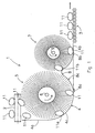
Fig. 1 shows a section of a sorting and packaging device having a preferred embodiment of a conveyor device in accordance with a first aspect of the invention, and -
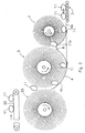
Fig. 2 shows another embodiment of a conveyor device in accordance with the first aspect of the invention. - In
Fig. 1 , reference numeral 1 denotes a preferred embodiment of the conveyor device. In the sorting and packaging device, the conveyor device 1 is positioned between afeed conveyor 2 and a discharge conveyor 3. In the example shown,feed conveyor 2 is located at a higher level than the discharge conveyor 3. The conveying direction of thefeed conveyor 2 is in this example substantially perpendicular to the plane of the drawing and transverse with respect to the conveying direction of the discharge conveyor 3. - The conveying device 1 has a
support track 4 which extends substantially from thefeed conveyor 2 to the discharge conveyor 3. At thefeed conveyor end 4a, thesupport track 4 extends substantially vertically downwards and then merges via acurved section 4c into a substantiallyhorizontal section 4b which adjoins the discharge conveyor 3. Thissupport track 4, may, for example, be made from a flexible plastic. - Furthermore, the conveyor device 1 comprises a first substantially
cylindrical brush 5 which is fixed to a rotation shaft 6. Thefirst brush 5 has substantially radially bristles which serve to engage on products, in this example eggs, which are located on thesupport track 4. Furthermore, the eggs are completely or partially held between the bristles, and the bristles are responsible for holding successive eggs at a distance from one another. The bristles therefore serve as a type of buffer. - A substantially cylindrical
second brush 7 is arranged downstream of thefirst brush 5, as seen in the conveying direction. The second brush is fixed to a rotation shaft 9 and in this embodiment has a smaller diameter than thefirst brush 5. Thesecond brush 7 has substantially radial bristles which have the same function as those of thefirst brush 5. Thesecond brush 7, in operation, rotates in the same direction as thefirst brush 5. - It should be noted that within the scope of the invention it is also possible to use other engagement members instead of brushes, in which case the engagement member is designed to be flexible or elastic at the circumference, so that the eggs or other products are not damaged. This could be achieved, for example, by designing the engagement members as rollers made from a soft graded foam or another suitable material.
- The
support track 4 is provided with an elevatedportion 8, which is located approximately at the level of an imaginary contact plane between the bristles of thefirst brush 2 and thesecond brush 7. The elevated portion is preferably produced from a strip of a flexible material, for example, a plastic, whoseedges support track 4. This fixing may be effected, for example, by theedges support track 4. Fixing may also be effected by gluing, riveting or any other suitable fixing method. Theedges intervening part 8c of the strip is, as it were, folded and therefore bulges upwards with respect to thesupport track 4. The flexibility of the strip of material provides theelevated portion 8 with the ability to yield to a certain extent when an egg is being guided over it by thebristles portion 8 prevents an egg from becoming stuck and breaking between thebrushes elevated portion 8. It is also possible for the strip to be arranged on the underside of thesupport track 4 if the latter is made from a flexible material. In that case, an upward bulge in the strip leads to an upward bulge in the track material. Thesupport track 4 may also be made from a flexible material, and at the location of the elevatedportion 8 may be secured to a base in such a manner that the material of thesupport track 4 bulges upwards. It is also possible for the elevated portion in thesupport track 4 to be formed in other ways. - In operation,
eggs 11 are supplied by thefeed conveyor 2. They may be supplied, for example, in two rows, as shown in the figure, although it is also possible for the eggs to be supplied randomly. The eggs lie at a certain distance from one another. At the end of theconveyor 2, theeggs 11 from the right-hand row (as seen in the drawing) of the conveyor, drop on to thefirst brush 5. Theeggs 11 in the left-hand row drop on to the bristles and thesupport track 4, are guided further downwards with support from thesupport track 4 by thebrush 5, as illustrated for theegg 11a. - The
eggs 11 which have been engaged on by thefirst brush 5, are carried along by the bristles and as a result acquire a substantially constant velocity, which is determined by the rotational speed of thebrush 5, along thesupport track 4. The eggs are guided along by thefirst brush 5 up to the highest point of the elevatedportion 8. At the highest point of the elevatedportion 8, theeggs 11 roll towards the downward side of the elevatedportion 8, and immediately after the highest point are engaged on by the bristles of thesecond brush 7 as indicated foregg 11b. If thesecond brush 7 is rotating at the same rotational speed as thefirst brush 5, theeggs 11 are decelerated by the smaller diameter of thesecond brush 7. As a result, the eggs are moved to a shorter distance from one another, so that the row ofeggs 11 is closed up. In an embodiment with brushes of identical dimensions or with brushes in which the first brush has a smaller diameter than the second brush (not shown), this closing-up effect can be achieved by virtue of the second brush rotating at a lower rotational speed than the first brush. - The
eggs 11 are then released to the discharge conveyor 3 at a distance from one another and velocity determined by the size and rotational speed of thesecond brush 7. -
Fig. 2 shows another convevor device according to the invention. - In this embodiment, the
eggs 11 are supplied by aconveyor belt 22. At the end 22a of theconveyor belt 22, the eggs drop downwards and are collected by thebrushes support track 4 is positioned between thebrushes eggs 11 are collected when they are carried downwards by thebrushes EP 0 098 734 . The remainder of the conveyor device corresponds to the conveyor device shown inFig. 1 , and corresponding components are denoted by identical reference numerals. - The embodiments shown in
Figs. 1 and2 are based on the common idea of the space which is always present as a result of the roundness of thefirst brush 5 and thesecond brush 7, arranged downstream of it in the conveying direction, being partially filled, such that the products are engaged on by one of the brushes over the longest possible path, with the result that the movement of the products is as fully controlled as possible. This space is partially filled by theelevated portion 8. - Furthermore, the support track may be designed as a stationary trough along which the products roll or slide (cf.
Figs. 1 and2 ). However, within the scope of the invention it is also possible for the support track to be in part of movable design, for example as a conveyor belt for actively advancing the products.
Claims (4)
- Conveyor device (1) for conveying substantially round but not completely spherical products (11), such as for example eggs (11), comprising a support track (4), along which the products (11) can move in a conveying direction during use, and a first, substantially cylindrical engagement member (5), which extends transversely over the support track (4) which respect to the conveying direction and which is flexible at least at its circumference, in order to engage on the products (11) on the support track without damaging them, and can rotate about its axial axis in order to advance the products (11) along the support track (4), wherein the support track (4), downstream of the first engagement member (5) as seen in the conveying direction, has an elevated portion (8) which is located at a distance from the first engagement member (5) which is such that the latter engages on the products (11) on the upward part of the elevated portion (8), characterized in that
downstream of the first engagement member (5), as seen in the conveying direction, there is arranged a second substantially cylindrical engagement member (7), which extends transversely across the support track (4) with respect to the conveying direction and which is flexible at least at the circumference, in order to engage on the products (11) on the support track without damaging them, and can rotate about its axial axis in the same direction as the first engagement member (6) in order to advance the products (11), along the support track (4), which second engagement member (7) is rotatable in the same direction as the first engagement member (5),
wherein the second engagement member (7), as seen in the conveying direction, is located at a distance downstream of the elevated portion (8) which is such that the second engagement member (7), engages on the products (11) on the downward section of the elevated portion (8). - Conveyor device according to claim 1, in which the elevated portion (8) is designed to be able to yield with the products (11).
- Conveyor device according to one of the preceding claims, in which the elevated portion (8) is formed from a strip of flexible material, of which a front end (8a) and a rear end (8b) are fixed at a distance from one another which is such that the material between them bulges upwards.
- Conveyor device according to one of claims 1-3, in which the first engagement member (5) is designed to have a greater circumferential velocity than the second engagement member (7) during use.
Applications Claiming Priority (2)
| Application Number | Priority Date | Filing Date | Title |
|---|---|---|---|
| NL1024299A NL1024299C2 (en) | 2003-09-15 | 2003-09-15 | Transport device. |
| PCT/NL2004/000630 WO2005026022A1 (en) | 2003-09-15 | 2004-09-13 | Conveyor and sorting and packaging device with such a conveyor |
Publications (3)
| Publication Number | Publication Date |
|---|---|
| EP1663821A1 EP1663821A1 (en) | 2006-06-07 |
| EP1663821B1 true EP1663821B1 (en) | 2009-03-18 |
| EP1663821B8 EP1663821B8 (en) | 2009-08-12 |
Family
ID=34309605
Family Applications (1)
| Application Number | Title | Priority Date | Filing Date |
|---|---|---|---|
| EP04774935A Expired - Lifetime EP1663821B8 (en) | 2003-09-15 | 2004-09-13 | Conveyor |
Country Status (7)
| Country | Link |
|---|---|
| US (1) | US7428961B2 (en) |
| EP (1) | EP1663821B8 (en) |
| JP (1) | JP4777890B2 (en) |
| AT (1) | ATE425931T1 (en) |
| DE (1) | DE602004020078D1 (en) |
| NL (1) | NL1024299C2 (en) |
| WO (1) | WO2005026022A1 (en) |
Families Citing this family (9)
| Publication number | Priority date | Publication date | Assignee | Title |
|---|---|---|---|---|
| EP2035306B1 (en) * | 2006-06-16 | 2011-07-13 | SACMI Cooperativa Meccanici Imola Società Cooperativa | Conveyor |
| US9565925B2 (en) * | 2009-06-17 | 2017-02-14 | Felton, Inc. | Flexible strip brush, flexible belt brush, and method for manufacturing the same |
| US8997446B2 (en) * | 2011-10-17 | 2015-04-07 | Dbr Conveyor Concepts, Llc | Pneumatic fruit decelerator body |
| DE102012204344B4 (en) * | 2012-03-19 | 2016-01-21 | Wafios Ag | forming machine |
| CH711547A1 (en) * | 2015-09-17 | 2017-03-31 | Wrh Walter Reist Holding Ag | Collecting device for a conveyor. |
| WO2017065610A1 (en) * | 2015-10-15 | 2017-04-20 | Moba Group B.V. | Apparatus for receiving and transporting a stream of eggs |
| CN208897461U (en) * | 2016-12-21 | 2019-05-24 | 利乐拉瓦尔集团及财务有限公司 | Packaging positioning device and filling machine containing the same |
| JP7678305B2 (en) * | 2021-08-06 | 2025-05-16 | シブヤ精機株式会社 | Item sorting device |
| NL2032104B1 (en) * | 2022-06-09 | 2023-12-18 | Burg Machf B V | Infeed apparatus and method of controlling infeed apparatus |
Family Cites Families (12)
| Publication number | Priority date | Publication date | Assignee | Title |
|---|---|---|---|---|
| USRE26003E (en) * | 1966-04-26 | Bowling ball elevator and return mechanisms | ||
| GB297230A (en) * | 1927-10-15 | 1928-09-20 | Reginald Brooks King | Egg washing machine |
| US3272309A (en) * | 1964-09-01 | 1966-09-13 | Barker Poultry Equipment Compa | Egg handling apparatus |
| US3613868A (en) * | 1970-08-05 | 1971-10-19 | Int Harvester Co | Conveyor wheel |
| IT1013761B (en) * | 1974-06-11 | 1977-03-30 | Valli Roberto | DEVICE FOR VERICALLY TRANSFER OF EGGS FOR PLANTS OF BATTERIES WITH MULTIPLE FLOORS FOR BREEDING SAYS IN ORDER TO FEEL THE CONVEYANCE AND COLLECTION OF THEM IN A SINGLE POSITION |
| US3953960A (en) * | 1974-08-09 | 1976-05-04 | Craven William E | Fruit picking apparatus |
| US4273649A (en) * | 1978-11-24 | 1981-06-16 | Leverett William H | Apparatus and process for weighing articles successively |
| US4519494A (en) * | 1982-07-01 | 1985-05-28 | Diamond Automations, Inc. | Egg handling system |
| US4597491A (en) * | 1984-04-05 | 1986-07-01 | Gerber Products Company | Truck loading apparatus and method |
| FR2596027B1 (en) * | 1986-03-21 | 1992-05-22 | Smcm | SYSTEM FOR TRANSFERRING FRAGILE OBJECTS, SUCH AS ESPECIALLY FRUIT, FROM A CONVEYOR TO A CONVEYOR |
| US5167317A (en) * | 1991-06-05 | 1992-12-01 | Fps Food Processing Systems B.V. | Apparatus for and method of transferring articles such as eggs |
| US6109421A (en) * | 1998-06-19 | 2000-08-29 | Magnuson Corporation | Corn transfer and alignment apparatus |
-
2003
- 2003-09-15 NL NL1024299A patent/NL1024299C2/en not_active IP Right Cessation
-
2004
- 2004-09-13 JP JP2006526844A patent/JP4777890B2/en not_active Expired - Fee Related
- 2004-09-13 US US10/571,665 patent/US7428961B2/en not_active Expired - Fee Related
- 2004-09-13 DE DE602004020078T patent/DE602004020078D1/en not_active Expired - Fee Related
- 2004-09-13 AT AT04774935T patent/ATE425931T1/en not_active IP Right Cessation
- 2004-09-13 WO PCT/NL2004/000630 patent/WO2005026022A1/en not_active Ceased
- 2004-09-13 EP EP04774935A patent/EP1663821B8/en not_active Expired - Lifetime
Also Published As
| Publication number | Publication date |
|---|---|
| US20070131521A1 (en) | 2007-06-14 |
| WO2005026022A1 (en) | 2005-03-24 |
| WO2005026022A9 (en) | 2007-04-12 |
| ATE425931T1 (en) | 2009-04-15 |
| JP4777890B2 (en) | 2011-09-21 |
| DE602004020078D1 (en) | 2009-04-30 |
| EP1663821A1 (en) | 2006-06-07 |
| JP2007505803A (en) | 2007-03-15 |
| EP1663821B8 (en) | 2009-08-12 |
| US7428961B2 (en) | 2008-09-30 |
| NL1024299C2 (en) | 2005-03-16 |
Similar Documents
| Publication | Publication Date | Title |
|---|---|---|
| US5167317A (en) | Apparatus for and method of transferring articles such as eggs | |
| US3499519A (en) | Fruit feeding apparatus | |
| US7428961B2 (en) | Conveyor device | |
| EP2196412B1 (en) | Apparatus and method for orienting objects | |
| US5086909A (en) | Gentle handling of fruit during weight sizing and other operations | |
| CN108991568B (en) | Garlic root hair excision system | |
| CA1167729A (en) | Apparatus and method for separating the pulp from the skin of fruit such as tomatoes | |
| US6415902B1 (en) | Orientation mechanism | |
| US2403516A (en) | Fruit halving and pitting machinery | |
| CN105410962A (en) | Mushroom drying device | |
| JPH0266006A (en) | Device for capturing and moving vertical supply article | |
| US5954184A (en) | Apparatus and method for feeding, presenting and/or orienting parts | |
| EP0345036A1 (en) | Off-loading conveying system | |
| US5215179A (en) | Off-loading conveying system | |
| US3669240A (en) | Method and apparatus for orienting articles | |
| KR101921185B1 (en) | Tray automatic feeder in a fruit sorting apparatus | |
| US9963300B2 (en) | Collecting device for a conveyor | |
| CN108771273B (en) | Method for cutting fibrous roots of garlic | |
| CN108968120B (en) | Garlic processing system | |
| US3015378A (en) | Orientation apparatus for articles to be wrapped | |
| KR101303836B1 (en) | Sorting apparatus using centrifugal force | |
| CN219728639U (en) | Fruit feeding and discharging equipment | |
| US6644905B1 (en) | Bin filler for fruit crops | |
| CN118287396B (en) | Bad fruit removing device | |
| KR102440996B1 (en) | Bulb peeling and sorting device |
Legal Events
| Date | Code | Title | Description |
|---|---|---|---|
| PUAI | Public reference made under article 153(3) epc to a published international application that has entered the european phase |
Free format text: ORIGINAL CODE: 0009012 |
|
| 17P | Request for examination filed |
Effective date: 20060221 |
|
| AK | Designated contracting states |
Kind code of ref document: A1 Designated state(s): AT BE BG CH CY CZ DE DK EE ES FI FR GB GR HU IE IT LI LU MC NL PL PT RO SE SI SK TR |
|
| DAX | Request for extension of the european patent (deleted) | ||
| 17Q | First examination report despatched |
Effective date: 20061222 |
|
| GRAP | Despatch of communication of intention to grant a patent |
Free format text: ORIGINAL CODE: EPIDOSNIGR1 |
|
| RTI1 | Title (correction) |
Free format text: CONVEYOR |
|
| GRAS | Grant fee paid |
Free format text: ORIGINAL CODE: EPIDOSNIGR3 |
|
| GRAA | (expected) grant |
Free format text: ORIGINAL CODE: 0009210 |
|
| AK | Designated contracting states |
Kind code of ref document: B1 Designated state(s): AT BE BG CH CY CZ DE DK EE ES FI FR GB GR HU IE IT LI LU MC NL PL PT RO SE SI SK TR |
|
| REG | Reference to a national code |
Ref country code: GB Ref legal event code: FG4D |
|
| REG | Reference to a national code |
Ref country code: CH Ref legal event code: EP |
|
| REG | Reference to a national code |
Ref country code: IE Ref legal event code: FG4D |
|
| REF | Corresponds to: |
Ref document number: 602004020078 Country of ref document: DE Date of ref document: 20090430 Kind code of ref document: P |
|
| RAP2 | Party data changed (patent owner data changed or rights of a patent transferred) |
Owner name: STAALKAT INTERNATIONAL B.V. |
|
| PG25 | Lapsed in a contracting state [announced via postgrant information from national office to epo] |
Ref country code: FI Free format text: LAPSE BECAUSE OF FAILURE TO SUBMIT A TRANSLATION OF THE DESCRIPTION OR TO PAY THE FEE WITHIN THE PRESCRIBED TIME-LIMIT Effective date: 20090318 Ref country code: SI Free format text: LAPSE BECAUSE OF FAILURE TO SUBMIT A TRANSLATION OF THE DESCRIPTION OR TO PAY THE FEE WITHIN THE PRESCRIBED TIME-LIMIT Effective date: 20090318 |
|
| NLT2 | Nl: modifications (of names), taken from the european patent patent bulletin |
Owner name: STAALKAT INTERNATIONAL B.V. Effective date: 20090603 |
|
| NLXE | Nl: other communications concerning ep-patents (part 3 heading xe) |
Free format text: PAT. BUL. 06/2009, PAGE 842: CORR.: STAALKAT INTERNATIONAL B.V. |
|
| PG25 | Lapsed in a contracting state [announced via postgrant information from national office to epo] |
Ref country code: AT Free format text: LAPSE BECAUSE OF FAILURE TO SUBMIT A TRANSLATION OF THE DESCRIPTION OR TO PAY THE FEE WITHIN THE PRESCRIBED TIME-LIMIT Effective date: 20090318 Ref country code: SE Free format text: LAPSE BECAUSE OF FAILURE TO SUBMIT A TRANSLATION OF THE DESCRIPTION OR TO PAY THE FEE WITHIN THE PRESCRIBED TIME-LIMIT Effective date: 20090618 Ref country code: PL Free format text: LAPSE BECAUSE OF FAILURE TO SUBMIT A TRANSLATION OF THE DESCRIPTION OR TO PAY THE FEE WITHIN THE PRESCRIBED TIME-LIMIT Effective date: 20090318 |
|
| PG25 | Lapsed in a contracting state [announced via postgrant information from national office to epo] |
Ref country code: BE Free format text: LAPSE BECAUSE OF FAILURE TO SUBMIT A TRANSLATION OF THE DESCRIPTION OR TO PAY THE FEE WITHIN THE PRESCRIBED TIME-LIMIT Effective date: 20090318 |
|
| PG25 | Lapsed in a contracting state [announced via postgrant information from national office to epo] |
Ref country code: EE Free format text: LAPSE BECAUSE OF FAILURE TO SUBMIT A TRANSLATION OF THE DESCRIPTION OR TO PAY THE FEE WITHIN THE PRESCRIBED TIME-LIMIT Effective date: 20090318 Ref country code: ES Free format text: LAPSE BECAUSE OF FAILURE TO SUBMIT A TRANSLATION OF THE DESCRIPTION OR TO PAY THE FEE WITHIN THE PRESCRIBED TIME-LIMIT Effective date: 20090629 Ref country code: CZ Free format text: LAPSE BECAUSE OF FAILURE TO SUBMIT A TRANSLATION OF THE DESCRIPTION OR TO PAY THE FEE WITHIN THE PRESCRIBED TIME-LIMIT Effective date: 20090318 Ref country code: PT Free format text: LAPSE BECAUSE OF FAILURE TO SUBMIT A TRANSLATION OF THE DESCRIPTION OR TO PAY THE FEE WITHIN THE PRESCRIBED TIME-LIMIT Effective date: 20090826 |
|
| PG25 | Lapsed in a contracting state [announced via postgrant information from national office to epo] |
Ref country code: SK Free format text: LAPSE BECAUSE OF FAILURE TO SUBMIT A TRANSLATION OF THE DESCRIPTION OR TO PAY THE FEE WITHIN THE PRESCRIBED TIME-LIMIT Effective date: 20090318 Ref country code: RO Free format text: LAPSE BECAUSE OF FAILURE TO SUBMIT A TRANSLATION OF THE DESCRIPTION OR TO PAY THE FEE WITHIN THE PRESCRIBED TIME-LIMIT Effective date: 20090318 |
|
| PLBE | No opposition filed within time limit |
Free format text: ORIGINAL CODE: 0009261 |
|
| STAA | Information on the status of an ep patent application or granted ep patent |
Free format text: STATUS: NO OPPOSITION FILED WITHIN TIME LIMIT |
|
| PG25 | Lapsed in a contracting state [announced via postgrant information from national office to epo] |
Ref country code: BG Free format text: LAPSE BECAUSE OF FAILURE TO SUBMIT A TRANSLATION OF THE DESCRIPTION OR TO PAY THE FEE WITHIN THE PRESCRIBED TIME-LIMIT Effective date: 20090618 Ref country code: DK Free format text: LAPSE BECAUSE OF FAILURE TO SUBMIT A TRANSLATION OF THE DESCRIPTION OR TO PAY THE FEE WITHIN THE PRESCRIBED TIME-LIMIT Effective date: 20090318 |
|
| 26N | No opposition filed |
Effective date: 20091221 |
|
| PG25 | Lapsed in a contracting state [announced via postgrant information from national office to epo] |
Ref country code: MC Free format text: LAPSE BECAUSE OF NON-PAYMENT OF DUE FEES Effective date: 20090930 |
|
| REG | Reference to a national code |
Ref country code: CH Ref legal event code: PL |
|
| GBPC | Gb: european patent ceased through non-payment of renewal fee |
Effective date: 20090913 |
|
| REG | Reference to a national code |
Ref country code: FR Ref legal event code: ST Effective date: 20100531 |
|
| PG25 | Lapsed in a contracting state [announced via postgrant information from national office to epo] |
Ref country code: DE Free format text: LAPSE BECAUSE OF NON-PAYMENT OF DUE FEES Effective date: 20100401 Ref country code: FR Free format text: LAPSE BECAUSE OF NON-PAYMENT OF DUE FEES Effective date: 20090930 Ref country code: IE Free format text: LAPSE BECAUSE OF NON-PAYMENT OF DUE FEES Effective date: 20090913 |
|
| PG25 | Lapsed in a contracting state [announced via postgrant information from national office to epo] |
Ref country code: LI Free format text: LAPSE BECAUSE OF NON-PAYMENT OF DUE FEES Effective date: 20090930 Ref country code: CH Free format text: LAPSE BECAUSE OF NON-PAYMENT OF DUE FEES Effective date: 20090930 Ref country code: GR Free format text: LAPSE BECAUSE OF FAILURE TO SUBMIT A TRANSLATION OF THE DESCRIPTION OR TO PAY THE FEE WITHIN THE PRESCRIBED TIME-LIMIT Effective date: 20090619 |
|
| PG25 | Lapsed in a contracting state [announced via postgrant information from national office to epo] |
Ref country code: GB Free format text: LAPSE BECAUSE OF NON-PAYMENT OF DUE FEES Effective date: 20090913 |
|
| PG25 | Lapsed in a contracting state [announced via postgrant information from national office to epo] |
Ref country code: LU Free format text: LAPSE BECAUSE OF NON-PAYMENT OF DUE FEES Effective date: 20090913 |
|
| PG25 | Lapsed in a contracting state [announced via postgrant information from national office to epo] |
Ref country code: HU Free format text: LAPSE BECAUSE OF FAILURE TO SUBMIT A TRANSLATION OF THE DESCRIPTION OR TO PAY THE FEE WITHIN THE PRESCRIBED TIME-LIMIT Effective date: 20090919 |
|
| PG25 | Lapsed in a contracting state [announced via postgrant information from national office to epo] |
Ref country code: TR Free format text: LAPSE BECAUSE OF FAILURE TO SUBMIT A TRANSLATION OF THE DESCRIPTION OR TO PAY THE FEE WITHIN THE PRESCRIBED TIME-LIMIT Effective date: 20090318 |
|
| PG25 | Lapsed in a contracting state [announced via postgrant information from national office to epo] |
Ref country code: CY Free format text: LAPSE BECAUSE OF FAILURE TO SUBMIT A TRANSLATION OF THE DESCRIPTION OR TO PAY THE FEE WITHIN THE PRESCRIBED TIME-LIMIT Effective date: 20090318 |
|
| PGFP | Annual fee paid to national office [announced via postgrant information from national office to epo] |
Ref country code: IT Payment date: 20210929 Year of fee payment: 18 Ref country code: NL Payment date: 20210923 Year of fee payment: 18 |
|
| REG | Reference to a national code |
Ref country code: NL Ref legal event code: MM Effective date: 20221001 |
|
| PG25 | Lapsed in a contracting state [announced via postgrant information from national office to epo] |
Ref country code: NL Free format text: LAPSE BECAUSE OF NON-PAYMENT OF DUE FEES Effective date: 20221001 |
|
| PG25 | Lapsed in a contracting state [announced via postgrant information from national office to epo] |
Ref country code: IT Free format text: LAPSE BECAUSE OF NON-PAYMENT OF DUE FEES Effective date: 20220913 |