EP1663729B1 - Insassenschutzsystem für ein fahrzeug - Google Patents
Insassenschutzsystem für ein fahrzeug Download PDFInfo
- Publication number
- EP1663729B1 EP1663729B1 EP04741419A EP04741419A EP1663729B1 EP 1663729 B1 EP1663729 B1 EP 1663729B1 EP 04741419 A EP04741419 A EP 04741419A EP 04741419 A EP04741419 A EP 04741419A EP 1663729 B1 EP1663729 B1 EP 1663729B1
- Authority
- EP
- European Patent Office
- Prior art keywords
- drive
- protection system
- passenger protection
- passenger
- movement
- Prior art date
- Legal status (The legal status is an assumption and is not a legal conclusion. Google has not performed a legal analysis and makes no representation as to the accuracy of the status listed.)
- Expired - Lifetime
Links
- 230000007246 mechanism Effects 0.000 claims abstract description 22
- 230000001960 triggered effect Effects 0.000 claims abstract description 5
- 239000006096 absorbing agent Substances 0.000 claims description 8
- 230000000452 restraining effect Effects 0.000 claims description 8
- 239000003380 propellant Substances 0.000 claims description 4
- 238000001514 detection method Methods 0.000 claims description 3
- 230000007935 neutral effect Effects 0.000 claims 3
- 230000001131 transforming effect Effects 0.000 abstract 1
- 210000003127 knee Anatomy 0.000 description 6
- 238000010521 absorption reaction Methods 0.000 description 4
- 230000000694 effects Effects 0.000 description 3
- 230000001681 protective effect Effects 0.000 description 3
- 230000005540 biological transmission Effects 0.000 description 2
- 230000000903 blocking effect Effects 0.000 description 2
- 238000006243 chemical reaction Methods 0.000 description 2
- 230000006872 improvement Effects 0.000 description 2
- 238000009434 installation Methods 0.000 description 2
- 238000000034 method Methods 0.000 description 2
- 230000008569 process Effects 0.000 description 2
- 230000002441 reversible effect Effects 0.000 description 2
- 208000016593 Knee injury Diseases 0.000 description 1
- 230000009471 action Effects 0.000 description 1
- 238000000418 atomic force spectrum Methods 0.000 description 1
- 239000011324 bead Substances 0.000 description 1
- 230000006835 compression Effects 0.000 description 1
- 238000007906 compression Methods 0.000 description 1
- 230000001419 dependent effect Effects 0.000 description 1
- 238000011161 development Methods 0.000 description 1
- 230000018109 developmental process Effects 0.000 description 1
- 238000006073 displacement reaction Methods 0.000 description 1
- 231100001261 hazardous Toxicity 0.000 description 1
- 230000002427 irreversible effect Effects 0.000 description 1
- 230000000670 limiting effect Effects 0.000 description 1
- 230000014759 maintenance of location Effects 0.000 description 1
- 230000004044 response Effects 0.000 description 1
- 230000035939 shock Effects 0.000 description 1
- 239000000725 suspension Substances 0.000 description 1
Images

Classifications
-
- B—PERFORMING OPERATIONS; TRANSPORTING
- B60—VEHICLES IN GENERAL
- B60R—VEHICLES, VEHICLE FITTINGS, OR VEHICLE PARTS, NOT OTHERWISE PROVIDED FOR
- B60R21/00—Arrangements or fittings on vehicles for protecting or preventing injuries to occupants or pedestrians in case of accidents or other traffic risks
- B60R21/02—Occupant safety arrangements or fittings, e.g. crash pads
-
- B—PERFORMING OPERATIONS; TRANSPORTING
- B60—VEHICLES IN GENERAL
- B60R—VEHICLES, VEHICLE FITTINGS, OR VEHICLE PARTS, NOT OTHERWISE PROVIDED FOR
- B60R21/00—Arrangements or fittings on vehicles for protecting or preventing injuries to occupants or pedestrians in case of accidents or other traffic risks
- B60R2021/003—Arrangements or fittings on vehicles for protecting or preventing injuries to occupants or pedestrians in case of accidents or other traffic risks characterised by occupant or pedestian
- B60R2021/0039—Body parts of the occupant or pedestrian affected by the accident
- B60R2021/0051—Knees
-
- B—PERFORMING OPERATIONS; TRANSPORTING
- B60—VEHICLES IN GENERAL
- B60R—VEHICLES, VEHICLE FITTINGS, OR VEHICLE PARTS, NOT OTHERWISE PROVIDED FOR
- B60R21/00—Arrangements or fittings on vehicles for protecting or preventing injuries to occupants or pedestrians in case of accidents or other traffic risks
- B60R21/02—Occupant safety arrangements or fittings, e.g. crash pads
- B60R2021/0206—Self-supporting restraint systems, e.g. restraining arms, plates or the like
- B60R2021/024—Self-supporting restraint systems, e.g. restraining arms, plates or the like mounted on dash-board
-
- B—PERFORMING OPERATIONS; TRANSPORTING
- B60—VEHICLES IN GENERAL
- B60R—VEHICLES, VEHICLE FITTINGS, OR VEHICLE PARTS, NOT OTHERWISE PROVIDED FOR
- B60R21/00—Arrangements or fittings on vehicles for protecting or preventing injuries to occupants or pedestrians in case of accidents or other traffic risks
- B60R21/02—Occupant safety arrangements or fittings, e.g. crash pads
- B60R2021/0206—Self-supporting restraint systems, e.g. restraining arms, plates or the like
- B60R2021/0246—Self-supporting restraint systems, e.g. restraining arms, plates or the like mounted on side walls
Definitions
- the invention relates to an occupant protection system for a vehicle with a preferably formed as a baffle plate, the vehicle occupant facing baffle surface having retaining body and a triggerable in a dangerous situation extending device for a translational extension movement of the retaining body between a rest position and a displaced to the vehicle occupant extension position.
- a safety device of this type is known in which a pad plate is mounted at knee height in the front end of the vehicle and by means of a spring drive to the knees of the passenger is displaced.
- the spring drive has a biased at rest, releasable against the direction of travel leaf spring.
- the pad plate is attached to the back of two cylindrical, aligned in the vehicle longitudinal direction slideways.
- a parallel to the sliding guides push rod for power transmission from the leaf spring is provided on the cushion plate.
- the disadvantage here is especially the high space requirement, which results from the orientation of the guide and the push rod in the X direction of the vehicle.
- the protective effect due to the low extension speed and energy absorption of the cushion plate is rather limited.
- the object of the invention is to avoid the disadvantages which have arisen in the prior art and to improve a system of the type specified at the beginning in such a way that a reliable high safety function is ensured in the case of compact installation space dimensions.
- the invention is based on the idea of creating an actuator arrangement transversely to the actual direction of movement of the retaining element. Accordingly, the invention proposes that the extension device has a transverse drive for a drive movement transversely to the extension direction and a deflection mechanism for deflecting the drive movement in the extension movement. In this way, a very compact, limited in depth space can be maintained, which in particular accommodates the cramped installation conditions in the front end of the vehicle. By aligning the drive in the vehicle transverse direction is sufficient space available to achieve an effective and fast protection.
- the deflection mechanism has at least one two-armed pivoting lever which is pivotable about a rotation axis perpendicular to the drive and extension movement and which is coupled at the end via hinge connections to the retaining body and the transverse drive. Due to the additional use of a rotational degree of freedom, the kinematics can be optimized with comparatively simple means.
- a further improvement also with regard to a compact arrangement is achieved in that the pivot lever is angled as a two-armed angle lever in the region of the axis of rotation.
- the pivot lever is connected to a retraction-side lever arm via a sliding joint with the retaining body and is preferably articulated on a drive-side lever arm on a guided in the drive direction drive rod in a guide slot.
- the deflection mechanism two with respect to a vertical Having center line extending to the drive direction has mirror-symmetrically arranged lever linkage.
- a particularly effective actuator can be achieved in that the transverse drive has an orthogonal to the extension direction oriented drive cylinder.
- a further improvement provides that at least one in the rest state biased, coupled to the deflection mechanism drive spring is mounted in the drive cylinder.
- the drive cylinder can be acted upon by compressed gas via a pyrotechnic propellant charge and has a piston rod coupled to the deflection mechanism.
- the drive cylinder can optionally be actuated mechanically and / or pyrotechnically-pneumatically.
- the extension device has an effective in different extended positions locking mechanism, in particular a one-sided Zahnrichtgesperre for securing the reverse drive of the transverse drive in the extension movement.
- a shock absorber which can be actuated by reversing the direction of travel of the extension movement via the deflection mechanism and which is deformable under energy absorption is provided.
- the deflection mechanism thus has a double function for setting up the retaining body and for transmitting power under load in the opposite direction.
- a particularly compact design provides that the crash cushion is aligned as a power transmission member of the transverse drive in the drive direction. It is advantageous if the crash cushion is formed by a telescopic tube, which is collapsible against a force and / or positive connection in the drive direction.
- the extension device by a accident detection device in particular a pre-crash sensor in a hazardous situation can be triggered preventively.
- the extension device has a reversing drive for returning the retaining body in the rest position.
- a further advantageous embodiment provides that the retaining body is arranged as a knee protection plate for a passenger in the area of the instrument panel of a motor vehicle and is advantageously also designed as a glove box cover.
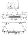
- the protection system 10 shown in the drawing serves to reduce knee injuries of a passenger in a danger or accident situation.
- the system 10 is installed on the passenger side at knee height in the area of the instrument panel 12 of the vehicle 14 and consists essentially of a retaining body formed as a baffle plate 16 and an extension device engaging in two superposed planes via separate actuator units 18 on the baffle plate for a translatory extension movement of the baffle plate 16 in a direction of extension 20 to the vehicle occupant.
- the actuator units 18 each have a transverse drive 20 for a linear drive movement perpendicular to the extension direction 21 and a deflection mechanism 22 for deflecting the drive movement into the extension movement.
- the transverse drive comprises a drive cylinder 24 oriented in the vehicle transverse direction orthogonal to the extension direction 21 and which operates mechanically and / or pyrotechnically in the various embodiments described below.
- a cylindrical helical tension spring 26 is mounted in the drive cylinder 24, which is biased in the rest position of the baffle plate 16 shown in FIG. At its spring ends, the tension coil spring 26 is connected to tie rods 28 of the deflection mechanism 22, which are guided in the pulling axis 29 through the end faces of the drive cylinder 24.
- the deflection mechanism 22 has two pivoting levers 30 which, as two-armed angle levers in the region of their kneeling position, are fixed to the vehicle over a vertical axis for extension and drive movement Rotary axis 32 are pivotable.
- the pivot lever 30 are connected at their drive-side lever arm via a respective joint connection 34 with the tie rods 28 and at its extension lever arm via a respective thrust articulation 36 with the baffle plate 16.
- a Zahnrichtgesperre 38 is provided on each tie rod 28, the locking piece 40 is unlocked via a triggering device 42.
- the spring-loaded locking piece 40 runs during the extension process over the opposite direction of the tensile direction inclined tooth flanks, while in the reverse direction, a positive locking over vertical counter flanks is achieved. In this way, a return blocking in each extended position is possible, in which a contact of the baffle plate 16 is achieved with the knees of the vehicle occupant. It is understood that the two mirror-symmetrically arranged lever linkage 28, 30 are operated synchronously in the same direction of action in order to achieve optimum deployment.
- the baffle plate 16 serves in the rest position as a panel for covering the extension device 18 and forms with its front side 44 a design-relevant surface of the vehicle interior. In use, the baffle plate 16 forms a contact elements for supporting the vehicle occupant. In this function, a first energy absorbing effect can be achieved by a foamed resilient layer, not shown.
- impact absorbers 46 are provided for additional absorption of kinetic energy of the vehicle occupant, which are actuated during a return movement under load by the deflection mechanism 22.
- the impact absorbers 46 are formed by a stuffer tube portion 48 at the rod end of the piston rods 28, which is telescopically movable against a positive connection (bead 50) when a given Axialkraftlomis is exceeded.
- a positive connection be exceeded.
- the restraining force should initially rise steeply over the path, and then remain constant above a certain level of force.
- the integral of the force curve the amount of the work done deformation work can be maximized while limiting the force level.
- the rod-side cylinder chamber can be acted upon by a pyrotechnically operating gas generator 54 with propellant, so as to allow a sudden unfolding or positioning on the guided in the drive cylinder 24 piston 52 of the piston rods 28 each have the biasing force of a rod side, cylindrical helical compression spring ,
- the return protection takes place via the Zahnrichtgesperre 38, which is formed in this embodiment by a rack which protrudes on a piston 52 on the bottom side and dips through the other hollow piston into the hollow rod, wherein the spring-loaded locking piece 40 is carried along with the hollow piston.
- the drive-side hinge pin 34 of the pivot lever 30 is mounted in a guide slot 56, which gives an additional translational degree of freedom, as compensation for the arc height in the rotational movement of the pivot lever 30 relative to the Piston rod 28 is necessary.
- the restraint system described in the embodiment of FIGS. 4 and 5 can be used both for a slow, gentle unfolding as well as for a fast, time-critical deployment.
- the spring drive 26 is triggered preventively by a predictive pre-crash sensor of the trip unit 42. Due to the released spring forces push the piston 52, the piston rods 28 on both sides of the cylinder bottoms through and provide by means of the hinge pin 34, the pivot lever 30, wherein the rotational movement about the axis of rotation 32 by a translation of the sliding joints 36 in the baffle side backdrop 58 is again converted into a pure translational movement of the baffle plate 16.
- the baffle plate 16 is thereby moved relatively slowly and thus uncritically for the person to be protected in the extended position shown in Fig. 5.
- a propellant gas is generated by ignition of the gas generator 54 by pyrotechnic means, with which the rod-side cylinder chambers are acted upon.
- the gas pressure is so high that the piston 52 are accelerated in a few milliseconds to its final position and the baffle plate 16 is deployed abruptly.
- the protective system described can advantageously be used at various points in the motor vehicle, for example also in the area of a door trim or a B pillar as side impact protection.
Landscapes
- Engineering & Computer Science (AREA)
- Mechanical Engineering (AREA)
- Superstructure Of Vehicle (AREA)
- Automotive Seat Belt Assembly (AREA)
- Seats For Vehicles (AREA)
- Lock And Its Accessories (AREA)
- Emergency Alarm Devices (AREA)
Description
- Die Erfindung betrifft ein Insassenschutzsystem für ein Fahrzeug mit einem vorzugsweise als Prallplatte ausgebildeten, eine dem Fahrzeuginsassen zugewandte Prallfläche aufweisenden Rückhaltekörper und einer in einer Gefahrensituation auslösbaren Ausfahrvorrichtung für eine translatorische Ausfahrbewegung des Rückhaltekörpers zwischen einer Ruhestellung und einer zu dem Fahrzeuginsassen hin verlagerten Ausfahrstellung.
- Aus der DE-A-43 28 446 und der nächtliegenden DE 42 01 824 A ist eine Sicherheitseinrichtung dieser Art bekannt, bei der eine Polsterplatte in Kniehöhe in der Frontpartie des Fahrzeugs angebracht ist und mittels eines Federantriebs zu den Knien des Fahrgasts hin verschiebbar ist. Der Federantrieb weist eine im Ruhezustand vorgespannte, gegen die Fahrtrichtung auslösbare Blattfeder auf. Die Polsterplatte ist dabei rückseitig an zwei zylindrischen, in Fahrzeuglängsrichtung ausgerichteten Gleitführungen befestigt. Zusätzlich ist eine zu den Gleitführungen parallele Schubstange zur Kraftübertragung von der Blattfeder auf die Polsterplatte vorgesehen. Als nachteilig wird hierbei vor allem der hohe Bauraumbedarf angesehen, der sich durch die Ausrichtung der Führung und der Schubstange in X-Richtung des Fahrzeugs ergibt. Zudem ist bei diesem System die Schutzwirkung auf Grund der geringen Ausfahrgeschwindigkeit und Energieabsorption der Polsterplatte eher beschränkt.
- Ausgehend hiervon liegt der Erfindung die Aufgabe zugrunde, die im Stand der Technik aufgetretenen Nachteile zu vermeiden und ein System der eingangs angegebenen Art dahin zu verbessern, dass bei kompakten Bauraumabmaßen eine zuverlässige hohe Sicherheitsfunktion gewährleistet ist.
- Zur Lösung dieser Aufgabe wird die im Patentanspruch 1 angegebene Merkmalskombination vorgeschlagen. Vorteilhafte Ausgestaltungen und Weiterbildungen der Erfindung ergeben sich aus den abhängigen Ansprüchen.
- Die Erfindung geht von dem Gedanken aus, eine Aktuatoranordnung quer zur eigentlichen Bewegungsrichtung des Rückhalteelements zu schaffen. Dementsprechend wird erfindungsgemäß vorgeschlagen, dass die Ausfahrvorrichtung einen Querantrieb für eine Antriebsbewegung quer zur Ausfahrrichtung und einen Umlenkmechanismus zur Umlenkung der Antriebsbewegung in die Ausfahrbewegung aufweist. Auf diese Weise kann ein sehr kompakter, in der Tiefe begrenzter Bauraum eingehalten werden, was insbesondere den beengten Einbauverhältnissen in der Frontpartie des Fahrzeugs Rechnung trägt. Durch die Ausrichtung des Antriebs in Fahrzeugquerrichtung steht ausreichend Freiraum zu Verfügung, um eine effektive und schnelle Schutzwirkung zu erreichen.
- Vorteilhafterweise besitzt der Umlenkmechanismus mindestens einen um eine zur Antriebs- und Ausfahrbewegung senkrechte Drehachse schwenkbaren, zweiarmigen Schwenkhebel, welcher endseitig über Gelenkanschlüsse mit dem Rückhaltekörper und dem Querantrieb gekoppelt ist. Durch die zusätzliche Nutzung eines rotatorischen Freiheitsgrades kann die Kinematik mit vergleichsweise einfachen Mitteln optimiert werden. Eine weitere Verbesserung auch im Hinblick auf eine kompakte Anordnung wird dadurch erreicht, dass der Schwenkhebel als zweiarmiger Winkelhebel im Bereich der Drehachse abgewinkelt ist. Hierbei ist es günstig, wenn der Schwenkhebel an einem ausfahrseitigen Hebelarm über ein Schubgelenk mit dem Rückhaltekörper verbunden ist und an einem antriebseitigen Hebelarm an einer in Antriebsrichtung geführten Antriebsstange vorzugsweise in einer Führungskulisse angelenkt ist.
- Um das Einbringen von Quermomenten beim Aufprall einzuschränken, ist es vorteilhaft, wenn der Umlenkmechanismus zwei bezüglich einer senkrecht zur Antriebsrichtung verlaufenden Mittelebene spiegelsymmetrisch zueinander angeordnete Hebelgestänge aufweist.
- Eine besonders effektive Aktuatorik lässt sich dadurch erreichen, dass der Querantrieb einen orthogonal zur Ausfahrrichtung ausgerichteten Antriebszylinder aufweist. Eine weitere Verbesserung sieht vor, dass in dem Antriebszylinder mindestens eine im Ruhezustand vorgespannte, mit dem Umlenkmechanismus gekoppelte Antriebsfeder gelagert ist.
- Um eine besonders schnelle Reaktion in einer Unfallsituation zu ermöglichen, ist es von Vorteil, wenn der Antriebszylinder über eine pyrotechnische Treibladung mit Druckgas beaufschlagbar ist und eine mit dem Umlenkmechanismus gekoppelte Kolbenstange aufweist.
- Um entsprechend der jeweiligen Unfallsituation optimal reagieren zu können, sieht eine bevorzugte Ausführung vor, dass der Antriebszylinder wahlweise mechanisch und/oder pyrotechnisch-pneumatisch betätigbar ist.
- Für eine an unterschiedliche Positionen des Fahrzeuginsassen angepasste Rückhaltewirkung ist es günstig, wenn die Ausfahrvorrichtung ein in verschiedenen Ausfahrstellungen wirksames Gesperre, insbesondere ein einseitiges Zahnrichtgesperre zur Rücklaufsicherung des Querantriebs bei der Ausfahrbewegung aufweist.
- Um eine zusätzliche Schutzwirkung unter Aufnahme kinetischer Energie des Fahrgastes zu erreichen, ist ein unter Richtungsumkehr der Ausfahrbewegung über den Umlenkmechanismus betätigbarer, unter Energieabsorption verformbarer Aufpralldämpfer vorgesehen. Der Umlenkmechanismus besitzt somit eine Doppelfunktion zum Aufstellen des Rückhaltekörpers und zur Kraftübertragung unter Belastung in Gegenrichtung.
- Eine besonders kompakte Ausführung sieht vor, dass der Aufpralldämpfer als Kraftübertragungsglied des Querantriebs in Antriebsrichtung ausgerichtet ist. Hierbei ist es von Vorteil, wenn der Aufpralldämpfer durch ein Teleskoprohr gebildet ist, welches entgegen einer Kraft- und/oder Formschlussverbindung in Antriebsrichtung zusammenschiebbar ist.
- Für eine situationsgerechte Reaktion bei einer Unfallfrüherkennung ist es vorteilhaft, wenn die Ausfahrvorrichtung durch eine Unfallerfassungseinrichtung, insbesondere einen Pre-Crash-Sensor bei einer Gefährdungssituation präventiv auslösbar ist.
- Für den Fall, dass das System nicht irreversibel beansprucht wurde, ist es von Vorteil, wenn die Ausfahrvorrichtung einen Reversierantrieb zum Zurückfahren des Rückhaltekörpers in die Ruhestellung aufweist.
- Eine weitere vorteilhafte Ausführung sieht vor, dass der Rückhaltekörper als Knieschutzplatte für einen Beifahrer im Bereich der Instrumententafel eines Kraftfahrzeugs angeordnet ist und vorteilhafterweise zugleich als Handschuhkastenabdeckung ausgebildet ist.
- Im Folgenden wird die Erfindung anhand eines in der Zeichnung in schematischer Weise dargestellten Ausführungsbeispiels näher erläutert. Es zeigen
- Fig. 1
- eine aus einer Instrumententafel ausfahrbare Rückhalteeinrichtung als Knieschutzsystem für einen Fahrzeuginsassen in einem vereinfachten ausschnittsweisen Vertikalschnitt des Fahrzeugs;
- Fig. 2 und 3
- eine Ausfahrvorrichtung der Rückhalteeinrichtung in einem Horizontalschnitt in der Ruhestellung und in einer Ausfahrstellung; und
- Fig. 4 und 5
- eine weitere Ausführungsform einer Ausfahrvorrichtung in einer Fig. 2 und 3 entsprechenden Darstellung.
- Das in der Zeichnung dargestellte Schutzsystem 10 dient zur Minderung von Knieverletzungen eines Beifahrers in einer Gefahren- bzw. Unfallsituation. Das System 10 ist im Bereich der Instrumententafel 12 des Fahrzeugs 14 beifahrerseitig in Kniehöhe eingebaut und besteht im Wesentlichen aus einem als Prallplatte 16 ausgebildeten Rückhaltekörper und einer in zwei übereinander liegenden Ebenen über gesonderte Aktuatoreinheiten 18 rückseitig an der Prallplatte angreifenden Ausfahrvorrichtung für eine translatorische Ausfahrbewegung der Prallplatte 16 in eine Ausfahrrichtung 20 auf den Fahrzeuginsassen zu.
- Wie am besten aus Fig. 2 bis 5 ersichtlich, weisen die Aktuatoreinheiten 18 jeweils einen Querantrieb 20 für eine lineare Antriebsbewegung senkrecht zur Ausfahrrichtung 21 und einen Umlenkmechanismus 22 zur Umlenkung der Antriebsbewegung in die Ausfahrbewegung auf. Der Querantrieb umfasst einen in Fahrzeugquerrichtung orthogonal zur Ausfahrrichtung 21 ausgerichteten Antriebszylinder 24, der in den verschiedenen nachstehend beschriebenen Ausführungsformen mechanisch und/oder pyrotechnisch arbeitet.
- Bei dem in Fig. 2 gezeigten Ausführungsbeispiel ist in dem Antriebszylinder 24 eine zylindrische Schraubenzugfeder 26 gelagert, die in der in Fig. 2 gezeigten Ruhestellung der Prallplatte 16 vorgespannt ist. An ihren Federenden ist die Schraubenzugfeder 26 mit Zugstangen 28 des Umlenkmechanismus 22 verbunden, die in der Zugachse 29 durch die Stirnseiten des Antriebszylinders 24 geführt sind.
- Zur Bewegungsumlenkung weist der Umlenkmechanismus 22 zwei Schwenkhebel 30 auf, die als zweiarmige Winkelhebel im Bereich ihrer Kniestelle um eine zur Ausfahr- und Antriebsbewegung senkrechte fahrzeugfeste Drehachse 32 schwenkbar sind. Die Schwenkhebel 30 sind an ihrem antriebseitigen Hebelarm über jeweils einen Gelenkanschluss 34 mit den Zugstangen 28 und an ihrem ausfahrseitigen Hebelarm über jeweils ein Schubgelenk 36 mit der Prallplatte 16 verbunden.
- Für eine Rücklaufsicherung gegen die Zugkraft der Feder 26 ist an jeder Zugstange 28 ein Zahnrichtgesperre 38 vorgesehen, dessen Sperrstück 40 über eine Auslöseeinrichtung 42 entriegelbar ist. Das federbelastete Sperrstück 40 läuft beim Ausfahrvorgang über die entgegen der Zugrichtung geneigten Zahnflanken, während in Rückwärtsrichtung eine formschlüssige Arretierung über senkrechte Gegenflanken erreicht wird. Auf diese Weise ist eine Rücklaufblockierung in jeder Ausfahrstellung möglich, in der ein Kontakt der Prallplatte 16 mit den Knien des Fahrzeuginsassen erreicht wird. Es versteht sich dabei, dass die beiden spiegelsymmetrisch angeordneten Hebelgestänge 28, 30 synchron in der gleichen Wirkungsrichtung betätigt werden, um eine optimale Entfaltung zu erreichen.
- Die Prallplatte 16 dient in der Ruhelage als Blende zur Abdeckung der Ausfahrvorrichtung 18 und bildet mit ihrer Vorderseite 44 eine designrelevante Oberfläche des Fahrzeuginterieurs. Im Einsatzfall bildet die Prallplatte 16 ein Kontaktelemente zur Abstützung des Fahrzeuginsassen. In dieser Funktion kann durch eine nicht gezeigte aufgeschäumte nachgiebige Schicht eine erste energieabsorbierende Wirkung erreicht werden.
- Bei dem in Fig. 4 und 5 gezeigten Ausführungsbeispiel sind zur zusätzlichen Absorption von kinetischer Energie des Fahrzeuginsassen Aufpralldämpfer 46 vorgesehen, die bei einer Rückfahrbewegung unter Belastung durch den Umlenkmechanismus 22 betätigbar sind. Die Aufpralldämpfer 46 sind durch einen Stauchrohrabschnitt 48 am Stangenende der Kolbenstangen 28 gebildet, der bei Überschreiten eines gegebenen Axialkraftniveaus entgegen einer Formschlussverbindung (Sicke 50) teleskopartig bewegbar ist. Dabei kann durch eine geeignete Formschlussgeometrie eine definierte Kraft-Weg-Charakteristik erreicht werden. Zweckmäßig sollte die Rückhaltekraft über dem Weg zunächst steil ansteigen, um dann ab einem bestimmten Kraftniveau konstant zu bleiben. Damit kann das Integral über den Kraftverlauf, dem Betrag der geleisteten Formänderungsarbeit entsprechend, bei gleichzeitiger Begrenzung des Kraftniveaus maximiert werden.
- Auf die in dem Antriebszylinder 24 geführten Kolben 52 der Kolbenstangen 28 wirkt jeweils die Vorspannkraft einer stangenseitig angeordneten, zylindrischen Schraubendruckfeder 26. Zusätzlich kann der stangenseitige Zylinderraum über einen pyrotechnisch arbeitenden Gasgenerator 54 mit Treibgas beaufschlagt werden, um so eine schlagartige Entfaltung bzw. Positionierung zu ermöglichen. Die Rücklaufsicherung erfolgt über das Zahnrichtgesperre 38, das in diesem Ausführungsbeispiel durch eine Zahnstange gebildet ist, die an einem Kolben 52 bodenseitig absteht und durch den anderen Hohlkolben hindurch in dessen Hohlstange eintaucht, wobei das federbelastete Sperrstück 40 mit dem Hohlkolben mitgeführt ist. Um bei fahrzeugfester Drehachse 32 auch eine feste Aufhängung des Antriebszylinders 24 zu ermöglichen, ist der antriebseitige Gelenkbolzen 34 des Schwenkhebels 30 in einer Führungskulisse 56 gelagert, die einen zusätzlichen translatorischen Freiheitsgrad verleiht, der als Ausgleich für die Bogenhöhe bei der Drehbewegung des Schwenkhebels 30 gegenüber der Kolbenstange 28 notwendig ist.
- Das in dem Ausführungsbeispiel gemäß Fig. 4 und 5 beschriebene Rückhaltesystem lässt sich sowohl für eine langsame, schonende Entfaltung als auch für eine schnelle, zeitkritische Entfaltung einsetzen. Im ersteren Fall wird durch einen vorausschauenden Pre-Crash-Sensor der Auslöseeinheit 42 der Federantrieb 26 präventiv ausgelöst. Durch die freigesetzten Federkräfte schieben die Kolben 52 die Kolbenstangen 28 beidseitig durch die Zylinderböden hindurch aus und stellen mittels der Gelenkbolzen 34 die Schwenkhebel 30 auf, wobei deren Drehbewegung um die Drehachse 32 durch eine Translation der Schubgelenke 36 in der prallplattenseitigen Kulisse 58 wieder in eine reine Translationsbewegung der Prallplatte 16 gewandelt wird. Die Prallplatte 16 wird dabei relativ langsam und damit unkritisch für die zu schützende Person in die in Fig. 5 gezeigte Ausfahrstellung bewegt.
- Bei Kontakt mit der zu schützenden Person, die gegebenenfalls ihre kinetische Energie in das System einträgt, dreht sich die Richtung des Kraftflusses durch den Umlenkmechanismus 22 um. Die Krafteinleitung in die Aufpralldämpfer 46 ermöglicht nunmehr das Sperrstück 40, das sich im Rücklauf gegen eine senkrechte Zahnflanke blockierend abstützt. Diese Wirkung wird in jeder Ausfahrstellung erreicht, sobald die Prallplatte 16 auf ein Hindernis stößt, dessen Reaktionskraft die Federkraft übersteigt. Bei der Energieabsorption in den Aufpralldämpfern 46 als möglicherweise lebensrettende Maßnahme wird die lrreversibilität des Formänderungsvorgangs in Kauf genommen. Sollte jedoch ein Aufprall nicht stattfinden, kann das Sperrstück 40 entriegelt werden und die Prallplatte 16 über einen nicht gezeigten Reversiermotor unter Vorspannung der Federn 26 in die Ruhestellung zurückgezogen werden. Nach erneuter Sperrerbetätigung ist das System dann wieder in Bereitschaft für das nächste Auslösesignal.
- Für den Fall, dass das System ohne Zeitverzug betätigt werden muss, genügt die Kraft der Federn 26 dazu nicht. Daher wird durch Zündung des Gasgenerators 54 auf pyrotechnischem Wege ein Treibgas erzeugt, mit welchem die stangenseitigen Zylinderkammern beaufschlagt werden. Der Gasdruck ist dabei so hoch, dass die Kolben 52 in wenigen Millisekunden in ihre Endposition beschleunigt werden und die Prallplatte 16 schlagartig entfaltet wird.
- Grundsätzlich lässt sich das beschriebene Schutzsystem an verschiedenen Stellen im Kraftfahrzeug vorteilhaft einsetzen, beispielsweise auch im Bereich einer Türverkleidung oder einer B-Säule als Seitenaufprallschutz.
Claims (17)
- Insassenschutzsystem für ein Fahrzeug mit einem vorzugsweise als Prallplatte ausgebildeten, eine dem Fahrzeuginsassen zugewandte Prallfläche (44) aufweisenden Rückhaltekörper (16) und einer in einer Gefahrensituation auslösbaren Ausfahrvorrichtung (18) für eine translatorische Ausfahrbewegung des Rückhaltekörpers (16) zwischen einer Ruhestellung und einer zu dem Fahrzeuginsassen hin verlagerten Ausfahrstellung, dadurch gekennzeichnet, dass die Ausfahrvorrichtung (18) einen Querantrieb (20) für eine lineare Antriebsbewegung quer zur Ausfahrrichtung und einen Umlenkmechanismus (22) zur Umlenkung der Antriebsbewegung in die Ausfahrbewegung aufweist.
- Insassenschutzsystem nach Anspruch 1, dadurch gekennzeichnet, dass der Umlenkmechanismus (22) mindestens einen um eine zur Antriebs- und Ausfahrbewegung senkrechte Drehachse (32) schwenkbaren, zweiarmigen Schwenkhebel (30) aufweist, wobei der Schwenkhebel (30) endseitig über Gelenkanschlüsse (34,36) mit dem Querantrieb (20) und dem Rückhaltekörper (16) gekoppelt ist.
- Insassenschutzsystem nach Anspruch 2, dadurch gekennzeichnet, dass der Schwenkhebel (30) als zweiarmiger Winkelhebel im Bereich der Drehachse (32) abgewinkelt ist.
- Insassenschutzsystem nach Anspruch 2 oder 3, dadurch gekennzeichnet, dass der Schwenkhebel (30) an einem ausfahrseitigen Hebelarm über ein Schubgelenk (36) mit dem Rückhaltekörper (16) verbunden ist, wobei der Rückhaltekörper (16) eine parallel zu der Antriebsrichtung verlaufende Schubführung (58) aufweist.
- Insassenschutzsystem nach einem der Ansprüche 2 bis 4, dadurch gekennzeichnet, dass der Schwenkhebel (30) an einem antriebseitigen Hebelarm an einer in Antriebsrichtung geführten Antriebsstange (28) vorzugsweise in einer Führungskulisse (56) angelenkt ist.
- Insassenschutzsystem nach einem der Ansprüche 1 bis 5, dadurch gekennzeichnet, dass der Umlenkmechanismus (22) zwei bezüglich einer senkrecht zur Antriebsrichtung verlaufenden Mittelebene spiegelsymmetrisch zueinander angeordnete Hebelgestänge (28,30) aufweist.
- Insassenschutzsystem nach einem der Ansprüche 1 bis 6, dadurch gekennzeichnet, dass der Querantrieb (20) einen orthogonal zur Ausfahrrichtung ausgerichteten Antriebszylinder (24) aufweist.
- Insassenschutzsystem nach Anspruch 7, dadurch gekennzeichnet, dass in dem Antriebszylinder (24) mindestens eine im Ruhezustand vorgespannte, mit dem Umlenkmechanismus (22) gekoppelte Antriebsfeder (26) gelagert ist.
- Insassenschutzsystem nach Anspruch 7 oder 8, dadurch gekennzeichnet, dass der Antriebszylinder (24) über eine pyrotechnische Treibladung (54) mit Druckgas beaufschlagbar ist und eine mit dem Umlenkmechanismus (22) gekoppelte Kolbenstange (28,52) aufweist.
- Insassenschutzsystem nach einem der Ansprüche 7 bis 9, dadurch gekennzeichnet, dass der Antriebszylinder (24) wahlweise mechanisch und/oder pyrotechnisch-pneumatisch betätigbar ist.
- Insassenschutzsystem nach einem der Ansprüche 1 bis 10, dadurch gekennzeichnet, dass die Ausfahrvorrichtung (18) ein in verschiedenen Ausfahrstellungen wirksames Gesperre (38), insbesondere ein einseitiges Zahnrichtgesperre zur Rücklaufsicherung des Querantriebs (20) bei der Ausfahrbewegung aufweist.
- Insassenschutzsystem nach einem der Ansprüche 1 bis 11, gekennzeichnet durch einen unter Richtungsumkehr der Ausfahrbewegung über den Umlenkmechanismus (22) betätigbaren, unter Energieabsorption verformbaren Aufpralldämpfer (46).
- Insassenschutzsystem nach Anspruch 12, dadurch gekennzeichnet, dass der Aufpralldämpfer (46) als Kraftübertragungsglied des Querantriebs (20) in Antriebsrichtung ausgerichtet ist.
- Insassenschutzsystem nach Anspruch 12 oder 13, dadurch gekennzeichnet, dass der Aufpralldämpfer (46) durch ein in Antriebsrichtung ausgerichtetes Teleskoprohr (48) gebildet ist, welches entgegen einer Kraft- und/oder Formschlussverbindung (50) zusammenschiebbar ist.
- Insassenschutzsystem nach einem der Ansprüche 1 bis 14, dadurch gekennzeichnet, dass die Ausfahrvorrichtung (18) durch eine Unfallerfassungseinrichtung, insbesondere einen Pre-Crash-Sensor (42) bei einer Gefährdungssituation präventiv auslösbar ist.
- Insassenschutzsystem nach einem der Ansprüche 1 bis 15, dadurch gekennzeichnet, dass die Ausfahrvorrichtung (18) einen Reversierantrieb zum Zurückfahren des Rückhaltekörpers (16) in die Ruhestellung aufweist.
- Insassenschutzsystem nach einem der Ansprüche 1 bis 16, dadurch gekennzeichnet, dass der Rückhaltekörper als Knieschutzplatte (16) für einen Beifahrer im Bereich der Instrumententafel (12) angeordnet und vorteilhafterweise zugleich als Handschuhkastenabdeckung ausgebildet ist.
Applications Claiming Priority (2)
| Application Number | Priority Date | Filing Date | Title |
|---|---|---|---|
| DE10343699A DE10343699A1 (de) | 2003-09-18 | 2003-09-18 | Insassenschutzsystem für ein Fahrzeug |
| PCT/EP2004/009247 WO2005035322A1 (de) | 2003-09-18 | 2004-08-18 | Insassenschutzsystem für ein fahrzeug |
Publications (2)
| Publication Number | Publication Date |
|---|---|
| EP1663729A1 EP1663729A1 (de) | 2006-06-07 |
| EP1663729B1 true EP1663729B1 (de) | 2007-03-07 |
Family
ID=34352973
Family Applications (1)
| Application Number | Title | Priority Date | Filing Date |
|---|---|---|---|
| EP04741419A Expired - Lifetime EP1663729B1 (de) | 2003-09-18 | 2004-08-18 | Insassenschutzsystem für ein fahrzeug |
Country Status (4)
| Country | Link |
|---|---|
| EP (1) | EP1663729B1 (de) |
| AT (1) | ATE356005T1 (de) |
| DE (2) | DE10343699A1 (de) |
| WO (1) | WO2005035322A1 (de) |
Families Citing this family (2)
| Publication number | Priority date | Publication date | Assignee | Title |
|---|---|---|---|---|
| US7552943B2 (en) * | 2004-11-30 | 2009-06-30 | Nissan Motor Co., Ltd. | Vehicle passenger restraining system |
| DE102012109102B4 (de) * | 2012-09-26 | 2017-10-19 | Benteler Automobiltechnik Gmbh | Kraftfahrzeugsicherheitssystem |
Family Cites Families (4)
| Publication number | Priority date | Publication date | Assignee | Title |
|---|---|---|---|---|
| DE4201824A1 (de) * | 1991-02-01 | 1992-08-06 | Teves Gmbh Co Ohg Alfred | Schwenkbares insassen-rueckhaltesystem fuer kraftfahrzeuge |
| US5476283A (en) * | 1994-02-02 | 1995-12-19 | Mascotech Automotive Systems, Inc. | Selectively deployable vehicle knee restraint |
| DE19747423C1 (de) * | 1997-10-27 | 1999-04-29 | Bsrs Restraint Syst Gmbh | Dynamische Knieschutzeinrichtung |
| EP1175316B1 (de) * | 2000-02-29 | 2004-09-15 | ThyssenKrupp Presta AG | Sicherheitseinrichtung für ein fahrzeug mit einer lenkung und sicherheitsverfahren |
-
2003
- 2003-09-18 DE DE10343699A patent/DE10343699A1/de not_active Withdrawn
-
2004
- 2004-08-18 WO PCT/EP2004/009247 patent/WO2005035322A1/de not_active Ceased
- 2004-08-18 DE DE502004003172T patent/DE502004003172D1/de not_active Expired - Lifetime
- 2004-08-18 EP EP04741419A patent/EP1663729B1/de not_active Expired - Lifetime
- 2004-08-18 AT AT04741419T patent/ATE356005T1/de not_active IP Right Cessation
Also Published As
| Publication number | Publication date |
|---|---|
| DE502004003172D1 (de) | 2007-04-19 |
| EP1663729A1 (de) | 2006-06-07 |
| ATE356005T1 (de) | 2007-03-15 |
| WO2005035322A1 (de) | 2005-04-21 |
| DE10343699A1 (de) | 2005-04-21 |
Similar Documents
| Publication | Publication Date | Title |
|---|---|---|
| DE19803156C1 (de) | Energieabsorbierende Deformationsanordnung | |
| EP1963133B1 (de) | Insassenrückhalteeinrichtung für ein kraftfahrzeug | |
| DE19923909A1 (de) | Kopfstütze für Kraftfahrzeugsitze | |
| EP1375266B1 (de) | Vorrichtung zum Personenaufprallschutz für ein Kraftfahrzeug | |
| EP0189410A1 (de) | Sicherheitseinrichtung für fahrzeuge. | |
| EP1519857A2 (de) | Anordnung zum auslenken eines teiles der aussenhaut eines kraftfahrzeuges | |
| EP0523192B1 (de) | Schwenkbares insassen-rückhaltesystem für kraftfahrzeuge | |
| EP0913294A2 (de) | Sicherheitsvorrichtung für ein Kraftfahrzeug | |
| DE10020660B4 (de) | Fahrzeug, insbesondere Kraftfahrzeug | |
| DE2856437C2 (de) | ||
| DE102018205396B3 (de) | Hohlträger, insbesondere Fahrzeugschweller | |
| EP2001712A1 (de) | Schutzvorrichtung in kraftfahrzeugen zum personenschutz | |
| DE19925520C1 (de) | Überroll-Schutzsystem für Kraftfahrzeuge | |
| DE10343077B4 (de) | Fußgängerschutz-Aktuator mit pyrotechnischem Schubelement | |
| DE102020126721B4 (de) | Kraftfahrzeug | |
| DE10223420C2 (de) | Überrollschutzsystem für Kraftfahrzeuge mit Soll-Deformationsstelle | |
| EP2213528B1 (de) | Dämpfungseinrichtung an einer Frontklappe eines Kraftfahrzeugs | |
| DE10315827B4 (de) | Vorrichtung zum Schutz von Personen bei einem Frontalaufprall auf ein Kraftfahrzeug | |
| EP1663729A1 (de) | Insassenschutzsystem für ein fahrzeug | |
| EP1547873B1 (de) | Überrollschutzsystem für Kraftfahrzeuge mit einem ausfahrbaren Überrollkörper | |
| DE4201824A1 (de) | Schwenkbares insassen-rueckhaltesystem fuer kraftfahrzeuge | |
| DE102007023902A1 (de) | Seitencrash verbessernde Sitzbefestigung | |
| DE10234897A1 (de) | Anordnung zum Auslenken eines Teiles der Außenhaut eines Kraftfahrzeugs | |
| DE102004056359B3 (de) | Überrollschutzeinrichtung | |
| EP1227011A2 (de) | Überrollschutzsystem für Kraftfahrzeuge |
Legal Events
| Date | Code | Title | Description |
|---|---|---|---|
| PUAI | Public reference made under article 153(3) epc to a published international application that has entered the european phase |
Free format text: ORIGINAL CODE: 0009012 |
|
| 17P | Request for examination filed |
Effective date: 20060222 |
|
| AK | Designated contracting states |
Kind code of ref document: A1 Designated state(s): AT BE BG CH CY CZ DE DK EE ES FI FR GB GR HU IE IT LI LU MC NL PL PT RO SE SI SK TR |
|
| GRAP | Despatch of communication of intention to grant a patent |
Free format text: ORIGINAL CODE: EPIDOSNIGR1 |
|
| DAX | Request for extension of the european patent (deleted) | ||
| GRAS | Grant fee paid |
Free format text: ORIGINAL CODE: EPIDOSNIGR3 |
|
| GRAA | (expected) grant |
Free format text: ORIGINAL CODE: 0009210 |
|
| AK | Designated contracting states |
Kind code of ref document: B1 Designated state(s): AT BE BG CH CY CZ DE DK EE ES FI FR GB GR HU IE IT LI LU MC NL PL PT RO SE SI SK TR |
|
| PG25 | Lapsed in a contracting state [announced via postgrant information from national office to epo] |
Ref country code: FI Free format text: LAPSE BECAUSE OF FAILURE TO SUBMIT A TRANSLATION OF THE DESCRIPTION OR TO PAY THE FEE WITHIN THE PRESCRIBED TIME-LIMIT Effective date: 20070307 Ref country code: IE Free format text: LAPSE BECAUSE OF FAILURE TO SUBMIT A TRANSLATION OF THE DESCRIPTION OR TO PAY THE FEE WITHIN THE PRESCRIBED TIME-LIMIT Effective date: 20070307 Ref country code: PL Free format text: LAPSE BECAUSE OF FAILURE TO SUBMIT A TRANSLATION OF THE DESCRIPTION OR TO PAY THE FEE WITHIN THE PRESCRIBED TIME-LIMIT Effective date: 20070307 Ref country code: SI Free format text: LAPSE BECAUSE OF FAILURE TO SUBMIT A TRANSLATION OF THE DESCRIPTION OR TO PAY THE FEE WITHIN THE PRESCRIBED TIME-LIMIT Effective date: 20070307 Ref country code: NL Free format text: LAPSE BECAUSE OF FAILURE TO SUBMIT A TRANSLATION OF THE DESCRIPTION OR TO PAY THE FEE WITHIN THE PRESCRIBED TIME-LIMIT Effective date: 20070307 |
|
| REG | Reference to a national code |
Ref country code: GB Ref legal event code: FG4D Free format text: NOT ENGLISH |
|
| REG | Reference to a national code |
Ref country code: CH Ref legal event code: EP |
|
| REF | Corresponds to: |
Ref document number: 502004003172 Country of ref document: DE Date of ref document: 20070419 Kind code of ref document: P |
|
| REG | Reference to a national code |
Ref country code: IE Ref legal event code: FG4D Free format text: LANGUAGE OF EP DOCUMENT: GERMAN |
|
| PG25 | Lapsed in a contracting state [announced via postgrant information from national office to epo] |
Ref country code: SE Free format text: LAPSE BECAUSE OF FAILURE TO SUBMIT A TRANSLATION OF THE DESCRIPTION OR TO PAY THE FEE WITHIN THE PRESCRIBED TIME-LIMIT Effective date: 20070607 |
|
| PG25 | Lapsed in a contracting state [announced via postgrant information from national office to epo] |
Ref country code: ES Free format text: LAPSE BECAUSE OF FAILURE TO SUBMIT A TRANSLATION OF THE DESCRIPTION OR TO PAY THE FEE WITHIN THE PRESCRIBED TIME-LIMIT Effective date: 20070618 |
|
| PG25 | Lapsed in a contracting state [announced via postgrant information from national office to epo] |
Ref country code: PT Free format text: LAPSE BECAUSE OF FAILURE TO SUBMIT A TRANSLATION OF THE DESCRIPTION OR TO PAY THE FEE WITHIN THE PRESCRIBED TIME-LIMIT Effective date: 20070807 |
|
| NLV1 | Nl: lapsed or annulled due to failure to fulfill the requirements of art. 29p and 29m of the patents act | ||
| GBV | Gb: ep patent (uk) treated as always having been void in accordance with gb section 77(7)/1977 [no translation filed] |
Effective date: 20070307 |
|
| REG | Reference to a national code |
Ref country code: IE Ref legal event code: FD4D |
|
| EN | Fr: translation not filed | ||
| PG25 | Lapsed in a contracting state [announced via postgrant information from national office to epo] |
Ref country code: GB Free format text: LAPSE BECAUSE OF FAILURE TO SUBMIT A TRANSLATION OF THE DESCRIPTION OR TO PAY THE FEE WITHIN THE PRESCRIBED TIME-LIMIT Effective date: 20070307 Ref country code: SK Free format text: LAPSE BECAUSE OF FAILURE TO SUBMIT A TRANSLATION OF THE DESCRIPTION OR TO PAY THE FEE WITHIN THE PRESCRIBED TIME-LIMIT Effective date: 20070307 |
|
| PG25 | Lapsed in a contracting state [announced via postgrant information from national office to epo] |
Ref country code: RO Free format text: LAPSE BECAUSE OF FAILURE TO SUBMIT A TRANSLATION OF THE DESCRIPTION OR TO PAY THE FEE WITHIN THE PRESCRIBED TIME-LIMIT Effective date: 20070307 Ref country code: CZ Free format text: LAPSE BECAUSE OF FAILURE TO SUBMIT A TRANSLATION OF THE DESCRIPTION OR TO PAY THE FEE WITHIN THE PRESCRIBED TIME-LIMIT Effective date: 20070307 |
|
| PLBE | No opposition filed within time limit |
Free format text: ORIGINAL CODE: 0009261 |
|
| STAA | Information on the status of an ep patent application or granted ep patent |
Free format text: STATUS: NO OPPOSITION FILED WITHIN TIME LIMIT |
|
| PG25 | Lapsed in a contracting state [announced via postgrant information from national office to epo] |
Ref country code: DK Free format text: LAPSE BECAUSE OF FAILURE TO SUBMIT A TRANSLATION OF THE DESCRIPTION OR TO PAY THE FEE WITHIN THE PRESCRIBED TIME-LIMIT Effective date: 20070307 |
|
| 26N | No opposition filed |
Effective date: 20071210 |
|
| BERE | Be: lapsed |
Owner name: ACTS-ADVANCED CAR TECHNOLOGY SYSTEMS G.M.B.H. & CO Effective date: 20070831 |
|
| PG25 | Lapsed in a contracting state [announced via postgrant information from national office to epo] |
Ref country code: MC Free format text: LAPSE BECAUSE OF NON-PAYMENT OF DUE FEES Effective date: 20070831 Ref country code: IT Free format text: LAPSE BECAUSE OF FAILURE TO SUBMIT A TRANSLATION OF THE DESCRIPTION OR TO PAY THE FEE WITHIN THE PRESCRIBED TIME-LIMIT Effective date: 20070307 Ref country code: FR Free format text: LAPSE BECAUSE OF FAILURE TO SUBMIT A TRANSLATION OF THE DESCRIPTION OR TO PAY THE FEE WITHIN THE PRESCRIBED TIME-LIMIT Effective date: 20071026 Ref country code: GR Free format text: LAPSE BECAUSE OF FAILURE TO SUBMIT A TRANSLATION OF THE DESCRIPTION OR TO PAY THE FEE WITHIN THE PRESCRIBED TIME-LIMIT Effective date: 20070608 |
|
| PG25 | Lapsed in a contracting state [announced via postgrant information from national office to epo] |
Ref country code: BE Free format text: LAPSE BECAUSE OF NON-PAYMENT OF DUE FEES Effective date: 20070831 |
|
| PG25 | Lapsed in a contracting state [announced via postgrant information from national office to epo] |
Ref country code: FR Free format text: LAPSE BECAUSE OF FAILURE TO SUBMIT A TRANSLATION OF THE DESCRIPTION OR TO PAY THE FEE WITHIN THE PRESCRIBED TIME-LIMIT Effective date: 20070307 Ref country code: AT Free format text: LAPSE BECAUSE OF NON-PAYMENT OF DUE FEES Effective date: 20070818 |
|
| PG25 | Lapsed in a contracting state [announced via postgrant information from national office to epo] |
Ref country code: EE Free format text: LAPSE BECAUSE OF FAILURE TO SUBMIT A TRANSLATION OF THE DESCRIPTION OR TO PAY THE FEE WITHIN THE PRESCRIBED TIME-LIMIT Effective date: 20070307 |
|
| REG | Reference to a national code |
Ref country code: CH Ref legal event code: PL |
|
| PG25 | Lapsed in a contracting state [announced via postgrant information from national office to epo] |
Ref country code: CH Free format text: LAPSE BECAUSE OF NON-PAYMENT OF DUE FEES Effective date: 20080831 Ref country code: LI Free format text: LAPSE BECAUSE OF NON-PAYMENT OF DUE FEES Effective date: 20080831 |
|
| PG25 | Lapsed in a contracting state [announced via postgrant information from national office to epo] |
Ref country code: CY Free format text: LAPSE BECAUSE OF FAILURE TO SUBMIT A TRANSLATION OF THE DESCRIPTION OR TO PAY THE FEE WITHIN THE PRESCRIBED TIME-LIMIT Effective date: 20070307 |
|
| PG25 | Lapsed in a contracting state [announced via postgrant information from national office to epo] |
Ref country code: BG Free format text: LAPSE BECAUSE OF FAILURE TO SUBMIT A TRANSLATION OF THE DESCRIPTION OR TO PAY THE FEE WITHIN THE PRESCRIBED TIME-LIMIT Effective date: 20070607 Ref country code: LU Free format text: LAPSE BECAUSE OF NON-PAYMENT OF DUE FEES Effective date: 20070818 |
|
| PG25 | Lapsed in a contracting state [announced via postgrant information from national office to epo] |
Ref country code: TR Free format text: LAPSE BECAUSE OF FAILURE TO SUBMIT A TRANSLATION OF THE DESCRIPTION OR TO PAY THE FEE WITHIN THE PRESCRIBED TIME-LIMIT Effective date: 20070307 Ref country code: HU Free format text: LAPSE BECAUSE OF FAILURE TO SUBMIT A TRANSLATION OF THE DESCRIPTION OR TO PAY THE FEE WITHIN THE PRESCRIBED TIME-LIMIT Effective date: 20070908 |
|
| PGFP | Annual fee paid to national office [announced via postgrant information from national office to epo] |
Ref country code: DE Payment date: 20100823 Year of fee payment: 7 |
|
| REG | Reference to a national code |
Ref country code: DE Ref legal event code: R119 Ref document number: 502004003172 Country of ref document: DE Effective date: 20120301 |
|
| PG25 | Lapsed in a contracting state [announced via postgrant information from national office to epo] |
Ref country code: DE Free format text: LAPSE BECAUSE OF NON-PAYMENT OF DUE FEES Effective date: 20120301 |