EP1663673B1 - Randendenanordnung mit hochtemperaturwarnsystem - Google Patents
Randendenanordnung mit hochtemperaturwarnsystem Download PDFInfo
- Publication number
- EP1663673B1 EP1663673B1 EP04782843A EP04782843A EP1663673B1 EP 1663673 B1 EP1663673 B1 EP 1663673B1 EP 04782843 A EP04782843 A EP 04782843A EP 04782843 A EP04782843 A EP 04782843A EP 1663673 B1 EP1663673 B1 EP 1663673B1
- Authority
- EP
- European Patent Office
- Prior art keywords
- axle
- air
- wheel
- warning system
- valve
- Prior art date
- Legal status (The legal status is an assumption and is not a legal conclusion. Google has not performed a legal analysis and makes no representation as to the accuracy of the status listed.)
- Expired - Lifetime
Links
- 230000004888 barrier function Effects 0.000 claims description 14
- 238000004891 communication Methods 0.000 claims description 3
- 238000001514 detection method Methods 0.000 claims 2
- 238000000034 method Methods 0.000 description 7
- 238000004519 manufacturing process Methods 0.000 description 4
- 230000000712 assembly Effects 0.000 description 3
- 238000000429 assembly Methods 0.000 description 3
- 239000000314 lubricant Substances 0.000 description 3
- 239000000203 mixture Substances 0.000 description 3
- 230000008569 process Effects 0.000 description 3
- 239000000155 melt Substances 0.000 description 2
- 239000000956 alloy Substances 0.000 description 1
- 229910045601 alloy Inorganic materials 0.000 description 1
- 230000004075 alteration Effects 0.000 description 1
- 238000010276 construction Methods 0.000 description 1
- 230000001419 dependent effect Effects 0.000 description 1
- 239000006023 eutectic alloy Substances 0.000 description 1
- 238000004880 explosion Methods 0.000 description 1
- 238000009434 installation Methods 0.000 description 1
- 238000012806 monitoring device Methods 0.000 description 1
- 230000008520 organization Effects 0.000 description 1
- 230000002265 prevention Effects 0.000 description 1
- 238000005057 refrigeration Methods 0.000 description 1
- 238000006467 substitution reaction Methods 0.000 description 1
Images

Classifications
-
- B—PERFORMING OPERATIONS; TRANSPORTING
- B60—VEHICLES IN GENERAL
- B60C—VEHICLE TYRES; TYRE INFLATION; TYRE CHANGING; CONNECTING VALVES TO INFLATABLE ELASTIC BODIES IN GENERAL; DEVICES OR ARRANGEMENTS RELATED TO TYRES
- B60C23/00—Devices for measuring, signalling, controlling, or distributing tyre pressure or temperature, specially adapted for mounting on vehicles; Arrangement of tyre inflating devices on vehicles, e.g. of pumps or of tanks; Tyre cooling arrangements
- B60C23/20—Devices for measuring or signalling tyre temperature only
-
- B—PERFORMING OPERATIONS; TRANSPORTING
- B60—VEHICLES IN GENERAL
- B60C—VEHICLE TYRES; TYRE INFLATION; TYRE CHANGING; CONNECTING VALVES TO INFLATABLE ELASTIC BODIES IN GENERAL; DEVICES OR ARRANGEMENTS RELATED TO TYRES
- B60C23/00—Devices for measuring, signalling, controlling, or distributing tyre pressure or temperature, specially adapted for mounting on vehicles; Arrangement of tyre inflating devices on vehicles, e.g. of pumps or of tanks; Tyre cooling arrangements
- B60C23/001—Devices for manually or automatically controlling or distributing tyre pressure whilst the vehicle is moving
- B60C23/002—Devices for manually or automatically controlling or distributing tyre pressure whilst the vehicle is moving by monitoring conditions other than tyre pressure or deformation
-
- B—PERFORMING OPERATIONS; TRANSPORTING
- B60—VEHICLES IN GENERAL
- B60C—VEHICLE TYRES; TYRE INFLATION; TYRE CHANGING; CONNECTING VALVES TO INFLATABLE ELASTIC BODIES IN GENERAL; DEVICES OR ARRANGEMENTS RELATED TO TYRES
- B60C23/00—Devices for measuring, signalling, controlling, or distributing tyre pressure or temperature, specially adapted for mounting on vehicles; Arrangement of tyre inflating devices on vehicles, e.g. of pumps or of tanks; Tyre cooling arrangements
- B60C23/001—Devices for manually or automatically controlling or distributing tyre pressure whilst the vehicle is moving
- B60C23/003—Devices for manually or automatically controlling or distributing tyre pressure whilst the vehicle is moving comprising rotational joints between vehicle-mounted pressure sources and the tyres
- B60C23/00309—Devices for manually or automatically controlling or distributing tyre pressure whilst the vehicle is moving comprising rotational joints between vehicle-mounted pressure sources and the tyres characterised by the location of the components, e.g. valves, sealings, conduits or sensors
- B60C23/00318—Devices for manually or automatically controlling or distributing tyre pressure whilst the vehicle is moving comprising rotational joints between vehicle-mounted pressure sources and the tyres characterised by the location of the components, e.g. valves, sealings, conduits or sensors on the wheels or the hubs
- B60C23/00327—Devices for manually or automatically controlling or distributing tyre pressure whilst the vehicle is moving comprising rotational joints between vehicle-mounted pressure sources and the tyres characterised by the location of the components, e.g. valves, sealings, conduits or sensors on the wheels or the hubs integrally with the hub caps
-
- B—PERFORMING OPERATIONS; TRANSPORTING
- B60—VEHICLES IN GENERAL
- B60C—VEHICLE TYRES; TYRE INFLATION; TYRE CHANGING; CONNECTING VALVES TO INFLATABLE ELASTIC BODIES IN GENERAL; DEVICES OR ARRANGEMENTS RELATED TO TYRES
- B60C23/00—Devices for measuring, signalling, controlling, or distributing tyre pressure or temperature, specially adapted for mounting on vehicles; Arrangement of tyre inflating devices on vehicles, e.g. of pumps or of tanks; Tyre cooling arrangements
- B60C23/001—Devices for manually or automatically controlling or distributing tyre pressure whilst the vehicle is moving
- B60C23/003—Devices for manually or automatically controlling or distributing tyre pressure whilst the vehicle is moving comprising rotational joints between vehicle-mounted pressure sources and the tyres
- B60C23/00309—Devices for manually or automatically controlling or distributing tyre pressure whilst the vehicle is moving comprising rotational joints between vehicle-mounted pressure sources and the tyres characterised by the location of the components, e.g. valves, sealings, conduits or sensors
- B60C23/00336—Devices for manually or automatically controlling or distributing tyre pressure whilst the vehicle is moving comprising rotational joints between vehicle-mounted pressure sources and the tyres characterised by the location of the components, e.g. valves, sealings, conduits or sensors on the axles
-
- B—PERFORMING OPERATIONS; TRANSPORTING
- B60—VEHICLES IN GENERAL
- B60C—VEHICLE TYRES; TYRE INFLATION; TYRE CHANGING; CONNECTING VALVES TO INFLATABLE ELASTIC BODIES IN GENERAL; DEVICES OR ARRANGEMENTS RELATED TO TYRES
- B60C23/00—Devices for measuring, signalling, controlling, or distributing tyre pressure or temperature, specially adapted for mounting on vehicles; Arrangement of tyre inflating devices on vehicles, e.g. of pumps or of tanks; Tyre cooling arrangements
- B60C23/001—Devices for manually or automatically controlling or distributing tyre pressure whilst the vehicle is moving
- B60C23/003—Devices for manually or automatically controlling or distributing tyre pressure whilst the vehicle is moving comprising rotational joints between vehicle-mounted pressure sources and the tyres
- B60C23/00354—Details of valves
-
- B—PERFORMING OPERATIONS; TRANSPORTING
- B60—VEHICLES IN GENERAL
- B60C—VEHICLE TYRES; TYRE INFLATION; TYRE CHANGING; CONNECTING VALVES TO INFLATABLE ELASTIC BODIES IN GENERAL; DEVICES OR ARRANGEMENTS RELATED TO TYRES
- B60C23/00—Devices for measuring, signalling, controlling, or distributing tyre pressure or temperature, specially adapted for mounting on vehicles; Arrangement of tyre inflating devices on vehicles, e.g. of pumps or of tanks; Tyre cooling arrangements
- B60C23/001—Devices for manually or automatically controlling or distributing tyre pressure whilst the vehicle is moving
- B60C23/003—Devices for manually or automatically controlling or distributing tyre pressure whilst the vehicle is moving comprising rotational joints between vehicle-mounted pressure sources and the tyres
- B60C23/00363—Details of sealings
-
- B—PERFORMING OPERATIONS; TRANSPORTING
- B60—VEHICLES IN GENERAL
- B60C—VEHICLE TYRES; TYRE INFLATION; TYRE CHANGING; CONNECTING VALVES TO INFLATABLE ELASTIC BODIES IN GENERAL; DEVICES OR ARRANGEMENTS RELATED TO TYRES
- B60C23/00—Devices for measuring, signalling, controlling, or distributing tyre pressure or temperature, specially adapted for mounting on vehicles; Arrangement of tyre inflating devices on vehicles, e.g. of pumps or of tanks; Tyre cooling arrangements
- B60C23/005—Devices specially adapted for special wheel arrangements
- B60C23/009—Devices specially adapted for special wheel arrangements having wheels on a trailer
-
- B—PERFORMING OPERATIONS; TRANSPORTING
- B60—VEHICLES IN GENERAL
- B60C—VEHICLE TYRES; TYRE INFLATION; TYRE CHANGING; CONNECTING VALVES TO INFLATABLE ELASTIC BODIES IN GENERAL; DEVICES OR ARRANGEMENTS RELATED TO TYRES
- B60C23/00—Devices for measuring, signalling, controlling, or distributing tyre pressure or temperature, specially adapted for mounting on vehicles; Arrangement of tyre inflating devices on vehicles, e.g. of pumps or of tanks; Tyre cooling arrangements
- B60C23/02—Signalling devices actuated by tyre pressure
-
- B—PERFORMING OPERATIONS; TRANSPORTING
- B61—RAILWAYS
- B61K—AUXILIARY EQUIPMENT SPECIALLY ADAPTED FOR RAILWAYS, NOT OTHERWISE PROVIDED FOR
- B61K9/00—Railway vehicle profile gauges; Detecting or indicating overheating of components; Apparatus on locomotives or cars to indicate bad track sections; General design of track recording vehicles
- B61K9/04—Detectors for indicating the overheating of axle bearings and the like, e.g. associated with the brake system for applying the brakes in case of a fault
-
- Y—GENERAL TAGGING OF NEW TECHNOLOGICAL DEVELOPMENTS; GENERAL TAGGING OF CROSS-SECTIONAL TECHNOLOGIES SPANNING OVER SEVERAL SECTIONS OF THE IPC; TECHNICAL SUBJECTS COVERED BY FORMER USPC CROSS-REFERENCE ART COLLECTIONS [XRACs] AND DIGESTS
- Y10—TECHNICAL SUBJECTS COVERED BY FORMER USPC
- Y10T—TECHNICAL SUBJECTS COVERED BY FORMER US CLASSIFICATION
- Y10T29/00—Metal working
- Y10T29/49—Method of mechanical manufacture
- Y10T29/49826—Assembling or joining
Definitions
- the present invention is directed to a wheel end assembly having a high temperature warning system for giving a warning in the event that the temperature in the assembly reaches a predetermined value such as by a hub-bearing failure or brake related failure.
- the system may be a stand-along system for installation on any vehicle such as a tractor trailer or in another embodiment may be a system combined with an automatic tire inflation system.
- WO 98/40230 A1 discloses an apparatus to provide a monitoring device for detecting problems associated with the wheels of trucks and trailers.
- the apparatus comprises one or more individual axle spindle sensors, a programmable microprocessor for receiving and processing the sensor signals to detect an alarm condition and alarm means to alert the driver of a problem with one or more of the wheels.
- US 3 645 479 A discloses an aircraft tire explosion prevention system comprising an aircraft tire, a temperature sensing valve connected with the aircraft tire, an aircraft wheel well containing the aircraft tire and retractable landing gear connected with the aircraft tire and wheel well.
- the temperature sensing valve on the aircraft tire releases the air pressure in the tire and activates a warning device when a predetermined temperature level is sensed.
- the high temperature warning system of claim 1 there is provided the high temperature warning system of claim 1. Additional aspects of the system are set out in dependent claims 2-6. According to a second aspect of the present invention there is provided the high temperature warning system of claim 7. According to a third aspect of the present invention there is provided the high temperature warning system of claim 8. Additional features and advantages of the invention will be described hereinafter. It should be appreciated by those skilled in the art that the conception and specific embodiment disclosed may be readily utilized as a basis for modifying or designing other structures for carrying out the same purposes of the invention. The novel features which are believed to be characteristic of the invention both as to its organization and method of operation, together with advantages, will be better understood from the following descriptions when considered in connection with the accompanying figures. It is to be expressly understood, however, that each of the figures is provided for the purposes of illustration and description only and is not intended as a definition of the limits of the present invention.
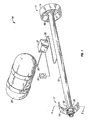
- FIG. 1 is a schematic perspective elevational view, partly in cross section, illustrating one form of an axle of a vehicle having a high temperature warning system connected to the wheel assemblies;
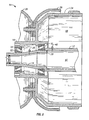
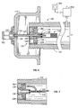
- FIG. 2 is an enlarged elevational view, in cross section, taken along the line 2-2 of FIG. 1 illustrating a wheel assembly and a high temperature warning system;
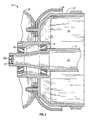
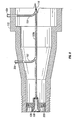
- FIG. 3 is a view similar to FIG. 2 illustrating another form of the present invention.
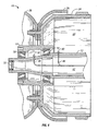
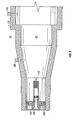
- FIG. 4 is a view similar to FIG. 2 illustrating still another embodiment of the present invention.
- FIG. 5 is a view similar to FIG. 2 illustrating still another form of the present invention.
- FIG. 6 is an elevational cross-sectional view of a portion of an automatic tire inflation system connected to an axle and providing a high temperature warning system;
- FIG. 7 is an elevational view, in cross section; illustrating a partial of an automatic tire inflation system with other forms of high temperature warning systems;
- FIG. 8 is an elevational view in cross section of a part of an automatic tire inflation system showing another form of a temperature warning system; .
- FIG. 9 is an elevational view, in cross section, showing a part of another automatic tire inflation system having another form of a high temperature warning system.
- the reference numeral 10 generally indicates the high temperature warning system of the present invention as installed in a vehicle having an axle 12 and a spindle 13 portion thereof.
- a wheel assembly 11 includes a hub 14 which rotates on inner and outer bearings 16 and 18, respectively, which rotate on inner and outer bearing races, respectively, 20 and 22, and extends through a brake drum 24 and supports a tire and wheel 26.
- the temperature in the bearings 16 and 18, the brake drum 24 and spindle 13 area may reach a temperature to where the tires (not shown) on the tire and wheel 26 or lubricant (not shown) may ignite causing a fire.
- the hub 14 and wheel and tire 26 may detach from the axle 12.
- the temperature warning system 10 of the present invention includes an air pressure supply 28 which is a normal component on a truck or vehicle for various purposes such as brakes, a pressure protection valve 30, a flow switch 32 and an indicator or warning system light 34.
- the air pressure supply preferably includes the axle 12 which is hollow and is connected to supply 28 through line 36 and includes an internal plug 37 at each end of the axle 12 whereby the interior of the axle 12 forms part of the air pressure supply.
- One or more normally closed valves such as heat sensitive pressure barriers comprising a fusible plug 38 and 40, are connected between the inside 42 and the outside 44 of the pressure supply.
- the heat sensitive pressure barriers are fusible plugs 38 and 40 which also form a heat sensitive control for actuating the opening and closing of the valves or barriers 38 and 40 upon a predetermined temperature.
- the fusible plugs 38 and 40 include an eutectic alloy, which melts sharply at a predetermined temperature. Thus, when the area in which the plugs 38 and 40 are installed reach a certain temperatures the alloy will melt, creating an air leak from the air supply tank 28. This will be detected by the flow switch 32 which actuates the warning system light 34 which is positioned adjacent the driver of the vehicle to indicate a problem.
- the plugs 38 and 40 are mounted adjacent to the wheel assemblies 11 for measuring the temperature of the wheel assembly 11.
- the plugs 38 and 40 extend radially outwardly from the axle 12 and spindle 13 and are positioned adjacent the bearings 20, 22 and brake drum 24.
- any type of fusible plug is satisfactory, one sold under the trademark LEEKPRUF sold by the Mueller Refrigeration Company, Inc. is satisfactory.
- other types of thermally operated valves may be used for opening the air supply such as a thermally electric switch which operates an electric operated valve.
- FIG. 3 another form of the present invention is shown which is similar to FIG. 2 with the exception that a heat sensitive pressure barrier or fusible plug 38a is positioned in the end plug 37.
- a heat sensitive pressure barrier or fusible plug 38a is positioned in the end plug 37.
- This provides a simplified manufacturing and construction form, but yet the heat sensitive pressure barrier and control is mounted sufficiently close to the heat assembly 13 for measuring the temperature of the wheel hub assemblies 11.
- FIG. 4 still another form of the present invention is shown in which, instead of the interior 42 of the axle 12 forming a part of the air pressure system air supply conduits or tubings 46 and 48 connected between the air line 36 ( FIG. 1 ) and the fusible plugs 38 and 40, respectively.
- FIG. 5 another form is shown in which again the axle 12 does not form an air supply but an air conduit or tubing 50 is connected between the air line 36 ( FIG. 1 ) and a fusible plug 38b in the end plug 37.
- the end plugs 37 in the embodiments of FIGS. 4 and 5 serve the purpose of preventing debris in the inside of the axle 12.
- FIGS. 1-5 provide a stand alone system for vehicles such as trailer tractors
- the warning system is particularly and easily adapted for use with an automatic tire inflation system which already includes an air pressure supply and a warning system measuring the loss of air pressure from the system or tires. Therefore, the combination of the temperature warning system of the present invention with an automatic tire inflation system provides a means of informing the vehicle operator of temperature problems.
- the present invention can be used with various types of automatic tire inflation systems, it is useful with the system shown in FIG. 6 and more fully described and illustrated in US 2004/0000364 A1 .
- the reference numeral 100 generally indicates the rotary air connection for supplying air from an air supply on a vehicle in an automatic tire inflation system for a vehicle to the rotating tires.
- the numeral 112 generally indicates one axle or spindle, a hub cap 114 is provided at each end of the axle 112 for retaining lubricant in the wheel bearings and an air supply 116, either directly in the axle 112, or through an interior conduit (not shown) in the inside of the axle 112 supplies air to the rotary air connection through the inside of the axle.
- a pneumatic rotary union generally indicated by the reference 120 is supported and positioned in the center end of the axle 120, such as by force fit plug 220, but sealingly engages the interior of the axle 112 by a seal 124 if air is injected directly into the inside of the axle 112.
- the rotary union 120 has a first stationary part 128 having a passageway 136 therethrough.
- the passageway 136 is in communication with the air supply 116.
- a first resilient rotary seal 138 is supported in the passageway 136 and encircles the passageway 136.
- the union 120 includes a second rotatable part including a tubular member 142 having a first end 144 and a second end 146.
- the second end 146 is coaxially extendable through and is longitudinally and rotationally movable in the passageway 136 and sealably engages the rotary seal 138 and is in communication with the air supply 116.
- the first end 144 of the tubular member 142 is sealably connected to the air connection or T-body 152 on the hub cap 144 through a seal 150.
- An air connection 152 or T-body is provided on the hub cap 144 for connection to the tire or tires at the end of the axle 112.
- the end 144 of the tubular member 142 includes a shoulder which includes a bearing 101.
- air 116 is supplied through the stationary part 128 of the rotary union 120.
- the hub cap 114 rotates with the wheels relative to the tubular member 142.
- the automatic tire inflation system 100 of FIG. 6 already includes an air pressure supply 116 and any suitable warning system consisting of a flow switch 32a and a warning indicator light 34a.
- a heat sensitive pressure barrier 38c at a location near the wheel bearings or brake area on the spindle 113 provides a temperature warning system of the present invention. Again, if the spindle reaches a predetermined temperature the fusible plug melts releasing air from the air supply 116 and actuates the warning system light 34a for notification of the operator. The operator can quickly determine whether the warning system 34a is indicating a pressure leak in the tires or a high temperature problem in the wheel hub area.
- FIG. 7 another form of the present invention is shown having an automatic tire inflation system of which only stationary part 128 of the rotary connection is shown.
- the air supply 116 is supplied through an internal conduit or tubing 150 which supplies air to the passageway 136 in the member 128 and also supplies air to a heat sensitive pressure barrier or fusible plug 38d.
- FIG. 8 a further form of the present invention is shown including an automatic tire inflation system in which only the stationary part 128 of the rotary connection is shown.
- the air supply 116 is supplied to an air tubing or conduit 150a inside of the axle 112 and is connected to the passageway 136 in the part 128.
- Heat sensitive pressure barriers or fusible plugs 38e and 40e are provided radially extending out of the axle 112 and are connected to the air supply tubing 150a by air tubes 152 and 154.
- FIG. 9 another form of the present invention is shown which includes an automatic tire inflation system in which only the stationary part 128 of the rotary connection is shown.
- the interior of the hollow axle 112 forms part of the air supply for supplying air by 116 to the passageway 136.
- heat sensitive pressure barriers or plugs 38f and 40f are provided radially extending through the wall of the axle 112 or spindle.
Landscapes
- Engineering & Computer Science (AREA)
- Mechanical Engineering (AREA)
- Rolling Contact Bearings (AREA)
- Valves And Accessory Devices For Braking Systems (AREA)
- Tires In General (AREA)
Claims (8)
- Hochtemperaturwarnsystem (10), welches an einem Fahrzeug angebracht ist, welches eine hohle Achse (12), die mit einer Druckluftzuführung (28, 46, 48) zum Zuführen von Luft zu der Innenseite (42) der Achse verbunden ist, eine Radnabe (14), welche an Lagern (16, 18) an der Achse drehbar angebracht ist, ein automatisches Reifenaufpumpsystem zum Bereitstellen von Luft für einen sich auf der Radnabe drehenden Reifen und eine Drehverbindung in Verbindung zwischen dem Reifen und Luft innerhalb der Achse (12) aufweist, wobei das Hochtemperaturwarnsystem umfasst:ein normalerweise geschlossenes Ventil (38, 40), welches zwischen der Innenseite und Außenseite der Achse (12) in Verbindung mit der Luft in der Achse (12) angeschlossen ist;eine wärmeempfindliche Steuerung, welche mit dem Ventil (38, 40) verbunden ist und dieses aufgrund einer vorbestimmten Temperatur offen ansteuert, wobei die Steuerung an der Achse (12) in einer wärmeaustauschenden Beziehung mit der Achse (12) angebracht ist und benachbart zu einer Radendanordnung (11) zum Messen der Temperatur der Radendanordnung (11) und Achse (12) angeordnet ist; undein Warnsystem (32, 34), welches mit der Luftzuführung für eine Auslösung aufgrund eines Öffnens des Ventils verbunden ist.
- System nach Anspruch 1, wobei die hohle Achse (12) an den Enden mit einem Stopfen (37) verschlossen ist und die wärmeempfindliche Steuerung eine wärmeempfindliche Druckabsperrung (38) aufweist, welche in jedem Stopfen (37) angeordnet ist.
- System nach Anspruch 1, wobei die wärmeempfindliche Steuerung eine oder mehrere wärmeempfindliche Druckabsperrungen aufweist, welche in der Achse (12) benachbart zu den Lagern (16, 18) oder Bremsen (24) in der Radanordnung (11) angeordnet sind.
- System nach Anspruch 1, wobei die Druckluftzuführung eine Rohrleitung (46, 48) aufweist, welche in der Achse (12) angeordnet ist und mit einer oder mehreren wärmeempfindlichen Druckabsperrungen (38, 40) verbunden ist.
- System nach Anspruch 4, wobei die Druckabsperrungen (38, 40) benachbart zu Lagern (16, 18) oder Bremsen (24) in der Radanordnung (11) angeordnet sind.
- System nach Anspruch 3, wobei eine Druckabsperrung in jedem Ende der hohlen Achse (12) angeordnet ist.
- Hochtemperaturwarnsystem, welches an einem Fahrzeug angebracht ist, welches eine Achse und eine daran drehbare Radendanordnung (11) aufweist, wobei das Hochtemperaturwarnsystem umfasst:eine Druckluftzuführung in der Achse, die mit einer Druckquelle (28) an dem Fahrzeug verbunden ist;ein normalerweise geschlossenes Ventil (38, 40), welches mit der Druckluftzuführung verbunden ist, wobei das Ventil (38, 40) in der Lage ist, sich aufgrund einer Betätigung zu öffnen, um Luft von der Druckluftzuführung abzugeben;einen thermoelektrischen Schalter, welcher mit dem Ventil (38, 40) verbunden ist, wobei der thermoelektrische Schalter in der Lage ist, das Ventil (38, 40) aufgrund einer vorbestimmten Temperatur zu betätigen, wobei der thermoelektrische Schalter benachbart zu der Radendanordnung (11) angebracht ist, um eine Erfassung von Wärme von der Radendanordnung (11) zu ermöglichen; undein Warnsystem, welches mit der Druckluftzuführung verbunden ist, wobei das Warnsystem in der Lage ist, aufgrund eines Öffnens des Ventils (38, 40) auszulösen.
- Hochtemperaturwarnsystem, welches an einem Fahrzeug angebracht ist, welches eine Achse und eine daran drehbare Radendanordnung (11) aufweist, wobei das Hochtemperaturwarnsystem umfasst:eine Druckluftzuführung in der Achse (12), welche mit einer Druckquelle (28) an dem Fahrzeug verbunden ist; undein thermisch betätigtes, normalerweise geschlossenes Ventil (38, 40), welches mit der Druckluftzuführung verbunden ist, wobei das Ventil (38, 40) in der Lage ist, sich aufgrund einer vorbestimmten Temperatur zu öffnen, um Luft von der Druckluftzuführung abzugeben, wobei das Ventil (38, 40) benachbart zu der Radendordnung (11) angebracht ist, um eine Erfassung von Wärme von der Radendordnung (11) zu ermöglichen.
Applications Claiming Priority (2)
| Application Number | Priority Date | Filing Date | Title |
|---|---|---|---|
| US10/657,886 US6892778B2 (en) | 2003-09-09 | 2003-09-09 | Wheel end assembly high-temperature warning system |
| PCT/US2004/028427 WO2005027065A2 (en) | 2003-09-09 | 2004-09-01 | Wheel end assembly high-temperature warning system |
Publications (3)
| Publication Number | Publication Date |
|---|---|
| EP1663673A2 EP1663673A2 (de) | 2006-06-07 |
| EP1663673A4 EP1663673A4 (de) | 2011-05-18 |
| EP1663673B1 true EP1663673B1 (de) | 2012-10-24 |
Family
ID=34226663
Family Applications (1)
| Application Number | Title | Priority Date | Filing Date |
|---|---|---|---|
| EP04782843A Expired - Lifetime EP1663673B1 (de) | 2003-09-09 | 2004-09-01 | Randendenanordnung mit hochtemperaturwarnsystem |
Country Status (9)
| Country | Link |
|---|---|
| US (5) | US6892778B2 (de) |
| EP (1) | EP1663673B1 (de) |
| CN (1) | CN100513210C (de) |
| AU (2) | AU2004273472B2 (de) |
| BR (1) | BRPI0413725B1 (de) |
| CA (1) | CA2538287C (de) |
| ES (1) | ES2393677T3 (de) |
| WO (1) | WO2005027065A2 (de) |
| ZA (1) | ZA200601911B (de) |
Families Citing this family (45)
| Publication number | Priority date | Publication date | Assignee | Title |
|---|---|---|---|---|
| US6938658B2 (en) * | 2003-06-09 | 2005-09-06 | Airgo Ip, Llc | Expandable spindle plug assembly for use with automatic tire inflation systems |
| US6892778B2 (en) * | 2003-09-09 | 2005-05-17 | Mark K. Hennig | Wheel end assembly high-temperature warning system |
| DE102005004955A1 (de) * | 2005-02-03 | 2006-08-17 | Daimlerchrysler Ag | Verfahren zur Reifendruckregelung bei einem Kraftfahrzeug |
| DE102005062095B4 (de) * | 2005-12-22 | 2009-07-16 | Saf-Holland Gmbh | Radnabenanordnung |
| DE102007005765A1 (de) * | 2007-02-06 | 2008-08-14 | Fereshteh Saadat | Radachse und Antriebs- oder Gelenkwelle |
| DE102008009283B4 (de) * | 2008-02-15 | 2021-07-29 | Schaeffler Technologies AG & Co. KG | Radlagervorrichtung für ein Kraftfahrzeug |
| WO2009140490A1 (en) * | 2008-05-16 | 2009-11-19 | Hendrickson Usa, L.L.C. | Vehicle temperature warning system |
| MX2010011328A (es) * | 2008-05-16 | 2011-02-15 | Hendrickson Usa Llc | Union giratoria y tapa de cubo integradas. |
| WO2011026105A1 (en) * | 2009-08-31 | 2011-03-03 | Equalaire Systems, Inc. | Axle spindle for tire inflation system |
| CN105835635B (zh) * | 2010-07-29 | 2018-08-07 | 伊夸莱尔系统公司 | 转向车桥高温报警系统 |
| US20120032793A1 (en) * | 2010-07-30 | 2012-02-09 | Frank Joseph Sonzala | Visual wheel end assembly high-temperature warning system |
| US9375985B2 (en) | 2010-08-23 | 2016-06-28 | Equalaire Systems, Inc. | Valve stem with auxiliary port |
| MX348864B (es) | 2010-11-19 | 2017-07-03 | Equalaire Systems Inc | Sistema para administración de neumáticos. |
| DE102011007231B4 (de) * | 2011-04-12 | 2013-09-26 | Saf-Holland Gmbh | Radlageranordnung, insbesondere Radlageranordnung für Nutzfahrzeuge |
| CA3021105C (en) | 2011-06-07 | 2019-11-05 | Equalaire System, Inc. | System and method using a pressure reduction valve |
| FR2978699B1 (fr) * | 2011-08-02 | 2014-02-28 | Nexter Mechanics | Dispositif d'etancheite tournant et bague d'etancheite pour un tel dispositif |
| EP2653323B1 (de) * | 2012-04-19 | 2016-03-23 | DANA ITALIA S.p.A | Achsanordnung für Reifenfüllsystem |
| US9136683B2 (en) | 2012-07-18 | 2015-09-15 | Elwha Llc | Adjustable suspension of transmission lines |
| US9404806B2 (en) * | 2013-03-14 | 2016-08-02 | The Boeing Company | Methods and apparatus to monitor components of an aircraft landing system |
| US9789739B1 (en) | 2013-04-23 | 2017-10-17 | Equalaire Systems, Inc. | Small trailer tire inflation system |
| CN110561987A (zh) | 2013-11-11 | 2019-12-13 | 伊夸莱尔系统公司 | 车辆轮胎充气系统 |
| DE102013223436B4 (de) * | 2013-11-18 | 2015-12-31 | Saf-Holland Gmbh | Radlageranordnung |
| DE102014001373A1 (de) * | 2014-02-04 | 2015-08-06 | Gv Engineering Gmbh | Fahrzeugachsbaugruppe mit integrierter Druckmittelleitung zur Reifenbefüllung |
| KR20170029520A (ko) | 2014-07-02 | 2017-03-15 | 다나 이탈리아 에스피에이 | 중앙 타이어 팽창 시스템용 회전 밀봉 |
| US9352621B2 (en) * | 2014-07-15 | 2016-05-31 | Arvinmeritor Technology, Llc | Tire inflation system having a pressure relief valve |
| DE102014218331B4 (de) * | 2014-09-12 | 2018-11-08 | Saf-Holland Gmbh | Achseinheit |
| DE102014218325B4 (de) | 2014-09-12 | 2021-10-28 | Saf-Holland Gmbh | Achseinheit |
| CA2957894C (en) * | 2014-09-12 | 2019-02-19 | Hendrickson Usa, L.L.C. | Wheel end sensor for heavy-duty vehicles |
| US10308352B2 (en) | 2014-12-12 | 2019-06-04 | Borealis Technical Limited | Monitoring system for aircraft drive wheel system |
| JP2019502061A (ja) * | 2015-10-30 | 2019-01-24 | ローベルト ボツシユ ゲゼルシヤフト ミツト ベシユレンクテル ハフツングRobert Bosch Gmbh | トレーラ軸においてホイールハブ温度及び走行距離を監視するためのシステム及び方法 |
| JP6642917B2 (ja) * | 2016-06-30 | 2020-02-12 | 公益財団法人鉄道総合技術研究所 | 鉄道車両用中空車軸の損傷検出システム |
| CN114701303A (zh) | 2016-10-19 | 2022-07-05 | 伊夸莱尔系统公司 | 流体导管 |
| US20190263197A1 (en) * | 2016-10-20 | 2019-08-29 | Equalaire Systems, Inc. | Tire Inflation System Visual Flow Indicator |
| US11254170B2 (en) | 2017-04-13 | 2022-02-22 | Tesla, Inc. | Automatic tire inflation system with thru-hub air feed |
| US20180370280A1 (en) * | 2017-06-26 | 2018-12-27 | GM Global Technology Operations LLC | System and method for predicting failure of a wheel bearing in vehicle |
| US20210206406A1 (en) * | 2018-05-25 | 2021-07-08 | Kawasaki Jukogyo Kabushiki Kaisha | Wheelset rfid tag unit |
| WO2020028598A1 (en) | 2018-07-31 | 2020-02-06 | Equalaire Systems, Inc. | Digital wheel end assembly temperature monitoring system |
| CN109079423A (zh) * | 2018-09-26 | 2018-12-25 | 合肥宽信机电有限公司 | 一种用于车桥壳加工的全自动轴头压机装置 |
| DE102019213799A1 (de) | 2019-09-11 | 2021-03-11 | Aktiebolaget Skf | Messverfahren für die Temperatur eines mechanischen Teils eines Radendes eines Automobilfahrzeugs und entsprechende Vorrichtung |
| WO2021180575A1 (en) * | 2020-03-12 | 2021-09-16 | Volvo Truck Corporation | A method and a system for determining that a failure has occurred at or in a wheel end bearing of a vehicle |
| CA3125657C (en) * | 2020-07-22 | 2025-11-18 | Hyundai Translead | THERMAL MONITORING SYSTEM FOR A TRAILER WHEEL AREA |
| US20230373255A1 (en) * | 2021-07-22 | 2023-11-23 | Hyundai Translead | Thermal monitoring of trailers |
| US12036823B2 (en) | 2022-01-07 | 2024-07-16 | Arvinmeritor Technology, Llc | Tire inflation system and connection arrangement |
| US12179519B2 (en) * | 2022-01-07 | 2024-12-31 | Arvinmeritor Technology, Llc | Axle assembly having a spindle plug and a sleeve |
| US12298189B2 (en) | 2023-08-03 | 2025-05-13 | Jacob Peters | Axle temperature monitoring system |
Family Cites Families (37)
| Publication number | Priority date | Publication date | Assignee | Title |
|---|---|---|---|---|
| US2693841A (en) * | 1951-03-07 | 1954-11-09 | Mack Mfg Corp | Tire inflation and deflation system |
| US3645479A (en) * | 1970-03-16 | 1972-02-29 | Boeing Co | Aircraft tire explosion prevention system |
| US3811457A (en) * | 1971-09-30 | 1974-05-21 | Goodyear Tire & Rubber | Over pressurization release device and valve |
| GB1428632A (en) * | 1973-02-20 | 1976-03-17 | Nissan Motor | Tyre air pressure sensor |
| US3898638A (en) * | 1973-08-09 | 1975-08-05 | Robert A Deane | Differential temperature sensor system and improvements in a fluid flow detector |
| US4004271A (en) * | 1974-12-13 | 1977-01-18 | General Motors Corporation | Low tire pressure warning system |
| US4058185A (en) * | 1976-08-09 | 1977-11-15 | Ploeger Kenneth C | Automatic wheel bearing lubricator |
| US4333004A (en) * | 1980-02-19 | 1982-06-01 | Dataproducts New England, Inc. | Detecting ice forming weather conditions |
| US4700763A (en) * | 1984-03-29 | 1987-10-20 | The United States Of America As Represented By The Secretary Of The Air Force | Remotely controlled aircraft tire inflation/deflation valve |
| US4812826A (en) * | 1987-03-26 | 1989-03-14 | Carnegie-Mellon University | Thermal sensor for detection of railroad bearing failures |
| US4947786A (en) * | 1989-05-15 | 1990-08-14 | Maynard Raymond L | Overheated-axle indicator device |
| EP0457028B1 (de) | 1990-05-17 | 1995-12-20 | Equalaire Systems, Inc. | Luftkontrollsystem für Fahrzeugreifen |
| US5293919A (en) * | 1991-11-18 | 1994-03-15 | Hughes Aircraft Company | Self-regulating tire pressure system and method |
| US5200697B1 (en) * | 1991-11-27 | 1996-06-18 | Ntn Toyo Bearing Co Ltd | Hub and bearing assembly with integrated rotation sensor including a tone ring and annular transducer |
| US5309969A (en) * | 1991-12-17 | 1994-05-10 | Chander Mittal | Apparatus for repeatable adjustment of tire pressure |
| US5587698A (en) * | 1992-02-05 | 1996-12-24 | Genna; Robert A. | Automatic tire pressure control system for a vehicle |
| US5429167A (en) * | 1993-08-13 | 1995-07-04 | Oshkosh Truck Corporation | Universal central tire inflation system for trailers |
| US5377736A (en) | 1993-11-18 | 1995-01-03 | Marks-Rms, Inc. | Driven axle vehicle inflation system |
| GB2286804A (en) * | 1994-02-26 | 1995-08-30 | Dunlop Ltd | Fusible plug for pressure vessels |
| US5584949A (en) * | 1994-05-06 | 1996-12-17 | Ingram; Anthony L. | Air inflation system for trailer axles |
| US5538062A (en) | 1994-08-12 | 1996-07-23 | Marks-Rms, Inc. | Pnuematic tire inflation system |
| US5492393A (en) * | 1994-09-15 | 1996-02-20 | Skf Usa Inc. | Hub cap vent device |
| US5553647A (en) * | 1994-12-14 | 1996-09-10 | Hayes Wheels International, Inc. | Central tire inflation system |
| US5584773A (en) * | 1995-07-12 | 1996-12-17 | Caterpillar Inc. | Fluid circulatory system for an axle assembly |
| US5565065A (en) * | 1995-11-28 | 1996-10-15 | Wang; Chin-Tu | Distilled water supply device |
| US5767398A (en) | 1996-11-20 | 1998-06-16 | Equalaire Systems, Inc. | Tire leak detector for an automatic inflation system |
| CA2226829C (en) * | 1997-03-11 | 2000-08-29 | John Mantini | Early warning device for tire rims and hub assemblies |
| US6105645A (en) * | 1998-05-14 | 2000-08-22 | Ingram; Anthony L. | Rotary union assembly for use in air pressure inflation systems for tractor trailer tires |
| US6401743B1 (en) * | 1999-08-25 | 2002-06-11 | Vehicle Inflation Technologies | Automatic tire inflation system having a pressure regulator with an integrated leak detection switch |
| US6145559A (en) * | 1999-09-03 | 2000-11-14 | Accessio, Ltd. | Axle and hub assembly for automatic tire inflation pressurization system |
| US6670890B2 (en) * | 2000-02-03 | 2003-12-30 | Meritor Heavy Vehicle Technology Llc | Thermally activated sensor system |
| US6435238B1 (en) * | 2001-03-22 | 2002-08-20 | Equalaire Systems, Inc. | Combination of an automatic tire inflation system and anti-locking braking system |
| US6759963B2 (en) * | 2001-05-08 | 2004-07-06 | Meritor Heavy Vehicle Technology, Llc | Wheel bearing temperature indicator |
| US6546892B2 (en) * | 2001-06-07 | 2003-04-15 | Walter P. Kelly, Jr. | Overheating axle warning device |
| US6698482B2 (en) * | 2002-07-01 | 2004-03-02 | Equalaire Systems, Inc. | Rotary air connection with bearing for tire inflation system |
| US6892778B2 (en) * | 2003-09-09 | 2005-05-17 | Mark K. Hennig | Wheel end assembly high-temperature warning system |
| US20050194079A1 (en) * | 2004-03-08 | 2005-09-08 | Equalaire Systems, Inc. | Easy maintenance automatic tire inflation system |
-
2003
- 2003-09-09 US US10/657,886 patent/US6892778B2/en not_active Expired - Lifetime
-
2004
- 2004-09-01 CN CNB2004800298301A patent/CN100513210C/zh not_active Expired - Fee Related
- 2004-09-01 AU AU2004273472A patent/AU2004273472B2/en not_active Ceased
- 2004-09-01 WO PCT/US2004/028427 patent/WO2005027065A2/en not_active Ceased
- 2004-09-01 EP EP04782843A patent/EP1663673B1/de not_active Expired - Lifetime
- 2004-09-01 BR BRPI0413725A patent/BRPI0413725B1/pt not_active IP Right Cessation
- 2004-09-01 ES ES04782843T patent/ES2393677T3/es not_active Expired - Lifetime
- 2004-09-01 CA CA002538287A patent/CA2538287C/en not_active Expired - Lifetime
-
2005
- 2005-01-20 US US11/039,551 patent/US7416005B2/en not_active Expired - Lifetime
-
2006
- 2006-03-06 ZA ZA200601911A patent/ZA200601911B/en unknown
-
2008
- 2008-07-01 US US12/166,123 patent/US8186403B2/en not_active Expired - Fee Related
-
2011
- 2011-03-25 AU AU2011201370A patent/AU2011201370B2/en not_active Ceased
-
2012
- 2012-03-30 US US13/435,924 patent/US8919401B2/en not_active Expired - Lifetime
-
2014
- 2014-11-26 US US14/555,241 patent/US9227472B2/en not_active Expired - Fee Related
Also Published As
| Publication number | Publication date |
|---|---|
| CA2538287A1 (en) | 2005-03-24 |
| CN1867466A (zh) | 2006-11-22 |
| US7416005B2 (en) | 2008-08-26 |
| AU2011201370A1 (en) | 2011-04-28 |
| US20120212039A1 (en) | 2012-08-23 |
| BRPI0413725B1 (pt) | 2017-02-14 |
| US8186403B2 (en) | 2012-05-29 |
| EP1663673A4 (de) | 2011-05-18 |
| CA2538287C (en) | 2009-11-24 |
| AU2011201370B2 (en) | 2012-08-02 |
| US6892778B2 (en) | 2005-05-17 |
| US20150197124A1 (en) | 2015-07-16 |
| US20050052074A1 (en) | 2005-03-10 |
| CN100513210C (zh) | 2009-07-15 |
| HK1098989A1 (zh) | 2007-08-03 |
| ZA200601911B (en) | 2007-05-30 |
| US9227472B2 (en) | 2016-01-05 |
| WO2005027065A3 (en) | 2005-08-11 |
| EP1663673A2 (de) | 2006-06-07 |
| US20090242092A1 (en) | 2009-10-01 |
| WO2005027065A2 (en) | 2005-03-24 |
| ES2393677T3 (es) | 2012-12-27 |
| BRPI0413725A (pt) | 2006-10-17 |
| AU2004273472B2 (en) | 2011-04-28 |
| AU2011201370A2 (en) | 2011-06-23 |
| US20050156463A1 (en) | 2005-07-21 |
| AU2004273472A1 (en) | 2005-03-24 |
| US8919401B2 (en) | 2014-12-30 |
Similar Documents
| Publication | Publication Date | Title |
|---|---|---|
| EP1663673B1 (de) | Randendenanordnung mit hochtemperaturwarnsystem | |
| US8910683B2 (en) | Steer axle high-temperature warning system | |
| HK1225350A1 (en) | Steer axle high-temperature warning system | |
| AU2012244247B2 (en) | Wheel end assembly high-temperature warning system | |
| AU2014200555B2 (en) | Wheel end assembly high-temperature warning system | |
| AU2011283058B2 (en) | Steer axle high-temperature warning system | |
| HK1098989B (en) | Wheel end assembly high-temperature warning system | |
| MXPA06002645A (en) | Wheel end assembly high-temperature warning system | |
| HK1180284B (en) | Steer axle high-temperature warning system |
Legal Events
| Date | Code | Title | Description |
|---|---|---|---|
| PUAI | Public reference made under article 153(3) epc to a published international application that has entered the european phase |
Free format text: ORIGINAL CODE: 0009012 |
|
| 17P | Request for examination filed |
Effective date: 20060327 |
|
| AK | Designated contracting states |
Kind code of ref document: A2 Designated state(s): AT BE BG CH CY CZ DE DK EE ES FI FR GB GR HU IE IT LI LU MC NL PL PT RO SE SI SK TR |
|
| DAX | Request for extension of the european patent (deleted) | ||
| A4 | Supplementary search report drawn up and despatched |
Effective date: 20110419 |
|
| RIC1 | Information provided on ipc code assigned before grant |
Ipc: B60C 23/00 20060101AFI20060329BHEP Ipc: F16K 17/38 20060101ALI20110413BHEP |
|
| 17Q | First examination report despatched |
Effective date: 20111110 |
|
| REG | Reference to a national code |
Ref country code: DE Ref legal event code: R079 Ref document number: 602004039799 Country of ref document: DE Free format text: PREVIOUS MAIN CLASS: B60C0023000000 Ipc: B60C0023200000 |
|
| RIC1 | Information provided on ipc code assigned before grant |
Ipc: B60C 23/20 20060101AFI20120313BHEP Ipc: B61K 9/04 20060101ALI20120313BHEP Ipc: F16K 17/38 20060101ALI20120313BHEP Ipc: B60C 23/00 20060101ALI20120313BHEP |
|
| GRAP | Despatch of communication of intention to grant a patent |
Free format text: ORIGINAL CODE: EPIDOSNIGR1 |
|
| GRAS | Grant fee paid |
Free format text: ORIGINAL CODE: EPIDOSNIGR3 |
|
| GRAA | (expected) grant |
Free format text: ORIGINAL CODE: 0009210 |
|
| AK | Designated contracting states |
Kind code of ref document: B1 Designated state(s): AT BE BG CH CY CZ DE DK EE ES FI FR GB GR HU IE IT LI LU MC NL PL PT RO SE SI SK TR |
|
| REG | Reference to a national code |
Ref country code: GB Ref legal event code: FG4D |
|
| REG | Reference to a national code |
Ref country code: CH Ref legal event code: EP |
|
| REG | Reference to a national code |
Ref country code: AT Ref legal event code: REF Ref document number: 580710 Country of ref document: AT Kind code of ref document: T Effective date: 20121115 |
|
| REG | Reference to a national code |
Ref country code: IE Ref legal event code: FG4D |
|
| REG | Reference to a national code |
Ref country code: DE Ref legal event code: R096 Ref document number: 602004039799 Country of ref document: DE Effective date: 20121220 |
|
| REG | Reference to a national code |
Ref country code: ES Ref legal event code: FG2A Ref document number: 2393677 Country of ref document: ES Kind code of ref document: T3 Effective date: 20121227 |
|
| REG | Reference to a national code |
Ref country code: NL Ref legal event code: T3 |
|
| REG | Reference to a national code |
Ref country code: AT Ref legal event code: MK05 Ref document number: 580710 Country of ref document: AT Kind code of ref document: T Effective date: 20121024 |
|
| PG25 | Lapsed in a contracting state [announced via postgrant information from national office to epo] |
Ref country code: SE Free format text: LAPSE BECAUSE OF FAILURE TO SUBMIT A TRANSLATION OF THE DESCRIPTION OR TO PAY THE FEE WITHIN THE PRESCRIBED TIME-LIMIT Effective date: 20121024 Ref country code: FI Free format text: LAPSE BECAUSE OF FAILURE TO SUBMIT A TRANSLATION OF THE DESCRIPTION OR TO PAY THE FEE WITHIN THE PRESCRIBED TIME-LIMIT Effective date: 20121024 |
|
| PG25 | Lapsed in a contracting state [announced via postgrant information from national office to epo] |
Ref country code: PL Free format text: LAPSE BECAUSE OF FAILURE TO SUBMIT A TRANSLATION OF THE DESCRIPTION OR TO PAY THE FEE WITHIN THE PRESCRIBED TIME-LIMIT Effective date: 20121024 Ref country code: PT Free format text: LAPSE BECAUSE OF FAILURE TO SUBMIT A TRANSLATION OF THE DESCRIPTION OR TO PAY THE FEE WITHIN THE PRESCRIBED TIME-LIMIT Effective date: 20130225 Ref country code: SI Free format text: LAPSE BECAUSE OF FAILURE TO SUBMIT A TRANSLATION OF THE DESCRIPTION OR TO PAY THE FEE WITHIN THE PRESCRIBED TIME-LIMIT Effective date: 20121024 Ref country code: BE Free format text: LAPSE BECAUSE OF FAILURE TO SUBMIT A TRANSLATION OF THE DESCRIPTION OR TO PAY THE FEE WITHIN THE PRESCRIBED TIME-LIMIT Effective date: 20121024 Ref country code: CY Free format text: LAPSE BECAUSE OF FAILURE TO SUBMIT A TRANSLATION OF THE DESCRIPTION OR TO PAY THE FEE WITHIN THE PRESCRIBED TIME-LIMIT Effective date: 20121024 Ref country code: GR Free format text: LAPSE BECAUSE OF FAILURE TO SUBMIT A TRANSLATION OF THE DESCRIPTION OR TO PAY THE FEE WITHIN THE PRESCRIBED TIME-LIMIT Effective date: 20130125 |
|
| PG25 | Lapsed in a contracting state [announced via postgrant information from national office to epo] |
Ref country code: AT Free format text: LAPSE BECAUSE OF FAILURE TO SUBMIT A TRANSLATION OF THE DESCRIPTION OR TO PAY THE FEE WITHIN THE PRESCRIBED TIME-LIMIT Effective date: 20121024 |
|
| PG25 | Lapsed in a contracting state [announced via postgrant information from national office to epo] |
Ref country code: DK Free format text: LAPSE BECAUSE OF FAILURE TO SUBMIT A TRANSLATION OF THE DESCRIPTION OR TO PAY THE FEE WITHIN THE PRESCRIBED TIME-LIMIT Effective date: 20121024 Ref country code: CZ Free format text: LAPSE BECAUSE OF FAILURE TO SUBMIT A TRANSLATION OF THE DESCRIPTION OR TO PAY THE FEE WITHIN THE PRESCRIBED TIME-LIMIT Effective date: 20121024 Ref country code: SK Free format text: LAPSE BECAUSE OF FAILURE TO SUBMIT A TRANSLATION OF THE DESCRIPTION OR TO PAY THE FEE WITHIN THE PRESCRIBED TIME-LIMIT Effective date: 20121024 Ref country code: EE Free format text: LAPSE BECAUSE OF FAILURE TO SUBMIT A TRANSLATION OF THE DESCRIPTION OR TO PAY THE FEE WITHIN THE PRESCRIBED TIME-LIMIT Effective date: 20121024 Ref country code: BG Free format text: LAPSE BECAUSE OF FAILURE TO SUBMIT A TRANSLATION OF THE DESCRIPTION OR TO PAY THE FEE WITHIN THE PRESCRIBED TIME-LIMIT Effective date: 20130124 |
|
| PG25 | Lapsed in a contracting state [announced via postgrant information from national office to epo] |
Ref country code: RO Free format text: LAPSE BECAUSE OF FAILURE TO SUBMIT A TRANSLATION OF THE DESCRIPTION OR TO PAY THE FEE WITHIN THE PRESCRIBED TIME-LIMIT Effective date: 20121024 |
|
| PLBE | No opposition filed within time limit |
Free format text: ORIGINAL CODE: 0009261 |
|
| STAA | Information on the status of an ep patent application or granted ep patent |
Free format text: STATUS: NO OPPOSITION FILED WITHIN TIME LIMIT |
|
| 26N | No opposition filed |
Effective date: 20130725 |
|
| REG | Reference to a national code |
Ref country code: DE Ref legal event code: R097 Ref document number: 602004039799 Country of ref document: DE Effective date: 20130725 |
|
| PG25 | Lapsed in a contracting state [announced via postgrant information from national office to epo] |
Ref country code: MC Free format text: LAPSE BECAUSE OF FAILURE TO SUBMIT A TRANSLATION OF THE DESCRIPTION OR TO PAY THE FEE WITHIN THE PRESCRIBED TIME-LIMIT Effective date: 20121024 |
|
| REG | Reference to a national code |
Ref country code: CH Ref legal event code: PL |
|
| REG | Reference to a national code |
Ref country code: IE Ref legal event code: MM4A |
|
| PG25 | Lapsed in a contracting state [announced via postgrant information from national office to epo] |
Ref country code: LI Free format text: LAPSE BECAUSE OF NON-PAYMENT OF DUE FEES Effective date: 20130930 Ref country code: IE Free format text: LAPSE BECAUSE OF NON-PAYMENT OF DUE FEES Effective date: 20130901 Ref country code: CH Free format text: LAPSE BECAUSE OF NON-PAYMENT OF DUE FEES Effective date: 20130930 |
|
| PG25 | Lapsed in a contracting state [announced via postgrant information from national office to epo] |
Ref country code: TR Free format text: LAPSE BECAUSE OF FAILURE TO SUBMIT A TRANSLATION OF THE DESCRIPTION OR TO PAY THE FEE WITHIN THE PRESCRIBED TIME-LIMIT Effective date: 20121024 |
|
| PG25 | Lapsed in a contracting state [announced via postgrant information from national office to epo] |
Ref country code: LU Free format text: LAPSE BECAUSE OF NON-PAYMENT OF DUE FEES Effective date: 20130901 Ref country code: HU Free format text: LAPSE BECAUSE OF FAILURE TO SUBMIT A TRANSLATION OF THE DESCRIPTION OR TO PAY THE FEE WITHIN THE PRESCRIBED TIME-LIMIT; INVALID AB INITIO Effective date: 20040901 |
|
| REG | Reference to a national code |
Ref country code: FR Ref legal event code: PLFP Year of fee payment: 13 |
|
| REG | Reference to a national code |
Ref country code: FR Ref legal event code: PLFP Year of fee payment: 14 |
|
| REG | Reference to a national code |
Ref country code: FR Ref legal event code: PLFP Year of fee payment: 15 |
|
| PGFP | Annual fee paid to national office [announced via postgrant information from national office to epo] |
Ref country code: IT Payment date: 20190917 Year of fee payment: 16 Ref country code: NL Payment date: 20190912 Year of fee payment: 16 |
|
| PGFP | Annual fee paid to national office [announced via postgrant information from national office to epo] |
Ref country code: DE Payment date: 20200819 Year of fee payment: 17 Ref country code: GB Payment date: 20200819 Year of fee payment: 17 Ref country code: FR Payment date: 20200715 Year of fee payment: 17 |
|
| PGFP | Annual fee paid to national office [announced via postgrant information from national office to epo] |
Ref country code: ES Payment date: 20201005 Year of fee payment: 17 |
|
| REG | Reference to a national code |
Ref country code: NL Ref legal event code: MM Effective date: 20201001 |
|
| PG25 | Lapsed in a contracting state [announced via postgrant information from national office to epo] |
Ref country code: NL Free format text: LAPSE BECAUSE OF NON-PAYMENT OF DUE FEES Effective date: 20201001 |
|
| PG25 | Lapsed in a contracting state [announced via postgrant information from national office to epo] |
Ref country code: IT Free format text: LAPSE BECAUSE OF NON-PAYMENT OF DUE FEES Effective date: 20200901 |
|
| REG | Reference to a national code |
Ref country code: DE Ref legal event code: R119 Ref document number: 602004039799 Country of ref document: DE |
|
| GBPC | Gb: european patent ceased through non-payment of renewal fee |
Effective date: 20210901 |
|
| PG25 | Lapsed in a contracting state [announced via postgrant information from national office to epo] |
Ref country code: GB Free format text: LAPSE BECAUSE OF NON-PAYMENT OF DUE FEES Effective date: 20210901 Ref country code: FR Free format text: LAPSE BECAUSE OF NON-PAYMENT OF DUE FEES Effective date: 20210930 Ref country code: DE Free format text: LAPSE BECAUSE OF NON-PAYMENT OF DUE FEES Effective date: 20220401 |
|
| REG | Reference to a national code |
Ref country code: ES Ref legal event code: FD2A Effective date: 20221026 |
|
| PG25 | Lapsed in a contracting state [announced via postgrant information from national office to epo] |
Ref country code: ES Free format text: LAPSE BECAUSE OF NON-PAYMENT OF DUE FEES Effective date: 20210902 |