EP1663448B1 - Inlet and distribution device - Google Patents
Inlet and distribution device Download PDFInfo
- Publication number
- EP1663448B1 EP1663448B1 EP04764347A EP04764347A EP1663448B1 EP 1663448 B1 EP1663448 B1 EP 1663448B1 EP 04764347 A EP04764347 A EP 04764347A EP 04764347 A EP04764347 A EP 04764347A EP 1663448 B1 EP1663448 B1 EP 1663448B1
- Authority
- EP
- European Patent Office
- Prior art keywords
- liquid
- gas
- vessel
- mixture
- agglomerator
- Prior art date
- Legal status (The legal status is an assumption and is not a legal conclusion. Google has not performed a legal analysis and makes no representation as to the accuracy of the status listed.)
- Expired - Lifetime
Links
- 238000009826 distribution Methods 0.000 title description 15
- 239000007788 liquid Substances 0.000 claims abstract description 96
- 239000000203 mixture Substances 0.000 claims abstract description 70
- 238000000926 separation method Methods 0.000 claims abstract description 58
- 239000007789 gas Substances 0.000 claims description 59
- 238000007599 discharging Methods 0.000 claims description 5
- 238000000034 method Methods 0.000 claims description 5
- VNWKTOKETHGBQD-UHFFFAOYSA-N methane Chemical compound C VNWKTOKETHGBQD-UHFFFAOYSA-N 0.000 claims description 4
- 238000009827 uniform distribution Methods 0.000 claims description 4
- 238000012856 packing Methods 0.000 claims description 3
- 239000003345 natural gas Substances 0.000 claims description 2
- 239000007787 solid Substances 0.000 claims description 2
- JTJMJGYZQZDUJJ-UHFFFAOYSA-N phencyclidine Chemical class C1CCCCN1C1(C=2C=CC=CC=2)CCCCC1 JTJMJGYZQZDUJJ-UHFFFAOYSA-N 0.000 description 14
- 238000002203 pretreatment Methods 0.000 description 5
- XLYOFNOQVPJJNP-UHFFFAOYSA-N water Substances O XLYOFNOQVPJJNP-UHFFFAOYSA-N 0.000 description 3
- 230000001419 dependent effect Effects 0.000 description 2
- 238000013461 design Methods 0.000 description 2
- 230000000694 effects Effects 0.000 description 2
- 239000012530 fluid Substances 0.000 description 2
- 230000005484 gravity Effects 0.000 description 2
- 239000002184 metal Substances 0.000 description 2
- 238000010008 shearing Methods 0.000 description 2
- 238000005054 agglomeration Methods 0.000 description 1
- 230000002776 aggregation Effects 0.000 description 1
- 239000003638 chemical reducing agent Substances 0.000 description 1
- 238000004891 communication Methods 0.000 description 1
- 230000006866 deterioration Effects 0.000 description 1
- 230000003292 diminished effect Effects 0.000 description 1
- 239000002245 particle Substances 0.000 description 1
- 235000020030 perry Nutrition 0.000 description 1
- 230000008092 positive effect Effects 0.000 description 1
- 150000003839 salts Chemical class 0.000 description 1
- 239000000126 substance Substances 0.000 description 1
- 238000012360 testing method Methods 0.000 description 1
- 239000011800 void material Substances 0.000 description 1
Images


Classifications
-
- B—PERFORMING OPERATIONS; TRANSPORTING
- B01—PHYSICAL OR CHEMICAL PROCESSES OR APPARATUS IN GENERAL
- B01D—SEPARATION
- B01D50/00—Combinations of methods or devices for separating particles from gases or vapours
- B01D50/20—Combinations of devices covered by groups B01D45/00 and B01D46/00
-
- B—PERFORMING OPERATIONS; TRANSPORTING
- B01—PHYSICAL OR CHEMICAL PROCESSES OR APPARATUS IN GENERAL
- B01D—SEPARATION
- B01D45/00—Separating dispersed particles from gases or vapours by gravity, inertia, or centrifugal forces
- B01D45/12—Separating dispersed particles from gases or vapours by gravity, inertia, or centrifugal forces by centrifugal forces
- B01D45/16—Separating dispersed particles from gases or vapours by gravity, inertia, or centrifugal forces by centrifugal forces generated by the winding course of the gas stream, the centrifugal forces being generated solely or partly by mechanical means, e.g. fixed swirl vanes
Definitions
- the present invention relates to a distribution device for pretreatment of a gas/liquid mixture that is to be separated in a separator.
- the present invention also relates to the separator itself and to a method for treating a gas/liquid mixture in a separation vessel.
- Separators are known in the oil and gas industry For separating the incoming mixture of liquid (oil and/or water) and gas into a stream of substantially gas and a stream of substantially liquid. Different separators are known for separating such gas/liquid mixtures.
- a separation vessel in which a number of cyclones are arranged.
- the separation vessel typically comprises an inlet for admitting the liquid/gas mixture, a first outlet for the discharge of a separated heavy fraction of the mixture, i. e. a fraction of the mixture mainly containing the relatively heavy liquid, and an outlet for the discharge of the light fraction of the mixture, i. e. the fraction of the liquid mainly containing the gas. Separation is achieved by forcing the liquid/gas mixture through the cyclones.
- WO 00/25931 discloses a separation vessel wherein a number of so-called axial recycle cyclones are arranged in an upper compartment of the vessel.
- the liquid/mixture enters a lower compartment of the vessel and is forced subsequently through the cyclones.
- the mixture entering an axial cyclone is set into a rotating movement, whereby the heavy fraction is flung against the outer wall of the cyclone, while the light fraction remains in the centre of the cyclone.
- the heavy fraction is then discharged through openings in the outer wall to a so-called downcomer leading the heavy fraction to the lower compartment of the vessel.
- the separated light fraction is discharged via an outlet in the upper compartment of the vessel.
- the liquid/gas mixture will be subjected to a pre-treatment immediately after entering the separation vessel in order to improve the overall separation efficiency of the separator.
- a pre-treatment is also advisable to effect a proper separation of the mixture to the vessel at a rapid rate, since the mixture will otherwise strike the wall of the vessel situated opposite the inlet with considerable force, resulting in liquid particles being entrained to the upper compartment.
- inlet devices For the pre-treatment of the liquid/gas mixture inlet devices are known, in which the mixture entering the vessel is distributed so as to ensure a more uniform distribution over the cross section of the vessel.
- the "Evenflow"vane type inlet device a series of vanes is arranged inside the vessel in the extension of the centre line of the inlet, the vanes being arranged to catch the incoming mixture and deflect it sideways.
- a drawback of the known inlet device is that in practice, especially in case the gas distribution in the inlet piping is poor or in case of a non-optimum pipe layout, the distribution of the mixture out of the device may be insufficient uniform. This will have a negative effect on the separating properties of the separator.
- a further drawback is that the incoming stream will be subjected to additional shear forces meaning that the risk of liquid shearing is increasing. Liquid shearing must be avoided as this reduces the size of the liquid droplets to be separated in the separator. In general, the smaller the droplets are, the harder it will be to get a good separation inside the vessel.
- a further drawback is that in the known separators the risk of re-entrainment from the liquid surface may be relatively high.
- the vane type inlet device When the vane type inlet device is not seeing a good inlet distribution the outlet distribution of gas out of the inlet device may be poor, leading to high local velocities.
- high velocities may be observed on the liquid surface (the liquid surface being situated below the vane type inlet device in the liquid sump).
- the gas may entrain or pick up liquid from the liquid surface and transport the liquid upwards in the vessel. This results in increasing the liquid load on the downstream devices and hence reducing the efficiency of the separator.
- US 4 297 116 discloses a separation vessel provided with an inlet to which a diffuser is connected.
- Diffuser comprises a conical pipe provided with openings. The mixture originating from the flow line will enter the separation vessel through openings in the conical pipe.
- a coalescer is attached at a certain distance above the diffuser. Because the coalescer is arranged above the diffusor, also in the known separation vessel the chance of as a result of high gas velocities, liquid is entrained or picked-up from the liquid surface, which causes deterioration of the separation efficiency.
- US-B1-6251168 discloses a separation device for separating a liquid/gas mixture into a heavy (liquid) and a light (gas) fraction comprising:
- a further object of the present invention is provide an improved gas distribution on the downstream side of the inlet device.
- a still further object of the present invention is to provide a separator in general or an inlet device in particular with a reducer risk of re-entrainment of liquid from the liquid surface.
- this object is achieved in a separation device as claimed in claim 1.
- the agglomerator causes agglomeration of the liquid, i.e. collecting or accumulating of the liquid in relatively large liquid droplets.
- the liquid droplets will drop back under the influence of the force of gravity into the lower compartment and fall into the liquid already present there, such that the overall separation efficiency of the vessel increases.
- the agglomerator is arranged between the guiding vanes, ensuring a sufficient pressure drop of the incoming mixture, helping the mixture to distribute itself.
- the agglomerator is arranged downstream of the guiding vanes.
- the agglomerator such as the wire mesh
- the agglomerator may also be disposed both between the guiding vanes and downstream of the guiding vanes.
- the agglomerator inside the vane type inlet device or at the outlet of the vane type inlet device will subject the gas to a pressure drop.
- a pressure drop will help the gas to distribute itself before leaving respectively just after leaving the vane type inlet device.
- the local high velocities seen during non optimum inlet distribution is dampened due to the pressure drop.
- Dependent on applied pressure drop, which is dependent on the type of agglomerator used, an improved gas distribution out of the inlet device is seen.
- the gas distribution of the gas admitted to the inlet device may be poor, but the distribution downstream of the agglomerator will be almost uniform. Having a more uniform distribution out of the inlet device will ensure a better distribution on the downstream equipment, being for example a further wire mesh, a vane pack and/or a number of cyclones.
- the agglomerator will act as a coalescer, i.e as the gas and liquid droplets flow through the agglomerator (preferably a wire mesh) the liquid droplets will increase in size, resulting in an improved overall separator performance due to increased gravity separation and due to increased efficiency of the down stream equipment.
- the agglomerator protrudes a pre-defined distance from the trailing ends of the guiding vanes. Test have shown that the pre-defined distance between 0 and 500 mm will particularly provide good results.
- the separation vessel comprises a bottom part for collecting the heavy fraction and the agglomerator is arranged between the inlet device and the bottom part. Also in this embodiment the chance of entrainment from the liquid surface is diminished.
- the liquid trapped in the agglomerator preferably a wire mesh, will drain down through the mesh and fall into the liquid in the bottom part of the vessel.
- the agglomerator is arranged over substantially the full cross-section of the separation vessel. According to another preferred embodiment the agglomerator is arranged over only a part of the cross-section of the separation vessel. This depends inter alia on the degree of skew distribution seen in the inlet device.
- the agglomerator is arranged only along those parts of the vessel wall that are situated sideways of the inlet device.
- the agglomerator preferably a wire mesh
- the agglomerator will need to be arranged along the vessel wall perpendicular to the outlet face of the device only, while the agglomerator along the other parts of the vessel wall can be dispensed with.
- the agglomerator is preferably embodied in a mesh, preferable in the form of a number of layers of metal gauze or metal wires.
- the liquid droplets in the mixture that is directed through the mesh pads collide with the wires and grow herewith into a liquid layer, thereby increasing the separation efficiency of the separator.
- Other types of agglomerator can however also be applied, such as one or more layers of structured or random packing or of vanes or vane packs, for example as disclosed in Perry's Chemical Engineer's Handbook, 7th edition, page 14-40 , figures 14-45a and 14-45b. Any porous medium with a void fraction of 50 to 99.9% is in fact suitable.
- the vane type inlet device should divert the incoming fluid horizontally. If diverted vertically upwards a poor gas distribution may be seen on downstream equipment in vertical vessels. For horizontal vessels liquid entrainment from liquid surface may arise since gas leaving the inlet device hits the vessel top and is diverted down towards the liquid surface. If the gas/liquid is diverted vertically downwards in both vertical and horizontal vessels, there may be high velocities on the liquid surface with corresponding high risk of liquid entrainment from the surface.
- a method for treating a gas/liquid mixture in the above defined separation vessel comprising the steps of:
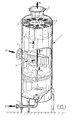
- FIG. 1 shows an upright separating vessel 1 for separating a pressurized flow of a gas/liquid mixture, such as natural gas mixed with (salt sea-)water, into a substantially gas-containing fraction, also referred to as light fraction, and a substantially liquid-containing (water and/or oil) fraction, also referred to as heavy fraction.
- Vessel 1 is provided with a connecting stub 2 for in feed of the gas/liquid mixture, a connecting stub for a liquid discharge conduit 4 for discharge of the heavy fraction and a connecting stub 5 for discharge of the light fraction.
- the gas/liquid flow introduced in the vessel 1 (P 1 ) is guided by a pre-treatment unit 3 to a lower compartment A of vessel 1.
- the pre-treatment unit 3 is formed by a number of curved blades or vanes which uniformly absorb the moment of the incoming gas/liquid flow.
- the vanes subsequently guide the gas/liquid flow laterally (P 2 ) into the lower compartment of the separating vessel.
- a first part of the liquid (F) will already be separated and accumulate at the bottom of the vessel 1 (P 3 ).
- the cyclones are arranged in a plurality of boxes in the upper compartment B of the vessel 1.
- the connecting stub 5 Provided downstream thereof is the connecting stub 5 for discharging the light fraction (mainly gas) which has been dried to a considerable extent.
- the cyclones are connected to one or more downcomers 7 which are in communication with liquid F at the bottom of the vessel for draining liquid from each of the cyclones.
- the cyclones are axial recycle cyclones as disclosed in the aforementioned document WO 00/25931 .
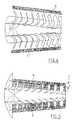
- Figure 2 shows a vane type inlet device 10, which comprises a bottom plate 11 and a top plate 12. Between the plates a number of partly straight partly curved guiding vanes 9 are arranged. The guiding vanes are designed so as to guide the incoming flow sideways.
- a liquid/gas flow entering the inlet device (P 7 ) is intercepted by the leading edge 21 of a guiding vane 9 and deflected laterally (P 8 ). Downstream of the trailing end 20 of the guiding vanes 9 a wire mesh 13 is arranged downstream of the trailing end 20 of the guiding vanes 9 .
- the wire mesh 13 can be attached to the inlet device 10 itself, for example to its support plates 11 and 12, or may be connected to a separate frame, that is attached directly to the separation vessel 1 itself.
- the wire mesh pad is a layer of tightly packed wires, the layer being arranged vertically, downstream of the guiding vanes.
- FIG 3 shows another embodiment of the present invention.
- a vane type inlet device of a different design also known as the "Evenflow” inlet device
- the Evenflow inlet device differs from the device shown in figure 2 in a number of aspects, the most important ones being that the guiding vanes are curved over their total length, the guiding vanes are maintained between the borders of the upper and lower plates 11,12 and that the interspace between the successive guiding vanes increases in the direction of the mixture flow (P 8 ).
- the basic principle of intercepting the mixture flow and deflecting the flow towards the wall of the vessel is however the same.
- a number of mesh pads 14 is arranged between the guiding vanes 9'.
- the mesh pads 14, as shown in figure 3 are arranged close to the trailing end of the vanes. They may, however, also be arranged close to the leading edge of the vanes or along the entire area of the vanes.
- FIG. 5 shows another preferred embodiment of an inlet vane type device according to the design of the Evenflow inlet device.
- the mesh pad 15 is not only arranged between the guiding vanes 9', but also downstream of the guiding vanes. In fact the mesh pad 15 protrudes over a distance (a) of 0-500 millimetre from the trailing edges of the respective guiding vanes.
- Figure 6 shows another preferred embodiment of the separator according to the invention.
- the figure shows a separating vessel 1 provided with a vane-type inlet device 3 as discussed above.
- Shown is a wire mesh 30 that is situated on a position between the inlet 2 of the separator 1 and the surface of the liquid f accumulated at the bottom of the vessel.
- Shown is a particular embodiment wherein the wire mesh is divided in two mesh parts 30,30', being arranged adjacent to the wall 31 of the vessel. Between the mesh parts 30,30' an opening is left. The incoming mixture will be deflected sideways and be forced through the two wire mesh parts 30, 30'. Both wire mesh parts will retain some of the liquid contained in the gas, which liquid will drop down into the fluid F already present there. The remaining part of the mixture will be forced upward, mainly through said opening between both wire mesh parts 30,30'.
- the opening is provided in order to improve the upward flow of the mixture (mainly containing gas).
- the opening has an elongated shape, but can be shaped differently depending on the specific type of separation used, the characteristics of the incoming mixture, et cetera. In particular cases wherein there are large skew distributions and the inlet devices are heavily loaded (i.e. high gas loads), the mesh pad must be made larger and hence the opening is chosen to be smaller.
- the wire mesh can alternatively be formed so as to cover the entire cross section of the vessel 1. In many circumstances this embodiment is preferred since it will provide a very uniform distribution of the mixture.
- FIG. 7 shows a further preferred embodiment of the invention wherein the inlet device, e.g. a vane type inlet device, is schematically shown and the wire mesh is arranged vertically in the vessel 1.
- the wire mesh is in this embodiment attached to a support structure 31, comprising a solid plate or, preferably, a further wire mesh, perforated plate or a structured/random packing.
- the mixture flowing sideways out of the inlet device 3 will be more uniformly distributed in the vessel by the shown arrangement of the wire mesh 32.
- Figure 8 shows the embodiment of figure 3 , wherein the mesh 33 is arranged at an angle ⁇ (10° ⁇ ⁇ ⁇ 170°) to the vessel wall, extending upwards or downwards.
- the mesh 33 is attached directly to the vessel wall 38.
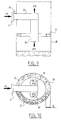
- FIGS 9 and 10 show cross-sections of an embodiment not according to the present invention.
- a cyclone type inlet device 34 is employed.
- the inlet device 34 comprises a horizontal tube 35 which is connected to two cyclones 36,36'.
- Each cyclone comprises a tangential inlet, forcing the mixture coming from the tube 35 to rotate (P 10 ).
- P 11 Under the influence of the rotating movement of the mixture inside the cyclones 36, 36' a heavy fraction of the mixture is discharged downward (P 11 ), while a light fraction of the mixture is discharged upward (P 12 ).
- a cyclone type inlet device referral is made to the international publication WO 00/74815 A2 of the present applicant.
- Figures 9 and 10 show that the mesh pad in this embodiment is arranged along the whole perimeter of the vessel wall 38.
- the width W of the wire mesh 37 will depend from case to case. Instead of being only a strip along the vessel wall, as is shown in figure 10 , the wire mesh may cover the whole area (excluding the area occupied by the inlet cyclones 36,36' themselves) or only different strips on parts of the vessel wall 38.
- the dimensions and shape of the opening between the two wire mesh pads will in practice depend on the specific separating requirements and/or the quality of the incoming mixture.
- Other configurations or layouts of mesh pads inside the separation vessel may also be advantageous.
Landscapes
- Chemical & Material Sciences (AREA)
- Chemical Kinetics & Catalysis (AREA)
- Cyclones (AREA)
Applications Claiming Priority (2)
| Application Number | Priority Date | Filing Date | Title |
|---|---|---|---|
| NL1024149A NL1024149C2 (nl) | 2003-08-22 | 2003-08-22 | Inlaat- en verdeelinrichting. |
| PCT/EP2004/009365 WO2005018780A2 (en) | 2003-08-22 | 2004-08-20 | Separation device an inlet therefor |
Publications (2)
| Publication Number | Publication Date |
|---|---|
| EP1663448A2 EP1663448A2 (en) | 2006-06-07 |
| EP1663448B1 true EP1663448B1 (en) | 2011-12-07 |
Family
ID=34214848
Family Applications (1)
| Application Number | Title | Priority Date | Filing Date |
|---|---|---|---|
| EP04764347A Expired - Lifetime EP1663448B1 (en) | 2003-08-22 | 2004-08-20 | Inlet and distribution device |
Country Status (6)
| Country | Link |
|---|---|
| US (1) | US7488361B2 (nl) |
| EP (1) | EP1663448B1 (nl) |
| AT (1) | ATE536215T1 (nl) |
| AU (1) | AU2004266073B2 (nl) |
| NL (1) | NL1024149C2 (nl) |
| WO (1) | WO2005018780A2 (nl) |
Families Citing this family (43)
| Publication number | Priority date | Publication date | Assignee | Title |
|---|---|---|---|---|
| NL1024149C2 (nl) * | 2003-08-22 | 2005-02-23 | Flash Technologies N V | Inlaat- en verdeelinrichting. |
| JP2008540111A (ja) | 2005-05-19 | 2008-11-20 | シエル・インターナシヨナル・リサーチ・マートスハツペイ・ベー・ヴエー | 流体取入装置、使用およびリトロフィット方法 |
| NL1029230C2 (nl) * | 2005-06-10 | 2006-12-12 | Fmc Technologies Cv | Systeem en inlaatinrichting voor het scheiden van een mengsel. |
| FR2888133B1 (fr) * | 2005-10-11 | 2007-10-19 | Air Liquide | Diffuseur de gaz et colonne incorporant un tel diffuseur |
| US20080257147A1 (en) * | 2005-12-06 | 2008-10-23 | Johnson Matthey Plc | Gas Distributor |
| CA2633412C (en) | 2005-12-20 | 2016-05-24 | Shell Internationale Research Maatschappij B.V. | Fluid inlet device, use, and method of retrofitting |
| US7513271B2 (en) * | 2006-05-12 | 2009-04-07 | Sulzer Chemtech Ag | Fluid inlet device for an apparatus |
| NO326078B1 (no) * | 2006-07-07 | 2008-09-15 | Shell Int Research | Fluidseparasjonskar |
| CN101541394A (zh) * | 2006-11-30 | 2009-09-23 | 西湖朗维尤公司 | 高压分离器 |
| US7867310B2 (en) * | 2009-01-29 | 2011-01-11 | General Electric Company | Method and apparatus for separating air and oil |
| US8147575B2 (en) * | 2009-09-09 | 2012-04-03 | Ingersoll-Rand Company | Multi-stage oil separation system including a cyclonic separation stage |
| WO2011031154A2 (en) * | 2009-09-11 | 2011-03-17 | Advanced Tail-End Oil Company N.V. | Pre-separating vane diffuser and method for introducing a flow-mixture in a separator |
| US8627848B2 (en) | 2010-10-01 | 2014-01-14 | The Chem-Pro Group Llc | Vane inlet device |
| NO333860B1 (no) | 2010-10-08 | 2013-10-07 | Cameron Systems As | Innløpsanordning for gravitasjonsseparator |
| RU2460023C1 (ru) * | 2011-03-22 | 2012-08-27 | Закрытое акционерное общество Финансовая компания "Центр Космос-Нефть-Газ" | Монтажно-транспортный комплекс газосепаратора промежуточного |
| CN102179113B (zh) * | 2011-04-18 | 2013-01-23 | 上海南悦机电科技有限公司 | 一种抽气机的气液分离罐及气液分离方法 |
| US8500837B2 (en) * | 2011-06-29 | 2013-08-06 | Peerless Mfg. Co. | Enhanced vane bundle design |
| US10792604B2 (en) * | 2015-06-25 | 2020-10-06 | Tm Industrial Supply, Inc. | Horizontal coalescing filter |
| CA2929414C (en) | 2015-06-29 | 2023-08-22 | SegreTECH Inc. | Method and apparatus for removal of sand from gas |
| US20170087497A1 (en) * | 2015-09-29 | 2017-03-30 | Chevron U.S.A. Inc. | Inlet distributor device and methods for use and design thereof |
| KR101779538B1 (ko) | 2015-10-27 | 2017-09-18 | 지에스건설 주식회사 | 베셀의 인렛 디바이스 |
| PL3407998T3 (pl) * | 2016-01-27 | 2021-12-13 | Koch-Glitsch, Lp | Wlotowe urządzenie łopatkowe z wewnętrzną belką w celu uzyskania usztywnienia i zbiornik zawierający takie urządzenie |
| SI3244152T1 (sl) * | 2016-05-12 | 2020-02-28 | Danieli Corus Bv | Postroj peči in postopek za obdelavo dimnega plina |
| CN106040452A (zh) * | 2016-06-29 | 2016-10-26 | 安德油气工艺技术(天津)有限公司 | 旋流分离器 |
| CN106215603A (zh) * | 2016-09-22 | 2016-12-14 | 淮南矿业(集团)有限责任公司 | 煤矿抽采气体去杂质装置 |
| BE1024631B9 (nl) * | 2016-10-11 | 2019-05-13 | Atlas Copco Airpower Nv | Vloeistofafscheider |
| US9643105B1 (en) * | 2016-12-01 | 2017-05-09 | Worthington Industries, Inc. | Inlet diverter |
| CN107061985A (zh) * | 2017-05-23 | 2017-08-18 | 河南美丽乡村环保科技有限公司 | 气液分离低压储气装置 |
| US10933351B2 (en) * | 2018-04-30 | 2021-03-02 | Bendix Commercial Vehicle Systems Llc | Effluent processing apparatus for a vehicle air brake charging system |
| CA3081098C (en) * | 2018-08-29 | 2021-04-13 | Bechtel Oil, Gas And Chemicals, Inc. | Flow-diverger feed inlet distributor |
| US11065559B2 (en) | 2018-12-21 | 2021-07-20 | EnXL LLC | Cyclonic inlet diverter |
| US11274540B2 (en) | 2019-04-29 | 2022-03-15 | Westerman, Inc. | Heated separation assembly |
| US11274539B2 (en) | 2019-04-29 | 2022-03-15 | Westerman, Inc. | Heated separation assembly |
| RU2716769C1 (ru) * | 2019-05-06 | 2020-03-16 | Руслан Ильдарович Салимгареев | Газораспределительное устройство |
| US11285405B2 (en) | 2019-10-08 | 2022-03-29 | EnXL LLC | Inclined linear multi-phase gravity separation system |
| CN110787597B (zh) * | 2019-12-05 | 2024-06-18 | 中国石油大学(北京) | 气液分离设备 |
| DE102020001716A1 (de) * | 2020-03-11 | 2021-09-16 | Walter Kramer | Abscheider zur Trennung eines Fördermediums, vorzugsweise Luft, von einem Fördergut und Verfahren zum Abscheiden von Fördergut aus einem Fördermedium-Fördergut-Gemisch |
| CN214039059U (zh) * | 2020-08-18 | 2021-08-24 | 青岛海尔特种电冰箱有限公司 | 用于制冷系统的储液器及冰箱 |
| CN113648775A (zh) * | 2021-09-17 | 2021-11-16 | 华东理工大学 | 气体降温-洗涤装置与方法 |
| US12352390B1 (en) * | 2022-02-17 | 2025-07-08 | Blue Origin Manufacturing, LLC | Diffuser for recirculated liquids |
| US12082373B2 (en) * | 2022-03-21 | 2024-09-03 | Baidu Usa Llc | Two-phase system in server cluster |
| US12017159B2 (en) * | 2022-09-16 | 2024-06-25 | Syncrude Canada Ltd. | Feedwell for an inclined plate separator |
| US20240226782A9 (en) * | 2022-10-21 | 2024-07-11 | Blue Skies Global LLC | Regenerative media filter |
Family Cites Families (15)
| Publication number | Priority date | Publication date | Assignee | Title |
|---|---|---|---|---|
| US1739093A (en) * | 1926-06-17 | 1929-12-10 | Continental Oil Co | Gas separator |
| US3063220A (en) * | 1957-06-10 | 1962-11-13 | Wallace E Almquist | Vapor-liquid contactor and separator |
| US3010537A (en) * | 1959-12-14 | 1961-11-28 | Socony Mobil Oil Co | Mist extractor |
| US3997303A (en) * | 1975-05-01 | 1976-12-14 | Air Products And Chemicals, Inc. | Liquid-gas phase separator having a perforated plate and mist eliminator pad |
| US4297116A (en) * | 1978-07-10 | 1981-10-27 | Aitken, Inc. | Apparatus for separating foreign matter from a gas stream |
| US4296116A (en) | 1978-11-16 | 1981-10-20 | Bayer Aktiengesellschaft | Fungicidal agents, processes for their preparation and their use for combating fungi |
| DE3662839D1 (en) * | 1985-03-05 | 1989-05-24 | Shell Int Research | Column for removing liquid from a gas |
| US5676717A (en) * | 1995-11-13 | 1997-10-14 | Ingersoll-Rand Company | Separator tank |
| NL1010478C2 (nl) | 1998-11-04 | 2000-05-08 | Cds Engineering B V | Inrichting voor het behandelen van een gas/vloeistofmengsel. |
| US6251168B1 (en) * | 1999-07-23 | 2001-06-26 | Hudson Products Corporation | High efficiency gas scrubber using combined coalescing media and centrifugal cyclone |
| NO315788B1 (no) * | 2001-10-18 | 2003-10-27 | Consept As | Vertikalt orientert separator for fjerning av v¶skedråper fra en gasström |
| NO315188B1 (no) * | 2001-11-07 | 2003-07-28 | Consept As | Dråpefangersyklon |
| NL1020113C2 (nl) * | 2002-03-05 | 2003-09-10 | Statoil Asa | Inrichting en werkwijze voor het behandelen van een gas/vloeistofmengsel. |
| NL1024149C2 (nl) * | 2003-08-22 | 2005-02-23 | Flash Technologies N V | Inlaat- en verdeelinrichting. |
| DE602004012420T2 (de) * | 2003-09-09 | 2008-06-19 | Shell Internationale Research Maatschappij B.V. | Gas/flüssigkeits-abscheider |
-
2003
- 2003-08-22 NL NL1024149A patent/NL1024149C2/nl not_active IP Right Cessation
-
2004
- 2004-08-20 AT AT04764347T patent/ATE536215T1/de active
- 2004-08-20 WO PCT/EP2004/009365 patent/WO2005018780A2/en not_active Ceased
- 2004-08-20 AU AU2004266073A patent/AU2004266073B2/en not_active Ceased
- 2004-08-20 US US10/569,091 patent/US7488361B2/en not_active Expired - Fee Related
- 2004-08-20 EP EP04764347A patent/EP1663448B1/en not_active Expired - Lifetime
Also Published As
| Publication number | Publication date |
|---|---|
| AU2004266073B2 (en) | 2009-12-03 |
| US7488361B2 (en) | 2009-02-10 |
| NL1024149C2 (nl) | 2005-02-23 |
| WO2005018780A2 (en) | 2005-03-03 |
| EP1663448A2 (en) | 2006-06-07 |
| WO2005018780A3 (en) | 2007-02-01 |
| AU2004266073A1 (en) | 2005-03-03 |
| US20070044437A1 (en) | 2007-03-01 |
| ATE536215T1 (de) | 2011-12-15 |
Similar Documents
| Publication | Publication Date | Title |
|---|---|---|
| EP1663448B1 (en) | Inlet and distribution device | |
| AU2006255877B2 (en) | System and inlet device for separating a mixture | |
| EP1660212B1 (en) | Gas/liquid separator | |
| JP4509388B2 (ja) | 三相分離器 | |
| US9039799B2 (en) | Drained coalescer | |
| US7488373B2 (en) | Device and method for treating a gas/liquid mixture | |
| CA2772828A1 (en) | Pre-separating vane diffuser and method for introducing a flow-mixture in a separator | |
| US8025718B2 (en) | Fluid inlet device, use, and method of retrofitting | |
| JP2009519823A (ja) | 流体入口装置、使用法、およびリトロフィットの方法 | |
| RU2666414C1 (ru) | Сепаратор центробежный газожидкостный югаз.цгс | |
| NL1025086C2 (nl) | Inlaat- en verdelingsinrichting. |
Legal Events
| Date | Code | Title | Description |
|---|---|---|---|
| PUAI | Public reference made under article 153(3) epc to a published international application that has entered the european phase |
Free format text: ORIGINAL CODE: 0009012 |
|
| 17P | Request for examination filed |
Effective date: 20060217 |
|
| AK | Designated contracting states |
Kind code of ref document: A2 Designated state(s): AT BE BG CH CY CZ DE DK EE ES FI FR GB GR HU IE IT LI LU MC NL PL PT RO SE SI SK TR |
|
| AX | Request for extension of the european patent |
Extension state: AL HR LT LV MK |
|
| DAX | Request for extension of the european patent (deleted) | ||
| PUAK | Availability of information related to the publication of the international search report |
Free format text: ORIGINAL CODE: 0009015 |
|
| 17Q | First examination report despatched |
Effective date: 20070810 |
|
| RAP1 | Party data changed (applicant data changed or rights of an application transferred) |
Owner name: FMC TECHNOLOGIES C.V. |
|
| GRAP | Despatch of communication of intention to grant a patent |
Free format text: ORIGINAL CODE: EPIDOSNIGR1 |
|
| GRAS | Grant fee paid |
Free format text: ORIGINAL CODE: EPIDOSNIGR3 |
|
| GRAA | (expected) grant |
Free format text: ORIGINAL CODE: 0009210 |
|
| AK | Designated contracting states |
Kind code of ref document: B1 Designated state(s): AT BE BG CH CY CZ DE DK EE ES FI FR GB GR HU IE IT LI LU MC NL PL PT RO SE SI SK TR |
|
| REG | Reference to a national code |
Ref country code: GB Ref legal event code: FG4D |
|
| REG | Reference to a national code |
Ref country code: CH Ref legal event code: EP |
|
| REG | Reference to a national code |
Ref country code: IE Ref legal event code: FG4D |
|
| REG | Reference to a national code |
Ref country code: DE Ref legal event code: R096 Ref document number: 602004035601 Country of ref document: DE Effective date: 20120209 |
|
| REG | Reference to a national code |
Ref country code: NL Ref legal event code: VDEP Effective date: 20111207 |
|
| PG25 | Lapsed in a contracting state [announced via postgrant information from national office to epo] |
Ref country code: SE Free format text: LAPSE BECAUSE OF FAILURE TO SUBMIT A TRANSLATION OF THE DESCRIPTION OR TO PAY THE FEE WITHIN THE PRESCRIBED TIME-LIMIT Effective date: 20111207 Ref country code: GR Free format text: LAPSE BECAUSE OF FAILURE TO SUBMIT A TRANSLATION OF THE DESCRIPTION OR TO PAY THE FEE WITHIN THE PRESCRIBED TIME-LIMIT Effective date: 20120308 Ref country code: NL Free format text: LAPSE BECAUSE OF FAILURE TO SUBMIT A TRANSLATION OF THE DESCRIPTION OR TO PAY THE FEE WITHIN THE PRESCRIBED TIME-LIMIT Effective date: 20111207 Ref country code: SI Free format text: LAPSE BECAUSE OF FAILURE TO SUBMIT A TRANSLATION OF THE DESCRIPTION OR TO PAY THE FEE WITHIN THE PRESCRIBED TIME-LIMIT Effective date: 20111207 |
|
| PG25 | Lapsed in a contracting state [announced via postgrant information from national office to epo] |
Ref country code: BE Free format text: LAPSE BECAUSE OF FAILURE TO SUBMIT A TRANSLATION OF THE DESCRIPTION OR TO PAY THE FEE WITHIN THE PRESCRIBED TIME-LIMIT Effective date: 20111207 Ref country code: CY Free format text: LAPSE BECAUSE OF FAILURE TO SUBMIT A TRANSLATION OF THE DESCRIPTION OR TO PAY THE FEE WITHIN THE PRESCRIBED TIME-LIMIT Effective date: 20111207 |
|
| PG25 | Lapsed in a contracting state [announced via postgrant information from national office to epo] |
Ref country code: SK Free format text: LAPSE BECAUSE OF FAILURE TO SUBMIT A TRANSLATION OF THE DESCRIPTION OR TO PAY THE FEE WITHIN THE PRESCRIBED TIME-LIMIT Effective date: 20111207 Ref country code: EE Free format text: LAPSE BECAUSE OF FAILURE TO SUBMIT A TRANSLATION OF THE DESCRIPTION OR TO PAY THE FEE WITHIN THE PRESCRIBED TIME-LIMIT Effective date: 20111207 Ref country code: BG Free format text: LAPSE BECAUSE OF FAILURE TO SUBMIT A TRANSLATION OF THE DESCRIPTION OR TO PAY THE FEE WITHIN THE PRESCRIBED TIME-LIMIT Effective date: 20120307 Ref country code: CZ Free format text: LAPSE BECAUSE OF FAILURE TO SUBMIT A TRANSLATION OF THE DESCRIPTION OR TO PAY THE FEE WITHIN THE PRESCRIBED TIME-LIMIT Effective date: 20111207 |
|
| PG25 | Lapsed in a contracting state [announced via postgrant information from national office to epo] |
Ref country code: PL Free format text: LAPSE BECAUSE OF FAILURE TO SUBMIT A TRANSLATION OF THE DESCRIPTION OR TO PAY THE FEE WITHIN THE PRESCRIBED TIME-LIMIT Effective date: 20111207 Ref country code: PT Free format text: LAPSE BECAUSE OF FAILURE TO SUBMIT A TRANSLATION OF THE DESCRIPTION OR TO PAY THE FEE WITHIN THE PRESCRIBED TIME-LIMIT Effective date: 20120409 Ref country code: RO Free format text: LAPSE BECAUSE OF FAILURE TO SUBMIT A TRANSLATION OF THE DESCRIPTION OR TO PAY THE FEE WITHIN THE PRESCRIBED TIME-LIMIT Effective date: 20111207 |
|
| REG | Reference to a national code |
Ref country code: AT Ref legal event code: MK05 Ref document number: 536215 Country of ref document: AT Kind code of ref document: T Effective date: 20111207 |
|
| PLBE | No opposition filed within time limit |
Free format text: ORIGINAL CODE: 0009261 |
|
| STAA | Information on the status of an ep patent application or granted ep patent |
Free format text: STATUS: NO OPPOSITION FILED WITHIN TIME LIMIT |
|
| PG25 | Lapsed in a contracting state [announced via postgrant information from national office to epo] |
Ref country code: DK Free format text: LAPSE BECAUSE OF FAILURE TO SUBMIT A TRANSLATION OF THE DESCRIPTION OR TO PAY THE FEE WITHIN THE PRESCRIBED TIME-LIMIT Effective date: 20111207 |
|
| 26N | No opposition filed |
Effective date: 20120910 |
|
| PG25 | Lapsed in a contracting state [announced via postgrant information from national office to epo] |
Ref country code: IT Free format text: LAPSE BECAUSE OF FAILURE TO SUBMIT A TRANSLATION OF THE DESCRIPTION OR TO PAY THE FEE WITHIN THE PRESCRIBED TIME-LIMIT Effective date: 20111207 |
|
| REG | Reference to a national code |
Ref country code: DE Ref legal event code: R097 Ref document number: 602004035601 Country of ref document: DE Effective date: 20120910 |
|
| PG25 | Lapsed in a contracting state [announced via postgrant information from national office to epo] |
Ref country code: AT Free format text: LAPSE BECAUSE OF FAILURE TO SUBMIT A TRANSLATION OF THE DESCRIPTION OR TO PAY THE FEE WITHIN THE PRESCRIBED TIME-LIMIT Effective date: 20111207 |
|
| REG | Reference to a national code |
Ref country code: CH Ref legal event code: PL |
|
| PG25 | Lapsed in a contracting state [announced via postgrant information from national office to epo] |
Ref country code: MC Free format text: LAPSE BECAUSE OF NON-PAYMENT OF DUE FEES Effective date: 20120831 |
|
| PG25 | Lapsed in a contracting state [announced via postgrant information from national office to epo] |
Ref country code: ES Free format text: LAPSE BECAUSE OF FAILURE TO SUBMIT A TRANSLATION OF THE DESCRIPTION OR TO PAY THE FEE WITHIN THE PRESCRIBED TIME-LIMIT Effective date: 20120318 Ref country code: CH Free format text: LAPSE BECAUSE OF NON-PAYMENT OF DUE FEES Effective date: 20120831 Ref country code: LI Free format text: LAPSE BECAUSE OF NON-PAYMENT OF DUE FEES Effective date: 20120831 |
|
| REG | Reference to a national code |
Ref country code: IE Ref legal event code: MM4A |
|
| PG25 | Lapsed in a contracting state [announced via postgrant information from national office to epo] |
Ref country code: FI Free format text: LAPSE BECAUSE OF FAILURE TO SUBMIT A TRANSLATION OF THE DESCRIPTION OR TO PAY THE FEE WITHIN THE PRESCRIBED TIME-LIMIT Effective date: 20111207 |
|
| PG25 | Lapsed in a contracting state [announced via postgrant information from national office to epo] |
Ref country code: IE Free format text: LAPSE BECAUSE OF NON-PAYMENT OF DUE FEES Effective date: 20120820 |
|
| PG25 | Lapsed in a contracting state [announced via postgrant information from national office to epo] |
Ref country code: TR Free format text: LAPSE BECAUSE OF FAILURE TO SUBMIT A TRANSLATION OF THE DESCRIPTION OR TO PAY THE FEE WITHIN THE PRESCRIBED TIME-LIMIT Effective date: 20111207 |
|
| PG25 | Lapsed in a contracting state [announced via postgrant information from national office to epo] |
Ref country code: LU Free format text: LAPSE BECAUSE OF NON-PAYMENT OF DUE FEES Effective date: 20120820 |
|
| PG25 | Lapsed in a contracting state [announced via postgrant information from national office to epo] |
Ref country code: HU Free format text: LAPSE BECAUSE OF FAILURE TO SUBMIT A TRANSLATION OF THE DESCRIPTION OR TO PAY THE FEE WITHIN THE PRESCRIBED TIME-LIMIT Effective date: 20040820 |
|
| PGFP | Annual fee paid to national office [announced via postgrant information from national office to epo] |
Ref country code: DE Payment date: 20140813 Year of fee payment: 11 |
|
| PGFP | Annual fee paid to national office [announced via postgrant information from national office to epo] |
Ref country code: GB Payment date: 20140820 Year of fee payment: 11 Ref country code: FR Payment date: 20140808 Year of fee payment: 11 |
|
| REG | Reference to a national code |
Ref country code: DE Ref legal event code: R119 Ref document number: 602004035601 Country of ref document: DE |
|
| GBPC | Gb: european patent ceased through non-payment of renewal fee |
Effective date: 20150820 |
|
| REG | Reference to a national code |
Ref country code: FR Ref legal event code: ST Effective date: 20160429 |
|
| PG25 | Lapsed in a contracting state [announced via postgrant information from national office to epo] |
Ref country code: DE Free format text: LAPSE BECAUSE OF NON-PAYMENT OF DUE FEES Effective date: 20160301 Ref country code: GB Free format text: LAPSE BECAUSE OF NON-PAYMENT OF DUE FEES Effective date: 20150820 |
|
| PG25 | Lapsed in a contracting state [announced via postgrant information from national office to epo] |
Ref country code: FR Free format text: LAPSE BECAUSE OF NON-PAYMENT OF DUE FEES Effective date: 20150831 |